2. Shougang Jingtang Iron and Steel United Co., Ltd., Tangshan 063200, Hebei, China
Application of the double cold reduction (DCR) in the can industry has developed significantly because of its higher strength and thinner enhancing utilization efficiency and reduced cost in light-weight[1]. The strip thickness after annealing is reduced at the first skin pass mill (SPM) stand and the second mill stand applies a temper pass to achieve the final strip thickness. These steels own excellent deep formability and high hardness, that is better for the process of can manufacturing[2]. A better formability can be achieved through types of fibers control[3]. It is considered that {111} fiber is good for the formability, while {001} is not thirsted. Furthermore, {111} fiber, which exhibited intensities of {111} <110> and {111} <112> components, leads to a relative low ears[4]. However, when the right hardness of double cold reduction tinplate are obtained, the non-earing property is difficult to be obtained. So, the control of fiber types and earing property demands to be enhanced.
The TSLOM software was used to measure the orientation distribution functions and U2= 45° sections were determined[5]. There are two different routes before the second reduction through SPM with two stands. The study on double cold reduction-drawn and redrawn (DRD) tinplate steel is markedly overdue. The deep drawing and earing properties were applied to aluminum killed steels that differed from other research on the interstitial-free steel to produce thin tinplate for sophisticated packaging applications. The present researches pay close attention only to the texture of IF steels, while the IF steels are not used widely. So the relation among different processes, textures, reduction and earing properties have not been systematically researched. In our experiment the relationships are well researched to offer guidance for the development and research of the double reduced tinplate steels. The double reduced tinplate steels contain four varied grade according to different hardness such as DR7M, DR8, DR9 and DR10.
2 Materials and MethodsThe two steels for this study were industrially prepared and their chemical compositions are provided in Table 1. The material used for the present study was aluminum killed steel. Steel 1 was processed through the CA route while Steel 2 was processed through the BA route.
| Table 1 Chemical composition |
The processing parameters for the two steels are given in Table 2. The hot-rolled sheets were then cold-rolled to 0.2 mm thicknesses, after which they were annealed through continuous annealing or batch annealing, and then double cold-rolled to 0.16 or 0.15 mm in order to get the right hardness.
| Table 2 Processing parameters for the two steels |
The sheet forming machine was used for the earing test. Earing peak height ht, earing valley height hv, earing height he, maximum earing height hmax and earing ratio Ze are defined by Eqs.(1)-(5):
| $ \overline{h_{t}}=\frac{h_{t 1}+h_{t 2}+h_{t 3}+\cdots \cdots}{\text { Amountofearingpeak }} $ | (1) |
| $ \overline{h_{v}}=\frac{h_{t 1}+h_{t 2}+h_{t 3}+\cdots \cdots}{\text { Amountofearingvalley }} $ | (2) |
| $ \overline{h_{e}}=\overline{h_{t}}-\overline{h_{v}} $ | (3) |
| $ h_{\max }=h_{t\operatorname{max}}-h_{v \max } $ | (4) |
| $ Z_{e}=\frac{\overline{h_{e}}}{\overline{h_{v}}} \times 100 \% $ | (5) |
Microstructures and precipitates were studied with a SEM. The Image Tool software was used to measure the grain size. The types of fibers were measured through X-ray diffraction (XRD). X-ray photo electron spectroscopy (XPS) is a surface analysis technique used to measure the composition of carbon in the different steels[6-8].
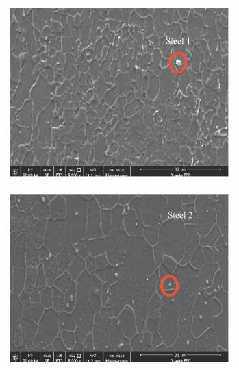
3 Experimental Results 3.1 Microstructure AnalysisThe microstructures of the two steels revealed the presence of well recrystallized grains. The main microstructures are ferrite with small quantities of carbide. Black grains are identified as ferrite and white particles as carbide, as shown in Fig. 1. The carbides show a general alignment with the rolling direction at grain boundaries of ferrite grains in Steel 1. However, elongated ferrite grain structures and zonal distributed carbides in Steel 2 are less obvious. The Heyn Intercept Method was applied to measure the average grain size of ferrite as a function of time on longitudinal (d(l)), transverse (d(t)) and normal surface (d(n))[9]. An average global grain size Daverage, was calculated using Eq.(6).
|
Fig.1 SEM micrographs of two DR8 tinplate samples after final rolling |
| $ D_{\text { average }}=\frac{1}{3}\left(d_{(l)}+d_{(t)}+d_{(n)}\right) $ | (6) |
Using tango-maps software, the grain size of the steels were estimated to be 7.04 μm and 10.12 μm when the routes of annealing were continuous annealing and batch annealing, respectively. This would be attributable longer annealing time in the case of Steel 2 as compared with Steel 1.
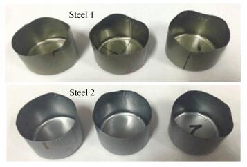
3.2 Mechanical PropertyThe drawn cups for determining earing height are shown in Fig. 2 and the results are listed in Table 3. It can be seen that Steel 1 displays higher Ze, he and hmax than that of Steel 2.
|
Fig.2 Drawn cups of a sample for determining the earing height |
| Table 3 The earing property of the steels |
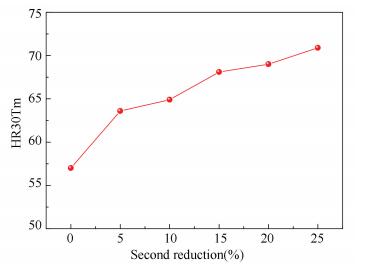
Before the second rolling process, the hardness after batch annealing is lower than that of continuous annealing both being lower than what is requirement for the double reduced (DR) steels standard, in order to get the proper hardness, more reduction is needed. The relation between hardness and reduction is shown in Fig. 3.
|
Fig.3 Hardness at different second reduction |
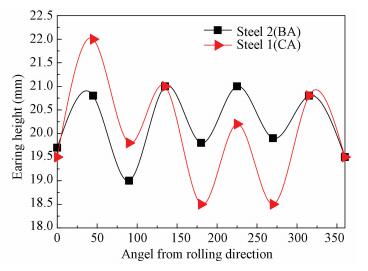
Moreover, the earing positions of two steels are all at a 45° direction. The earing heights at varied angels from rolling direction are exhibited in Fig. 4. It can be concluded that the decrease of non-{111} texture and the increase of {111} fiber texture are in favor of the decrease of earing ratio, accompanied with the change of earing position from 45° to 0°/60°, as described by Li et al.[10].
|
Fig.4 The cup height at different angel from rolling direction |
4 Analysis and Discussion
It is widely accepted that a strong and homogeneous {111} fiber texture is favorable to obtain a non-earing property. The effects of {111} <110> and {111} <112> cancel out one another and lead to a nearly earing free condition[2].
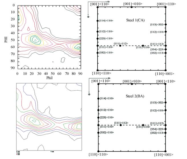
Fig. 5 reveals the ϕ2 = 45° section of the ODF derived from XRD for the two DR tinplate steel sheets. As observed from the ODFs, the textures of the two steels consist of fibers. Steel 2 exhibits high intensities around the {111} <112>, {112} <110>and {223} <110> texture. Steel 1 also shows high intensities around {001} <110> and {114} <110>. The orientation intensities along α and γ fiber of the steels is exhibited in Fig. 6.
|
Fig.5 ODF (φ2 = 45° section) of the two steels after final rolling |

|
Fig.6 Orientation intensities along α (φ1 = 0°, φ2 = 45°) and γ (ϕ= 55°, φ2 = 45°) fibre of the two steels |
According to the figure, the intensity of γ fiber in Steel 2 is generally much higher than that of the γ fiber in Steel 1, that is attributed to the higher reduction as Kaneharu OKuDA has mentioned[11]. Steel 2 displays higher intensity around {112} <110> and {223} <110>components and both the intensities of {001} <110> and {114} <110> texture components are lower than that of Steel 1. In addition Goss orientation {110} <110> in Steel 2 does not vanish completely and the volume fraction of the orientation is 0.25% which is lower than that of Steel 1. This orientation may reduce the draw ability.
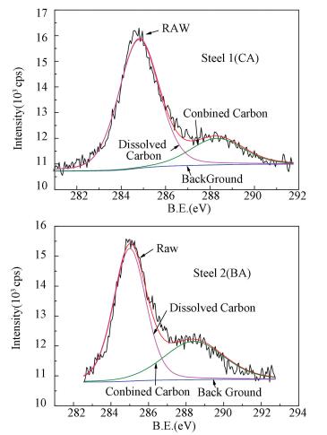
The steels contains aluminum to stabilize the nitrogen by forming aluminum nitrides. Only considering the solute carbon, Fig. 7 illustrates C1s XPS spectra and corresponding fitting curves of the two DR tinplate samples. Two peaks at 284.8 and 288.2 eV correspond with the C1s peak of dissolved carbon and carbide respectively on the basis of the NIST database. To clarify, the peak at 284.8 eV also contains the system carbon that cannot be eliminated during testing. However, the intensities of system carbon are the same in two XPS spectra because the samples were tested under the same conditions in one batch, therefore the contrasting relationship of dissolved carbon within the two samples is still the same. By means of definite integral, the peak areas were worked out[12], and they are listed in Table 4. It can be concluded that Steel 1 has higher dissolved carbon content, while its carbide content is less.
|
Fig.7 XPS spectra and fitting curve of C1s |
| Table 4 Peak area of each peak of three DR-8D tinplate samples |
This agrees with the diffusion equation written as Eq.(7). Because the annealing time of Steels 2 is, much longer than that of Steel 1. There is more solute carbon diffused in relation to grain boundaries[13]. It is agreed that dissolved carbon contents are associated with modest refinement of the grain structure.
| $ \frac{\partial c}{\partial t}=D\left(\frac{2}{r} \frac{\partial c}{\partial r}+\frac{\partial^{2} c}{\partial r^{2}}\right) $ | (7) |
where D=D0exp(-Ud/RT) equals the diffusion coefficient (m2/s); r is the radial distance, which equals the grain size, and c denotes carbon atom-fraction.
During the cold rolling process, dissolved carbon and nitrogen atoms will catch up the movement of dislocation and then inhibit grain rotation and slide, thereby the developing {111} texture. Additionally, dissolved carbon appear to cause dynamic strain aging, which will maintain the initial {001} <110> orientation and induce the nucleation of unfavorably oriented grains in the subsequent annealing process[14]. Besides, it is acknowledged that the effect during the annealing process is more outstanding than that during cold rolling process[15].
Strong {111} texture is beneficial for comparatively easier deformation along plane direction whereas it is relatively harder to deform along thickness direction of the sheet, as such, a suitable deep drawing property was obtained. In view of the fact that the orientation of {223} <110> is just 10° removed from {111} <110> component. However, the {001} <110> component is unfavorable because it needs to be reduced to a minimum to acquire satisfactory draw ability. Additionally, texture is the most important factor in controlling earing behavior. It is widely accepted that a strong and homogeneous {111} fiber texture is advantageous to obtain non-earing property. The effects of {111} <110> and {111} <112> cancel out one another and lead to an early earing free condition[16].
Steel 2 maintains strong intensity of {111} <112>, {223} <110> and {112} <110> components. As for Steel 1, the main texture components are {114} <110>, {001} <110> and {110} <110> whose intensity is slightly higher. Table 3 indicates the obvious differences of dissolved carbon contents between two DR tinplate steel samples. Furthermore, Fig. 6 reveals that Steel 1 has the weakest {111} fiber texture and the more intense {001} <110> and {110} <110> components. On the contrary, Steel 2 shows reverse contents. It is found that the intensity of {111} fiber texture increases and the intensity of {001} <110> and {110}<001>decreases with the reduction of dissolved carbon contents. During the cold rolling process, dissolved carbon will catch up the movement of dislocation and then inhibit grain rotation and slide[17], thereby developing the {111} texture. Additionally, dissolved carbon appears to cause dynamic strain aging, which will maintain the initial {001} <110> orientation as well as induce the nucleation of unfavorably oriented grains in the subsequent annealing process[18]. Besides, it is acknowledged that the effect during annealing process is more outstanding than that during the cold rolling process. During the annealing process {001} <110> rotation occurs along the following path {001} <100> →{001} <110> →{114} <110>→{112} <110>. Because of the shortened annealing time and higher amounts of dissolved carbon, in addition to dissolved atoms being enriched at the moving grain boundaries, the nucleation of less favored sites like those between {001} <110> and {112} <110> will occur[16]. In conclusion, a strong intensity of {114} <110>, which is between {001} <110> and {112} <110>, was formed in Steel 1 and it is not similar to the final texture of DR tinplate steel sheets, as can be observed from Fig. 5.
During the double cold reduction, the {111} and {001} will change to the most stable orientation as {112} <110>. This is also in agreement with the crystal rotation path {001} <110>→{114} <110>→{112} <110> which is mentioned by Gao et al.[19] The second cold rolling leads to an increase in the intensity of the γ-fiber but the fiber is quite non-uniform, likes before[2].
The intensity of {112} <110> is more than that of Steel 1, on the other hand, the double cold reduction during the second rolling process is more than that of Steel 1. As Kaneharu OKuDA has been mentioned[11], the γ fiber will slowly rotate to the low angle of α fiber, which is about 30° and has a nearly {112} <110> texture, reducing the anisotropy and is beneficial for the draw ability. That is agreement with the crystal rotation path {110} <001>→ {554} <225>→ {111} <112>, and the intensity of unfavorably Goss oriented is lower[20].
5 ConclusionsThe much more suitable earing behavior of Steel 2 as compared with Steel 1 can be attributed to the following:
1) The increase of the dissolved carbon contents is responsible for the weaker {111} component and dissolved atoms enriched at the moving grain boundaries, nucleation of less favored sites like those between {001} <110> and {112} <110> will occur, and Steel 1 formed a strong intensity of {114} <110>, which is between {001} <110> and {112} <110>.
2) The increase of the second reduction is responsible for the weaker {110} <001> component and a strong intensity of {111} <112> was formed in Steel 2, and the γ fiber slowly rotated toward the low angle α fiber and the angle is about 30° with a {112} <110> texture. This appearance reduces the anisotropy and is beneficial for the drawability.
| [1] |
Asensio J, Romano G, Martinez V J, et al. Ferritic steels: optimization of hot-rolled textures through cold rolling and annealing. Materials Characterization, 2010, 47(2): 119-127. DOI: 10.1016/S1044-5803(01)00160-7.
(  0) 0) |
| [2] |
Saha R, Ray R K, Bhattacharjee D. Attaining deep drawability and non-earing properties in Ti+Nb interstitial-free steels through double cold rolling and annealing. Scripta Materialia, 2007, 57(3): 257-260. DOI:10.1016/j.scriptamat.2007.03.055 (  0) 0) |
| [3] |
Randle V, Engler O. Introduction to Texture Analysis: Macrotexture, Microtexture and Orientation Mapping. BocaRaton: CRC Press, 2000.
(  0) 0) |
| [4] |
Ghost P, Bhattacharya B, Ray R K. Comparative study of precipitation behavior and texture formation in cold rolled-batch annealed and cold Rolled-continuous annealed interstitial free high strength steels. Scripta Materialia, 2007, 56(8): 657-660. DOI:10.1016/j.scriptamat.2006.12.044 (  0) 0) |
| [5] |
Ray R K, Jonas J J, Hook R E. Cold rolling and annealing textures in low carbon and extra low carbon steels. International Materials Reviews, 1994, 39(4): 129-172. DOI:10.1179/imr.1994.39.4.129 (  0) 0) |
| [6] |
Cerník M, Gburík R, Hrabćáková L, et al. Texture analysis of tinplate steel and its application in production of double reduced high strength tinplate grades with controlled earing properties. IOP Conference Series: Materials Science and Engineering, 2015, 82: 12-18. DOI:10.1088/1757-899X/82/1/012108 (  0) 0) |
| [7] |
Hutchinson B. Deformation microstructures and textures in steels. Philos. Trans. R. Soc. Lond. A, 1999, 357: 1471-1485. DOI:10.1098/rsta.1999.0385 (  0) 0) |
| [8] |
Nagataki Y, Hosoya Y. Origin of the recrystallization texture formation in an interstitial free steel. ISIJ International, 1996, 36: 451-460. DOI:10.2355/isijinternational.36.451 (  0) 0) |
| [9] |
Hall E O. The deformation and ageing of mild steel: Ⅱ characteristics of the Lüders deformation. Proc. Phys. Soc. B, 1951, 64: 742-747. DOI:10.1088/0370-1301/64/9/302 (  0) 0) |
| [10] |
Li S Y, Zhang X. A new method for predicting earing tendency of textured sheets. Acta Metall. Sin., 1996, 32: 884-890. (  0) 0) |
| [11] |
Okuda K, Fujtnaga C, Tosaka A, et al. Effect of single and double cold-rolling reductions on the planar anisotropy of r-value in sheet steels. ISIJ Int., 2000, 86(1): 32-37. (  0) 0) |
| [12] |
Mikhailova S S. XPS study of modifying layers on the surface of iron particles. Journal of Structural Chemistry, 2008, 49(Supp.1): 206-210. (  0) 0) |
| [13] |
Hutchinson W B. Development and control of annealing textures in low-carbon steels. Int. Mater. Rev., 1984, 29(1): 25-42. DOI:10.1179/imtr.1984.29.1.25 (  0) 0) |
| [14] |
Zhao X, Seki F, Ito K, et al. Influence of dissolved carbonic content for (111) fiber texture in high purity and ultra-low carbonic 08Al deep drawing steel sheet. Iron Steel, 1995, 1: 53-59. (  0) 0) |
| [15] |
Toge T, Muraki M, Komatsubara M. Analysis of texture evolution in cold rolled and annealed 3%si-fe (100)[011] single crystal. Materials Science Forum, 2003, 426-432(4): 3703-3708. DOI:10.4028/www.scientific.net/MSF.426-432.3703 (  0) 0) |
| [16] |
de Boer B, Wieting J. Formation of a near {001} <110> recrystallization texture in electrical steels. Scr. Mater., 1997, 37(6): 753-760. DOI:10.1016/S1359-6462(97)00170-X (  0) 0) |
| [17] |
Barnett M R, Kestens L. Formation of {111} <110> and {111} <112> textures in cold rolled and annealed IF sheet steel. ISIJ Int., 1999, 39(9): 923-929. DOI:10.2355/isijinternational.39.923 (  0) 0) |
| [18] |
Mishra S, Darmann C. Role and control of texture in deep-drawing steels. Int. Mater. Rev., 1982, 27: 307-320. DOI:10.1179/imr.1982.27.1.307 (  0) 0) |
| [19] |
Gao F, Liu Z Y, Liu H T, et al. Development of γ-fibre recrystallisation texture in medium-chromium ferritic stainless steels. Mater. Sci. Tech-Lond., 2014, 30(14): 1735-1741. DOI:10.1179/1743284713Y.0000000462 (  0) 0) |
| [20] |
Hamad K, Chung B K, Ko Y G. Effect of deformation path on microstructure, microhardness and texture evolution of interstitial free steel fabricated by differential speed rolling. Materials Characterization, 2014, 94: 203-214. DOI:10.1016/j.matchar.2014.05.019 (  0) 0) |
 2019, Vol. 26


