The Velcro® and Dual-lock fasteners have become popular in the clothing, shoes, and automotive industries for their capability to provide relatively firm attachment and easy separation when needed. They offer alternatives to zippers, screws, snaps, hooks, bolts, etc. More design flexibility, faster product assembly, thousands of opening-and-closing cycles, smoother and cleaner exterior surfaces, all these characteristics have made Velcro® and Dual-lock fasteners recommended in many applications. Therefore, more experimental and theoretical research on the mechanical behaviors of both Velcro® and Dual-lock fasteners are required for more extensive and effective applications, which is of interest in engineering designs. The invention, as well as the first prototype, of Velcro® was created by a Swiss engineer named de Mestral in 1941, which was inspired by burdock plants[1]. The mechanism is that, when attached together, adequate hooks on one side of a fastener would be tangled in many loops on the other side so as to form a relatively strong bond. Applying higher pressure to a section of the Velcro® fastener can make it stronger, because more loops and hooks are entangled. Dual-lock fastener was developed with the similar idea to the Velcro®, in which the mushroom-shaped stems "snap" together for strong fastening. In practice, several examples are provided to illustrate how natural materials have been exploited further in order to develop new bio-inspired materials [2-4].
Previous researchers have already developed some experimental and theoretical methods to study the mechanical properties of Velcro-like materials. Bader et al.[5] used an Instron loaded under various loading regimes to study the material properties of three types of Velcro®. The strength of the standard Velcro® was found to be least affected after cyclic loading to simulate continuous usage.
A recommendation was made on the specific application of each type of Velcro® based on their material properties. Gorb et al.[6] combined experimental data of force measurements and theoretical considerations based on the simple model to investigate the behavior of probabilistic fasteners with parabolic elements. The effects of the loading ratio and magnitude on the strength of the probabilistic fasteners were demonstrated by proposing an analytical model with these parameters. Furthermore, their group[7-8] developed an elastic model to investigate the mechanical behaviors of fruit hooks in four plant species, and compared them with their previous experimental results. Han et al.[9] developed arrays of micromechanical mating structures, fabricated with silicon micromachining techniques to study tensile strength and design constraints of their specimens via experiments and theoretical estimations. Pugno[10] used the elastic-plastic theories to propose a Velcro® nonlinear mechanics solution, and used the results to design and optimize Velcro® attachment systems.
In modern material science, the cohesive zone model (CZM) approach is an important and useful tool for the study of fracture mechanics of materials and structures. So far, a lot of researchers have focused on the constitutive laws of CZM and their applications[11-15]. The CZM approach involves the use of a traction-separation law to describe both delamination initiation and propagation, which has been widely applied to model the fracture and failure in concrete, metals, ceramics, polymers and composite materials[16-19]. Developing a representative numerical model to describe the fasteners opening performance, a large database of experimental results under different tensile-shear loading is required in order to obtain basic mechanical parameters.
In this study, a modified Arcan fixture and a clamping system using a specific aluminum substrate as adherends were designed to measure as accurately as possible the mechanical properties of the examined attachment systems. The BJ monotonic tensile and shear, the tensile-shear mixed mode loading of 30°, 45° and 60° were tested with the same configuration. The effects of loading rate were investigated by controlling the cross head rates at 0.1, 1, 10, 50 and 100 mm/min, respectively. The fracture experiments of DCB specimen and the 180° peel test of Velcro® and Dual-lock were conducted. Using the experimental data, the traction-separation parameters of the CZM are extracted to simulate the initiation and propagation of specimen delamination in the DCB and peel tests. Comparisons and discussions were made between the numerical and experimental results.
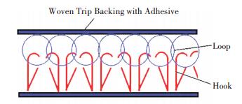
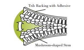
2 Experimental Procedures 2.1 Material and PreparationThe Velcro® used in this study is Scotch General Purpose Fasteners RF7721 produced by 3M, with a 25.4 mm width and a 1.21 m length. A couple of Velcro® consists of two parts with different surfaces with strong adhesive backings that are adhered to the substrate, one surface with hooks, and the other surface with loops. The scheme of the Velcro® fastener is shown in Fig. 1. The Dual-lock used in this study is CommandTM Picture Hanging Strips produced by 3 M, which is 18 mm in width and 50 mm in length, as shown in Fig. 2. A couple of Dual-lock consists of two linked identical structures, each surface of which contains hundreds of mushroom-shaped stems to form a secured attachment with strong adhesive backings that adhered to the substrate.
|
Fig.1 Scheme of Velcro® fastener |
|
Fig.2 Scheme of Dual-lock fastener |
2.2 Specimens Assemblies
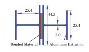
The Velcro® and Dual-lock fasteners with strong adhesive backings were cut to 50 mm in length and then bonded to the specific aluminum substrate. The adhesive bonded joints are much stronger than the Velcro® or the Dual-lock fastener attachment, so that external load can pull the Velcro® and Dual-lock fasteners apart before the debonding or failure of the adhesively bonded joints. To investigate the mechanical behaviors of the Velcro® and Dual-lock fastener separations, specific aluminum adherends were employed[20]. In the transaction area, the widths of the two flanges are 25.4 mm and 44.45 mm, respectively, the height is 25.4 mm. The long I-beam was cut to 50 mm in length. The configuration of the specimen and the dimension of the aluminum adherend are shown in Fig. 3. This specific aluminum adherend strongly reduces the effects of stress singularities due to edge effects[21]. The bonding surfaces of the adherends were polished using 220# sand paper prior to the bonding processes. This can ensure smooth and unique surface roughness. Acetone was used to clean the dusts and residual oil on the bonding surfaces. Velcro® and Dual-lock fasteners were bonded in the middle of the substrate in order to ensure good positioning during the bonding process and alleviate stress concentration[22].
|
Fig.3 Configuration of specimen and dimensions of aluminum adherends |
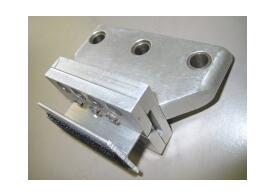
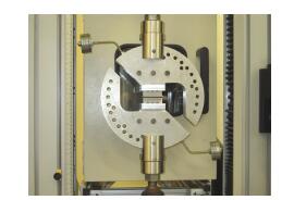
A modified Arcan was employed to perform the tensile and shear experiments[20]. Fig. 4 and Fig. 5 present the specific clamp and the assembly of the specimen in the modified Arcan fixture, respectively.
|
Fig.4 Scheme of the clamp designed for the aluminum adherend |
|
Fig.5 Assembly of the specimen in the modified Arcan fixture |
The DCB specimens bonded by the Velcro® and Dual-lock fasteners were prepared, as shown in Fig. 6. For Velcro® specimens, a=50 mm, l=250 mm, h=12.75 mm, d=2 mm, and w=25.4 mm; for Dual-lock specimens, a=20 mm, l=100 mm, h=2.54 mm, d=2 mm, and w=18 mm. The adherends of the DCB specimen was made of T6061 aluminum alloy. Yielding of the adherends was avoided during the tests, so that linear elastic homogenous isotropic material properties were used in the analysis. Prior to the bonding, the surfaces of the aluminum adherends were the same treatments as above. For the specimens used in the 180° peel tests, the Velcro® and Dual-lock fasteners with adhesive backings were cut to 50 mm in length and bonded to thin PE (polyethylene) film. The PE films are strong enough to withstand the tensile deformation in the tests, which were griped in the pneumatic clamps of the testing machine. The thickness of the PE film is 0.5 mm. The dimensions and configuration of the specimen are shown in Fig. 7, with l=50 mm, h=0.5 mm, d=2 mm, and R=1.5.

|
Fig.6 Configuration and dimensions of the DCB specimen |

|
Fig.7 Configuration and dimensions of the 180° peel test specimen |
2.3 Experiments
The experiments were executed on a mechanical testing machine, Instron 5800. The monotonic tensile, shear, and mixed tensile-shear with loading angles of 30°, 45°, and 60° tests were conducted using a load cell with the maximum load of 5 kN and the crosshead displacement rate of 10 mm/min. The effects of loading rates were investigated by using the crosshead speed at 0.1, 1, 10, 20, 50 and 100 mm/min, respectively. The DCB tests were conducted using a 1 kN load cell, with the crosshead displacement rate of 10 mm/min. The 180° peel tests were conducted using the same test machine with a 50 N load cell and the crosshead displacement rate is 10 mm/min. The assembly of specimens followed a rigorous and identical procedure. Each test was repeated five times using new specimens.
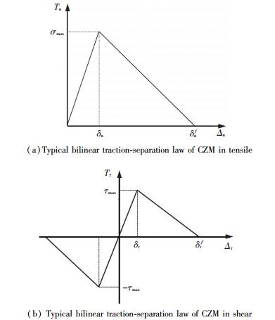
3 Simulations Using CZM 3.1 Cohesive ElementThe CZM traction-separation laws are commonly used to model delamination in adhesively bonded joints. The Velcro® and Dual lock fasteners, which act as mechanical adhesive, are similar to adhesively bonding joints. Therefore, it would be interesting to use the CZM to describe the initial and propagation of separation of the two fasteners attachment. When characterizing their behaviors, traction-separation law is required, which can be established using two critical parameters: cohesive stress (or maximum traction), and fracture energy. In the present work, a simple shape of bilinear traction-separation law is selected. The cohesive constitutive relations for the bilinear CZM are given as follows.
| $ T_{n}=\left\{\begin{array}{ll}{\frac{\sigma_{\max }}{\delta_{n}} \Delta_{n}, } & {\Delta_{n} \leqslant \delta_{n}} \\ {\sigma_{\max } \frac{\left(\delta_{n}^{f}-\Delta_{n}\right)}{\left(\delta_{n}^{f}-\delta_{n}\right)}, } & {\Delta_{n}>\delta_{n}}\end{array}\right. $ | (1) |
| $ T_{\tau}=\left\{\begin{array}{ll}{\frac{\tau_{\max }}{\delta_{\tau}} \Delta_{n}, } & {\Delta_{\tau} \leqslant \delta_{\tau}} \\ {\tau_{\max } \frac{\left(\delta_{\tau}^{f}-\Delta_{\tau}\right)}{\left(\delta_{\tau}^{f}-\delta_{\tau}\right)}, } & {\Delta_{\tau}>\delta_{\tau}}\end{array}\right. $ | (2) |
To distinguish the tensile law from the shear one, let the subscript 'n' represent the normal direction while 'τ' denote the shear direction. T is the traction. The maximum value of Tn is σmax, and the maximum value of Tτ is τmax. Where σmax and τmax are the maximum normal stress and tangential stress, respectively; δn and δτ are the normal and tangential separations when the maximum normal stress or tangential stress reaches its peak value, respectively; δnf and δτf are the critical normal and tangential separations when complete separation occurs. Fig. 8 presents the traction-separation law of the CZM, with Fig. 8(a) and 8(b) representing the relations in tensile and shear direction, respectively. The normal and tangential works of separation are given by
| $ G_{n}=\frac{1}{2} \sigma_{\max } \delta_{n}^{f} $ | (3) |
| $ G_{\tau}=\frac{1}{2} \tau_{\max } \delta_{\tau}^{f} $ | (4) |
|
Fig.8 Typical bilinear traction-separation law of CZM in tensile and shear |
3.2 Numerical Simulations
The CZM in continuum mechanics based on the energy concept is more appropriate to describe both separation initiation and propagation across the gap between two adjacent planes[23-24]. The numerical simulations of the separation of the two fasteners in the DCB and 180° peel tests were carried out with the aid of finite element method (FEM) in the commercial software ABAQUS. The attachment of fastener is defined as a thin layer that obeys the traction-separation law of CZM. Accordingly, the elements along this layer are defined as cohesive elements. Other material properties of the model are defined as normal. Based on the geometry of the specimens and the loading conditions, plane strain is assumed in the 2D simulations. In the numerical model, a typical 2D finite element mesh of the specimen was used. The Velcro® bonded DCB specimen includes 100 cohesive elements (COH2D4) and 1700 plane strain elements (CPE4R). The Dual-lock bonded DCB specimen includes 100 cohesive elements, and 920 plane strain elements, with the same element type as those for the Velcro® model. The Velcro® bonded 180° peel specimen includes 100 cohesive elements. The Dual-lock bonded 180° peel specimen includes 50 cohesive elements. Similarly, the other elements for adherends are CPE4R. The time increment in each step of the analysis is set small enough to ensure the convergence of the nonlinear simulation processes.
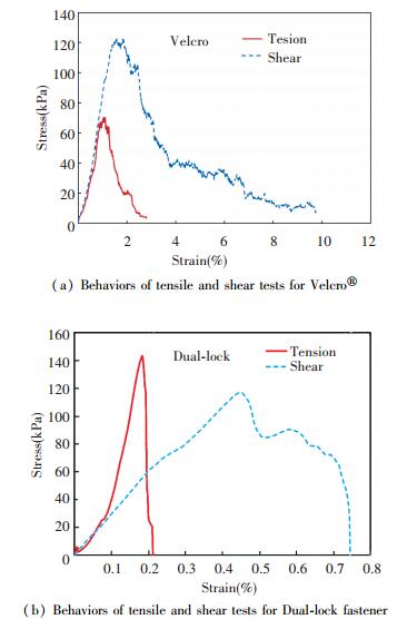
4 Result and Discussion 4.1 Behaviors Under Tensile and Shear LoadsThe mechanical behaviors of the Velcro® and dual-lock fasteners were obtained by the monotonic tensile and shear tests using the modified Arcan fixture, with the loading rate of 10 mm/min. The tensile and shear stresses evolved as a function of the strain for the Velcro® was graphed in Fig. 9(a). It is showed that the peak shear stress magnitude of the Velcro® specimens is much higher than its peak tensile stress. It can be explained that a hook on one side can continuously grip more loops on the opposite surface when it passes through in the direction parallel to the bonding surface than the one vertical to it. The fracture energy values in tensile and shear were obtained from the areas under the tensile and shear curves, and the tensile strain and the shear stain of Velcro® were also obtained from the experimental results. From the above mechanical parameters analysis, it is shown that the mechanical behaviors of the Velcro® fasteners demonstrate the ductile manner for this type of attachment.
|
Fig.9 Behaviors of tensile and shear tests for Velcro® and Dual-lock fastener |
For the Dual-lock specimens, the tensile and shear stresses evolution as a function of the strain was graphed in Fig. 9(b). It is showed that the peak tensile stress magnitude of the Dual-lock specimens is higher than its peak shear stress, which means that the Dual-lock fastener is more resistant to tensile loads than shear loads. The fracture energy of the tensile and the shear were obtained from the areas under the tensile and shear curves, respectively, and the tensile strain and the shear stain of the Dual-lock were also obtained from the experimental results. According to the Dual-lock fastener mechanical parameters analysis, it is shown that the mechanical behaviors demonstrate the brittle manner for this type of attachment. The experimental results show that some residual stress remains after it drops from the peak in the shear test of the Dual-lock fastener. The details will be discussed in Section 3.2. The mechanical parameters of the Velcro® and the dual-lock fasteners obtained from these experiments only aim at the ordinary commercial products. Nevertheless, there is little in the way of literature and product specifications to reference in order to evaluate this experimental data.
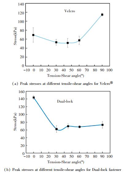
4.2 Influences of Load AnglesThe Velcro® and Dual-lock fastener specimens were tested with different tensile-shear mixed mode loading angles using the modified Arcan fixture and the adjustable balance weight. The comparisons of the peak stresses of the Velcro® fastener at different mixed mode loading angles are shown in Fig. 10(a). The results demonstrated that magnitudes of the peak stresses in 30°, 45°, and 60° have no significant difference, which are lower than those in the monotonic tensile or shear tests. This can be explained by the Velcro® hooks being arranged opposite to the loops, as shown in Fig. 1. The hooks direction would catch fewer loops in the mixed mode loading conditions than under tensile or shear conditions. The experimental results also confirmed that the shear strength of the Velcro® is relatively high as shown in the test results.
|
Fig.10 Peak stresses at different tensile-shear angles for Velcro® and Dual-lock fastener |
The peak stresses of the Dual-lock fastener for the different mixed mode loading angles were graphed in Fig. 10(b). The results showed that the peak stress in the monotonic tensile test is high when comparing it with that tested at different mixed mode loading angles. The reason is that a head of mushroom of the Dual-lock can simultaneously interact with two neighbor mushroom heads in the tensile tests. However, in the mixed mode tensile-shear loading angles, the head of mushroom can only interact with the one side of the mushroom head where loading direction is not vertical to the stem of mushroom, so that the interaction forces are reduced. Fig. 11 shows the scheme of the interaction of the mushroom heads of the Dual-lock fastener at the separation process for the different mixed mode loading angles. It is evident that the experimental data scatters wildly. One dominant factor might be the uncertainty of the attachment surfaces, that is, it is not sure how many of the hooks and loops, or mushroom heads, in the specimens would be entangled together at one time.

|
Fig.11 Scheme of Dual-lock mushroom interaction when loaded in different angles |
4.3 Influences of Loading Rates
In order to understand the influences of loading rates on the attachment strength of the Velcro® and Dual-lock fasteners, various loading rates of the tensile and shear were applied such as 0.1, 1, 10, 20, 50 and 100 mm/min, respectively. Plots of the experimental data are shown in Fig. 12(a). The results of the Velcro® specimen show that the peak stresses increases when the loading rate increases from 1 to 20 mm/min in the tensile test. For the shear test, the peak stress increases when the loading rate increases from 0.1 to 1 mm/min. The peak tensile and shear stresses drop when the loading rate exceeds 20 mm/min. Therefore, Velcro® has good performance and the attachments are relatively strong at the loading rate of 10 to 20 mm/min in the tensile and shear condition.
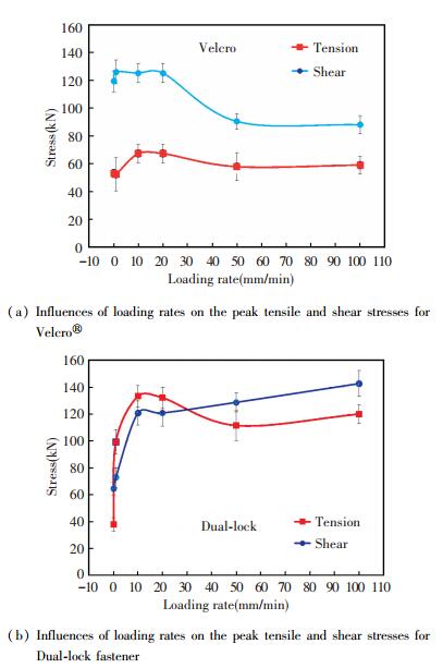
|
Fig.12 Influences of loading rates on the peak tensile and shear stresses for Velcro® and Dual-lock fastener |
The effects of the different loading rates on the Dual-lock fastener attachment strength in the tensile and shear are shown in Fig. 12(b). The peak stress increases when the loading rate increases from 0.1 to 10 mm/min in the tensile test, then the peak stress drops when the loading rate increases from 20 to 100 mm/min. The peak stress rises when the loading rate increases from 0.1 to 100 mm/min in the shear test, though the values are almost equal when the loading rates are at 10 and 20 mm/min. It means that the tensile strength of the Dual-lock fastener has good performances at the loading rate 10 to 20 mm/min, and the shear strength increases with the loading rate increase.
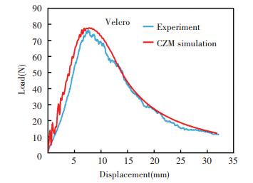
4.4 DCB Experiments and CZM SimulationsOne of the load-displacement curves of the Velcro® attachment DCB specimens separation obtained from the tests is shown in Fig. 13. It is observed from the tests that the Velcro® attachment separation takes place gradually after the initiation and there are some loops tangled with the loops after the substrate separation. The separation behavior of the Velcro® fastener is similar to the fracture process of the ductile materials.
|
Fig.13 Load-displacement curves for the DCB specimen of the Velcro® |
A bi-linear CZM was employed to simulate the Velcro® fastener separating propagation. The key parameters of the CZM include cohesive stress (tensile and shear), fracture energy, and the characteristic length parameter. Those parameters of the Velcro® fasteners were obtained from the tensile and shear experimental results; the characteristic length was obtained from the actual distance of the two hooks of the Velcro® fasteners, as shown in Table 1. The comparisons of the numerical and experimental results also show that the magnitude of simulated load is larger than the experimental one. The reason is that the CZM parameters calculated from the tensile and shear tests did not consider the stiffness of the fasteners. It is reasonable that real fasteners are more flexible due to the separation of the hooks and loops and the deformation of the soft backing adhesive layers.
| Table 1 Cohesive zone model parameters for the two fasteners |
Most of the curves obtained from the simulations are reasonably smooth. However, there is significant oscillation in the initial stage of the delamination. One possible reason would be that the maximum traction is small when comparing to the reaction force/stress of the adherends, inducing numerical instability in the simulations with the CZM.
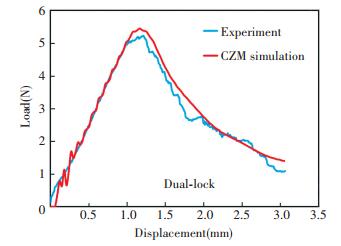
For the Dual-lock fastener attachment DCB specimens, the load-displacement curves from experiments and simulations are shown in Fig. 14. It is observed in the tests that the substrate separation takes place abruptly after delamination initiation, and there are not mushroom tangled with others after the separation. The fracture behaviors of the Dual-lock fastener specimen are similar to those of brittle materials.
|
Fig.14 Load-displacement curves for the DCB specimen of the Dual-lock |
The CZM was also used to simulate the Dual-lock fastener separating propagation. The key parameters of the CZM were obtained from the tensile and shear experiments, and the characteristic length was obtained from the actual distance of the tow mushroom-shaped stems of the Dual-lock fastener, as shown in Table 1. The numerical results show that the initial separation agrees well with the experimental results, though the experimental load-displacement curve is lower than the numerical curve due to the uncertainty of the separating processes. It is demonstrated that the bilinear CZM is more suitable for modeling the analogous brittle material separation processes of the Dual-lock fastener.
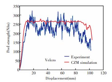
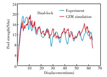
4.5 Peel Experiments and CZM SimulationsThe peel test is another method to study the attachment strength characteristics of Velcro® and Dual lock fasteners. In the present work, the peel strength is defined as the load per unit width of one specimen. Fig. 15 shows the evolution of the peeling displacement against the peeling strength for the Velcro®. It is showed that the peeling strength increases gradually and then keeps the value at about 250 N/m and then decreases gradually to a low level until the final break. In the peel tests, it can be observed that the number of loops removed from one hook of Velcro® fastener is not constant. Therefore, the value of peel strength changes randomly. The evolution of the peeling displacement against the peeling strength for the Dual-lock is shown in Fig. 16. It is demonstrated that the peeling strength increases and then decreases gradually to a low level until the final break. The test curve fluctuates up and down regularly, since the separation of mushroom-shaped stems of the Dual-lock fastener from each other is discrete but regular in the peel tests. It can be observed from the test results that Velcro® fasteners are stronger in peeling tests when compared to the Dual-lock fasteners.
|
Fig.15 Evolution of peel strength as function of displacement for Velcro® |
|
Fig.16 Evolution of peel strength as function of displacement for Dual-lock |
The parameters used in the simulations of the peeling tests of the two fasteners with the CZM are as same as those used in the simulations of the DCB tests. For the Velcro® fasteners, the comparison of the numerical and experimental results demonstrates that the CZM calculation curve fit to the experimental data from the separation initiation to the entire separation. Although the element size (0.05 mm) is small enough, it is difficult to capture the hooks and loops of the Velcro® fasteners which are irregular and dense, so that the calculation curve does not fluctuate like the experiments. While the CZM simulates the Dual lock fastener peeling test, the cohesive elements size (0.35 mm) were adopted, so it can capture the Dual lock fastener peeling separation very well. It is seen that the calculated curves from the bi-linear CZM agree comparatively well with the experimental curve for the entire separation processes, from initiation to propagation along the interface. Based on the above analyses, the bi-linear CZM is arguably more suitable for simulating the two fastener separations.
5 ConclusionsThe mechanical behaviors of the Velcro® and Dual-lock fasteners were investigated using the modified Arcan fixture and a specifically designed clamping system. The basic parameters of the Velcro® and Dual-lock fasteners such as elastic stiffness (similar to Young's modulus for bulk material), cohesive stress, and fracture energy were obtained from the tensile and shear experiments. The experimental results showed that the shear stress is higher than the tensile stress for the Velcro® fastener. However, the tensile stress is lower than the shear stress for the Dual-lock fastener. The magnitudes of the peak stresses of the Velcro® at the loading condition of mixed mode tension-shear of 30°, 45° and 60° are similar, which are lower than those from the tensile or shear tests. The two fasteners perform well under the loading rate of 10-20 mm/min, with the performance of the Dual-lock fastener being better at a high loading rate either in the tensile or shear conditions. The mechanical behaviors of the Velcro® show that it is flexible and can still hold some stress after reaching peak stress. The Dual-lock fastener shows that it is more brittle than the Velcro® one.
The DCB tests and the peel tests of the Velcro® and Dual-lock fasteners specimens were conducted to characterize the structural strength of the attachments. The CZM with the bi-linear traction-separation laws was adopted to simulate initiation and propagation of the two fasteners separations. It is shown that the CZM is very suitable to describe the two fasteners separating processes in the DCB fracture and the peel tests. The comparisons demonstrate that the CZM calculation can capture the Dual lock fastener peeling separation very well with respect to the experimental curve fluctuating regularly. The theoretical research approach provides an effective tool for more extensive applications of the Velcro® and Dual-lock fasteners. The results demonstrated some interesting behaviors and would be useful in engineering designs and effective applications of the Velcro® and Dual-Lock fasteners.
| [1] |
George De Mestral. Velvet type fabric and method of producing same. U.S. Patent No.2717437.United States Patent Office. 1951.
(  0) 0) |
| [2] |
Meyers M A, Chen P-Y, Lopez M I, et al. Biological materials: A materials science approach. Journal of the Mechanical Behavior of Biomedical Materials, 2011, 4(5): 626-657. DOI:10.1016/j.jmbbm.2010.08.005 (  0) 0) |
| [3] |
Flores E I S, Friswell M I, Xia Y. Variable stiffness biological and bio-inspired materials. Journal of Intelligent Material Systems and Structures, 2012, 24(5): 529-540. DOI:10.1177/1045389X12461722 (  0) 0) |
| [4] |
Jagota A, Hui C-Y. Adhesion, friction, and compliance of bio-mimetic and bio-inspired structured interfaces. Materials Science and Engineering:R:Reports, 2011, 72(12): 253-292. DOI:10.1016/j.mser.2011.08.001 (  0) 0) |
| [5] |
Bader D L, Pearcy M J. Material properties of Velcro® fastenings. Prosthetics and Orthotics International, 1982, 6(2): 93-96. (  0) 0) |
| [6] |
Gorb S N, Popov V L. Probabilistic fasteners with parabolic elements: Biological system, artificial model and theoretical considerations. Philosophical Transactions of the Royal Society A, 2002, 360(1791): 211-225. DOI:10.1098/rsta.2001.0926 (  0) 0) |
| [7] |
Chen Q, Gorb S, Gorb E, et al. Mechanics of plant fruit hooks. Journal of Royal Society Interface, 2013, 10(81): 20120913. DOI:10.1098/rsif.2012.0913 (  0) 0) |
| [8] |
Gorb S N. Biological attachment devices: Exploring nature's diversity for biomimetics. Philosophical Transactions of the Royal Society A, 2008, 366(1870): 1557-1574. DOI:10.1098/rsta.2007.2172 (  0) 0) |
| [9] |
Han H, Weiss L E, Reed M L. Micromechanical Velcro®. Journal of Microelectromechanical Systems, 1992, 1(1): 37-43. DOI:10.1109/84.128054 (  0) 0) |
| [10] |
Pugno N M. Velcro® nonlinear mechanics. Applied Physics Letters, 2007, 90(12): 775-779. DOI:10.1063/1.2715478 (  0) 0) |
| [11] |
Barenblatt G I. The formation of equilibrium cracks during brittle fracture: general ideas and hypotheses. Axially- symmetric cracks (O ravnovesnykh treshchinakh obrazuiushchiksia pri krupkom razrushenii. OPbshchie predstavleniia i gipotezy. Osesimnetrichnye treshchiny)v. Journal of Applied Mathematics and Mechanics, 1959, 23(3): 622-636. DOI:10.1016/0021-8928(59)90157-1 (  0) 0) |
| [12] |
Dugdale D S. Yielding of steel sheets containing slits. Journal of the Mechanics and Physics of Solids, 1960, 8(2): 100-104. DOI:10.1016/0022-5096(60)90013-2 (  0) 0) |
| [13] |
Needleman A. An analysis of decohesion along an imperfect interface. International Journal of Fracture, 1990, 40(1): 21-40. (  0) 0) |
| [14] |
Tvergaard V, Hutchinson J W. The relation between crack growth resistance and fracture process parameters in elastic-plastic solids. Journal of the Mechanics and Physics of Solids, 1992, 40(6): 1377-1397. DOI:10.1016/0022-5096(92)90020-3 (  0) 0) |
| [15] |
Yan Y, Shang F. Cohesive zone modeling of interfacial delamination in PZT thin films. International Journal of Solids and Structures, 2009, 46(13): 2739-2749. DOI:10.1016/j.ijsolstr.2009.03.002 (  0) 0) |
| [16] |
Zavattieri P D, Espinosa H D. Grain level analysis of crack initiation and propagation in brittle materials. Acta Materiallia, 2001, 49(20): 4291-4311. DOI:10.1016/S1359-6454(01)00292-0 (  0) 0) |
| [17] |
Feraren P, Jensen H M. Cohesive zone modelling of interface fracture near flaws in adhesive joints. Engineering Fracture Mechanics, 2004, 71(15): 2125-2142. DOI:10.1016/j.engfracmech.2003.12.003 (  0) 0) |
| [18] |
Zhang Z(Jenny), Paulino G H. Cohesive zone modeling of dynamic failure in homogeneous and functionally graded materials. International Journal of Plasticity, 2005, 21(16): 1195-1254. DOI:10.1016/j.ijplas.2004.06.009 (  0) 0) |
| [19] |
Park K, Paulino G H, Roesler J R. Determination of the kink point in the bilinear softening model for concrete. Engineering Fracture Mechanics, 2008, 75(13): 3806-3818. DOI:10.1016/j.engfracmech.2008.02.002 (  0) 0) |
| [20] |
Zhang J, Jia H. Influence of cohesive zone models shape on adhesively bonded joints. Chinese Journal of Theoretical and Applied Mechanics, 2016, 48(5): 1088-1095. DOI:10.6052/0459-1879-16-064 (  0) 0) |
| [21] |
Cognard J Y. Numerical analysis of edge effects in adhesively- bonded assemblies application to the determination of the adhesive behavior. Computers and Structures, 2008, 86(17-18): 1704-1717. DOI:10.1016/j.compstruc.2008.02.003 (  0) 0) |
| [22] |
Cognard J Y, Davies P, Sohier L, et al. A study of the non-linear behaviour of adhesively-bonded composite assemblies. Composite Structures, 2006, 76(1/2): 34-46. DOI:10.1016/j.compstruct.2006.06.006 (  0) 0) |
| [23] |
Créac'hcadec R, Jamin G, Cognard J Y, et al. Experimental analysis of the mechanical behaviour of a thick flexible adhesive under tensile/compression-shear loads. International Journal of Adhesion and Adhesives, 2014, 48(1): 258-267. DOI:10.1016/j.ijadhadh.2013.09.040 (  0) 0) |
| [24] |
Cuminatto C, Braccini M, Schelcher G, et al. Mechanical resistance of patterned BCB bonded joints for MEMS packaging. Microelectronic Engineering, 2013, 111(4): 39-44. DOI:10.1016/j.mee.2013.05.012 (  0) 0) |
 2019, Vol. 26


