2. National Engineering Research Center for Advanced Polymer Processing Technology, Zhengzhou University, Zhengzhou 450002, China;
3. School of Mathematics, Sun Yat-sen University, Zhuhai Campus, Zhuhai 519082, China
Carbon fiber (CF) reinforced thermoplastic composites (TPCs) have been used widely in marine, aerospace, and automobile industries because of their strong specific strength, high rigidity, light weight, and superior fatigue resistance[1-3]. However, CF presents poor wettability and it is adhesive to the matrix of thermoplastics due to its chemical inertness and low surface free energy. The application of TPC is restricted by poor wettability and the interfacial bonding strength (IBS) between the fiber and the matrix[4-5]. Thus it is a challenge for scientists to obtain good wettability and high IBS for industrial applications.
In this paper, controlled amounts of carbon nanotubes (CNTs) were grafted onto the surface of CF to prepare the hybrid reinforcement (HR). We used HR to fabricate PA6 composites by a new process named three-dimensional printed molding (3D-PM) which integrates 3D printing into compressive molding process. A molten-drop of PA6 was printed onto different modified fibers to evaluate the wettability between the fibers and the matrix PA6 based on the changes in the contact angles. The main purposes of the paper are to investigate the relationships among surface morphology of the fibers, IBS, and the mechanical properties of the composites, and to find a method to improve the properties of TPC.
Studies that focus on the improvement of the IBS presented different methods to modify CF, such as oxidation treatments, interphase tailoring via sizing/coating on fibers, creation of hierarchical fibers by nanostructures, fiber surface modifications by polymer deposition, and potential effects of matrix modifications on the interphase formation[6-11]. Through oxidation, the decrease of roughness value may cause the decrease of the micro-cracks of the CF surface and the weakening of the stress concentration of the fiber[6]. Moon et al.[12]reported that the oxidization treatment of CF in an aqueous medium containing ammonium bicarbonate results in improved IBS but reduces tensile strength of several types of CFs. Sizing treatment by epoxy on CF is one of the most popular modification processes[13]. The presence of epoxy sizing agent could improve the adhesion between the fiber and thermoset matrix. Major reasons for the improved interfacial adhesion are the increased van der Waals forces between the matrix and the sizing layers as well as the chemical bonding between the sizing layers. When the epoxy sizing decomposes at about 250 ℃, it is not suitable for TPC. Meng and Ma et al.[14-15] showed that the grafting of branched polyethyleneimine on the CF surface can increase the polarity, wettability, and CF surface roughness. The polymer works as a shielding layer to relieve the stress concentration and prevent the crack tips from contacting the fiber surface directly and causing the crack path to deviate away from the fiber surface to the interphase region[16].These grafting techniques have provided valuable improvements in composite properties: up to 47.1% in impact strength and 82.6% in fracture resistance. Apart from grafting polymer, grafting nanoparticles (such as CNTs) have been used to improve IBS of the composites in recent years[17-19]. Because of the good conductivity of CNT, the process of grafting CNT into CF is also used to improve the electrical properties of composites[20-21]. Romhany[22] revealed that the crack propagation at the interface is forced to follow a zig-zag route owing to the intervention of the CNT, which leads to the increase of energy dissipation of crack growth. Methods of grafting CNT onto CF include chemical vapor deposition (CVD), electro-deposition, and chemical grafting, etc.[23-27] For CVD, grafting usually takes several hours, which is not practical to the industrial mass production[23].The method of electro-deposition is helpful for dispersing CNT uniformly, but it weakens the mechanical properties of CF[24]. The chemical grafting excels at its high bonding strength and simple operation, while there is a limited number of CNTs grafted and the process often causes serious pollution[25]. The grafting with coupling agents has been tested to be practical in industrial applications[28-29]. Zhao[16, 28] used a coupling agent containing polyhedral oligomeric silsesquioxanes to graft CNT onto CF. Lv[17] proposed a beneficial novel method to uniformly graft high-density CNTs onto CFs by using coupling agents, which can supply much more active groups. Zhang[30] indicated that the crack propagation is significantly affected by the presence of CNT, which can effectively hinder the crack propagation and strengthen the fiber/matrix interface.
Although the process of grafting CNT onto CF surface has been studied extensively, there are several important questions to be answered which include how to associate the amount of grafted CNT with the properties of the interface, and how to describe the quantitative relationship between grafted CNT and IBS of the composites, especially for TPC.
2 Materials and Experiments 2.1 MaterialsCFs (12K, T300, tensile strength 3500 MPa, and 7 μm in diameter) used in the study were provided by Energy and Chemical Industry Research Institute of Henan. High purity CNTs were supplied by Chengdu Organic Chemistry Corporate in China. The average dimension of the CNTs is 30 nm in diameter and 10-30 μm in length. The matrix used is resin PA6 from Dupont, and it has a density of 1.14 g/cm3, a melting temperature of 220 ℃, a tensile strength of 65 MPa, a Young's modulus of 2.600 GPa, and a tensile breaking elongation of 26%.
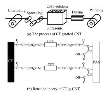
2.2 Preparation and Analysis on CF Grafted by CNT (CF-g-CNT)The CFs were heated to 380 ℃ in a Muffle furnace for 10 min to remove impurity in their surfaces(CF-p). They were oxidized with 70% nitric acid solution to improve the grafting reaction, washed with deionized water and ethanol assisted with sonicating, and dried with hot wind. The oxidized CFs reacted with 3-a minopropyltriethoxysilane(APS) at 60 ℃ to obtain functionalized CF(CF-f). 10 g CNTs were oxidized in 70% HNO3 solution at 70 ℃ for an hour assisted with sonicating. The oxidized CNTs were collected by suction filtration using Hirsch funnel, washed thoroughly with deionized water, and dried for 2 h at 120 ℃. The CNTs were then dispersed into APS solution to form a CNT-solution. CF-f reacted with the CNT-solution for 10-30 min under sonicating to obtain CF-g-CNT. The grafting and the reaction processes used to prepare CF-g-CNT are shown in Fig. 1.
|
Fig.1 The grafting process to prepare CF-g-CNT |
By controlling grafting reactive time, we obtained CF-g-CNT reinforcements with three samples of CNTs. Evaluation of the CF mass before and after grafting revealed that the rates of grafted nanotubes were about 0.1%, 0.25%, and 0.4% in mass. In order to get the accurate weight fraction of CNT, organic residue on the surface of CF was removed with nitric acid solution.
The contact angle of the fiber with the resin was measured with an Optical contact angle meter(Krüss, DSA100 with external tilting table PA3220). Morphology of CF-g-CNT was observed with Q7 Quanta FEG 250 Scanning Electron Microscope (SEM). The surface functional groups of different modified CFs were analyzed by FTIR spectrophotometer (Nicolet, Nexus670, USA) using powder-pressed KBr pellets. The FTIR spectra were acquired by scanning the samples for 64 times in the wave number range of 400-4000 cm-1 with the resolution of 2 cm-1. In addition to FTIR, XPS technique (Thermofisher, GBR) was used to analyze the surface functional groups of the CFs. The obtained spectra were evaluated using the software package provided by the system manufacturer. The hemispherical analyzer of the system was operated in the CAE-mode with pass energy of 200 eV for the survey spectra and 20 eV for the high resolution spectra, corresponding to the maximum of the half-peaks to Ag3d5/2 reference peak 2.52 eV and 0.63 eV, respectively. Standard charge shift referencing via the C1s peak of an aliphatic carbon at 284.6 eV was applied.
A hydraulic-controlled testing system(MTS: Landmark 100 kN) was used for the mechanical test. Five tensile and five three-point-bending tests were conducted for evaluating the tensile and flexural stiffness and the strength of the laminates. The tensile, following ASTM standards and the velocity in the test, was controlled as constant at 0.5 mm/min in every test condition.
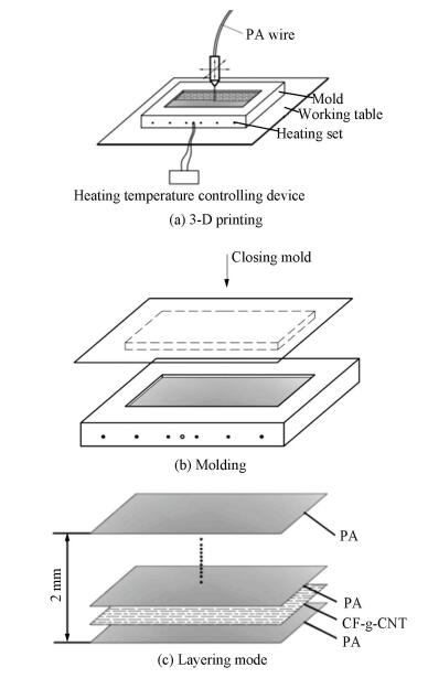
2.3 3D-PM to Prepare CF-g-CNT/PA6 CompositesCF-g-CNT reinforced PA6 composites were fabricated with the 3D-PM. Compared with the conventional hot-press of stacked thermoplastic membrane, 3D-PM is beneficial for forming complex parts and improving the wettability between CF and matrix, which is a new technique to eco-friendly fabricate small batch parts. The process is shown in Fig. 2. The main steps are as follows:
1) The mold with the heating device was placed on the work table of the 3D-printer, and the mold temperature was set to 150 ℃;
2) PA6 was printed to form the first layer resin substrate in the mold cavity under 180 ℃ printing temperature. The thickness of the printed PA6 layer was 0.2 mm. The nozzle diameter of the printer was 3.0 mm;
3) CF-g-CNT was placed on the PA6 layer, and the PA6 was printed again to form the cover layer on the surface of CF-g-CNT. The rest of the composites laminates could be done in the same way till they were 2 mm in thickness;
4) The mold was taken down the work table of the 3D-printer and was moved to the hot-press machine to compress. The compressing pressure was set to 3 MPa and the pressure holding time was 60 s;
5) The last step was to cool and eject the part from the mold cavity. The entire manufacturing process is shown in Fig. 2.
|
Fig.2 Schematic of the 3D-PM |
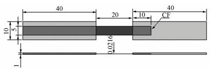
H-type sample used to measure the IBS, as shown in Fig. 3, was made by using the same process. The H-sample has a 5 mm-wide CF strip embedded in two PA6 resin bricks of 40 mm long, 10 mm wide, and 1 mm thick. The 5 mm CF strip is embedded fully in the left brick and partially in the right brick. The volume content of the CF in the H-sample is 60%.
|
Fig.3 H-sample for IBS test(unit:mm) |
According to the pulling force F of the CF out the matrix, the IBS, τi, can be calculated by the following formula:
| $ \tau_{i}=\frac{F}{\pi d l} $ | (1) |
where d is the diameter of a single fiber, l is the contact length of the fiber with the matrix. The single bundle of CF was expanded to 5 mm and the embedded length (l) was 10 mm.
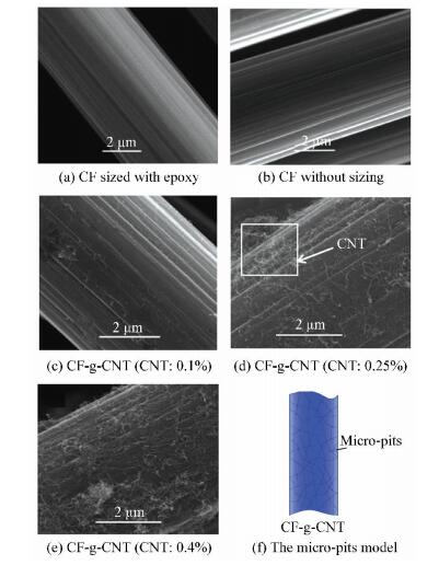
3 Results and Discussions 3.1 Analysis on CF-g-CNTIn order to evaluate the effects of CF-g-CNT on the interfacial microstructure of the composites, CF sized epoxy, purchased CF without sizing, and CF grafted by different weight fraction of CNTs were used to fabricate the composites. The surface microstructures of the tested CFs were observed by SEM, as shown in Fig. 4.
|
Fig.4 Morphology of different CFs and grafted CF surface micro-pits models |
Fig. 4(a) is the morphology of commercially available CF sized by 0.1 μm thick epoxy (data provided by the manufacturer). Fig. 4(b) is the morphology of CF without sizing, where surface grooves can be seen clearly. These grooves increase the surface area and surface energy of CF, which enhance mechanical interaction between PA6 and CF. Figs. 4(c), 4(d), and 4(e) are the microstructures of CF-g-CNT with weight fractions of CNTs of 0.1%, 0.25%, and 0.4%, respectively. In order to verify the amount of CNT weight fractions and the bonding strength between CNT and CF, the grafted CF was etched with nitric acid to remove the organic residues of the grafting reaction. Figs. 4(c), 4(d), and 4(e) show that the CNTs are uniformly distributed on the surface of the CF after etching, which indicates that strong bonding exists between CF and CNT. In particular (see Figs. 4(d) and 4(e)), it forms a network structure on the surface of CF, which alters the surface of the groove morphology to micro-pits, as shown in Fig. 4 (f). A critical amount of CNTs could form micro-pits morphology on the surface of CF, which could prevent the crack propagation at the interface and redirect the crack growth towards the matrix. In addition, stiff CNT network redirects the crack growth towards the matrix, which would absorb more deforming energy before fracture.
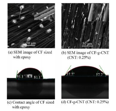
It is necessary to obtain good wettability between the matrix and CFs to realize the strengthening function of CNTs. In order to gauge the wettability, resin melt droplet was printed on the surface of CF. The morphology of the droplet on the surface of CF was observed by SEM and Optical contact angle meter, and the contact angles between PA6 and CF(without sizing) and between PA6 and CF-g-CNT were measured. The results are shown in Fig. 5. It can be seen from Figs. 5 (c) and 5(d) that the contact angle between PA6 droplet and CF without sizing is about 81.1 °, and it is almost 57.7 ° between CF-g-CNT and PA6 droplet, which indicates that the surface micro-pits can improve the interfacial wettability due to the capillary effect and high surface energy of CF.
|
Fig.5 Wettability between the fibers and the matrix |
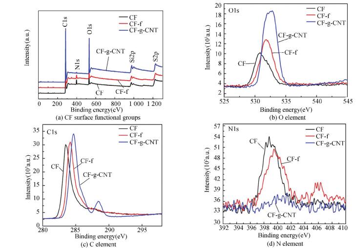
CF surface functional groups were analyzed by XPS technique, and the results are shown in Fig. 6. The XPS test found that the CF surface mainly consisted of C, O, and N elements. After being modified with 3-aminopropyltriethoxysilane and then with CNT, the content of C=O bond increased distinctly and the oxygen-containing functional group was introduced on the surface of CF. C1s and O1s peaks were enhanced, which indicates that CNT has been grafted onto the CF surface.
|
Fig.6 XPS results for different CFs |
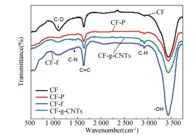
In order to gain more insights into the surface condition of CF, drift mode FTIR was employed to analyze the surface functional groups of CF. Fig. 7 shows that all samples clearly present three peaks with absorptions at approximately 3 420 cm -1, 1 630 cm -1, and 1 080 cm-1, corresponding to the -OH, C=C, and C-O bonds, respectively. In contrast to these two sets of CF-p and CF-f, it is easily seen that the peaks at 3 420 cm-1 and 1 080 cm-1 became stronger in CF-f, which implies that the functionalized CF surface is grafted with hydroxyl functional groups. The enhanced peaks at 2 891cm-1 and 2 953 cm-1 in CF-f and CF-g-CNT attribute to symmetric and asymmetric CH2 respectively, suggesting that CF and CNT are grafted by chemical bonds. The peak at 1 288 cm-1 attributes to the C-N stretching vibration, and it still appears in CF-g-CNT after the grafting reaction.
|
Fig.7 FTIR results for different CFs |
3.2 IBS of the Composites
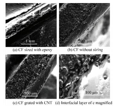
In order to study the interfacial bonding property of CF-g-CNT PA6 composites, we observed the microstructure of the cross-section of the 3D-PM without being pressed by SEM. Fig. 8(a) is the interfacial microstructure of the sample made by PA6 and CF without sizing reinforcement. The obvious crack at the interface can be seen in Fig. 8(a), which reveals that the adhesive force between fiber and the matrix is less than the cohesion of the matrix itself. Fig. 8(b) shows that CF-g-CNT presents good wettability with PA6. The continuous interfacial layer, 100 nm in thickness or around, is formed between CF-g-CNT and the matrix, as shown in Fig. 8(c). It can be inferred from Figs. 8(a) and 8(b) that the adhesion between CF-g-CNT and PA6 is close to the cohesion of PA6 itself, which allows melted PA6 to completely infiltrate into CF. The interfacial layer between the fiber and the matrix can alleviate the stress concentration induced by sudden change of the mechanical properties between the fiber and the matrix, and prevent the development of the interfacial flaws.
|
Fig.8 SEM image of 3D-printed smaples |
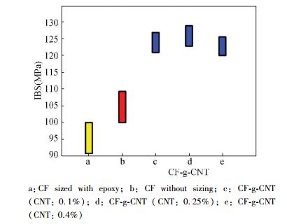
Furthermore, IBS was measured with H-type samples and the results are shown in Fig. 9. It can be seen that the IBS of CNT-g-CF reinforced PA6 is larger than those made by CF sized epoxy reinforced PA6 and CF-p reinforced PA6. When the weight fraction of CNT increases to 0.25%, the IBS strength of the composites increases by 20% compared with the ungrafted CF reinforced PA6 composites, and by 41.8% compared with the epoxy sizing CF reinforced PA6. However, IBS did not continue to increase when CNT weight fraction was higher than 0.4%.
|
Fig.9 IBS results for different CF composites |
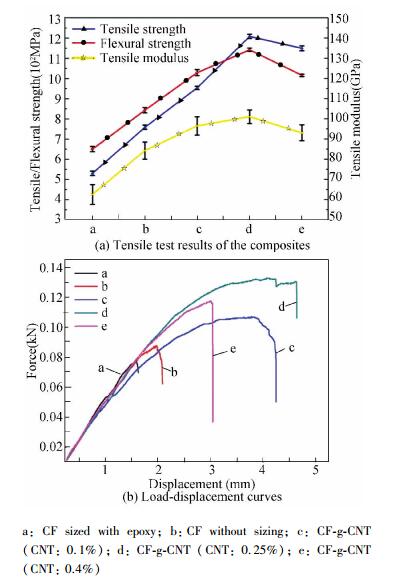
A similar trend was found in the tensile test results of the composites, as shown in Fig. 10. It is evident that the specimens fabricated using CF-g-CNT (CNT: 0.25%) have the highest average modulus and strength. The properties of the samples slightly decrease with the increase of CNT to 0.4%, as shown in Fig. 10. The interfacial shear strength (IFSS) can be calculated by the ratio of the peak force over the effective embedded CF surface area and estimated by the average embedded surface area of single CF. The calculated IFSS is 37.8, 59.8, 83.7, 128, and 97.3 MPa for H-samples a, b, c, d, and e, respectively.
|
Fig.10 Tensile test results of the composites and load-displacement curves measured for the H-samples |
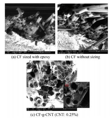
In order to clarify the stress transfer mechanism of CF-g-CNT hybrid enhanced thermoplastic composites, we observed the tensile fracture microstructures of several composites by SEM, as shown in Fig. 11. It can be seen from Fig. 11 that the removal of epoxy sintered from the matrix leaves a smooth void. In comparison, the interfacial bonding state of the uncured CF and the PA6 composite fracture surface is improved, as shown in Fig. 11(b). In the fracture of the composite material formed by CF-g-CNT and PA6 (Fig. 11(c)), the dimples in the matrix at the interface can be observed in the fracture microstructure of the composites, which indicates that the matrix resin undergoes a large plastic deformation before the fiber is withdrawn, which improves the fiber out resistance.
|
Fig.11 Tensile fracture morphology of different samples |
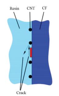
For CF-g-CNT hybrid reinforced PA6 composites, the stress transfer mechanism is shown in Fig. 12. When the micro-cracks of the interface were exposed to CNT on the surface of CF due to their high elasticity, the CNT prevented the cracks from spreading and forced it to turn inside the matrix. The propagation of the cracks in the matrix is related to the characteristics of the matrix. If the matrix is hard and brittle, crack propagation accelerates, which exacerbates the fracture of composite materials. If the matrix has a mild degree of flexibility, crack propagation slows down, which leads to better fracture resistance of the composite. When the matrix is overly flexible, however, it is easy to form tear cracks, which reduces the mechanical properties of the material, as demonstrated in Figs. 9-10. When the weight fraction of CNT is more than 0.4%, due to the strengthening effect of CNT on the resin matrix and the induced crystallization effect, the matrix becomes harder and more brittle, resulting in less desirable mechanical properties of the composite. The stress transfer mechanism and further analysis will be discussed in detail in another article.
|
Fig.12 Stress transfer model |
4 Conclusions
Different weight fractions of CNTs were grafted onto the CF surface by the coupling agent method. Effect of the weight fraction of CNTs on IBS and mechanical properties of HR/P A6 composites was studied by 3D-PM. Study results suggest that CNT can increase CF surface roughness and wettability. Comparing the composites with CF sized epoxy, the IBS increased by 41.8%, the tensile strength increased by 130%, and the interfacial shear strength by 238% as the weight fraction of CNT reached 0.25%. However, the IBS and the mechanical properties decreased, as the weight fraction of CNT continued increasing up to 0.4% because of rigid interfacial phase. CF grafted CNT reinforced thermoplastic composites by 3D-PM can be complied easily and shows great potential as a novel molding mode in high performance composites.
| [1] |
Friedrich K. Carbon fiber reinforced thermoplastic composites for future automotive applications. AIP Conference Proceedings. College Park: American Institute of Physics, 2016, 1736(1): 020001-1-020001-4. DOI:10.1063/1.4949575 (  0) 0) |
| [2] |
Gabrion X, Placet V, Trivaudey F, et al. About the thermomechanical behaviour of a carbon fibre reinforced high-temperature thermoplastic composite. Composites Part B: Engineering, 2016, 95: 386-394. DOI:10.1016/j.compositesb.2016.03.068 (  0) 0) |
| [3] |
Park S, Seo M. Carbon Fiber-Reinforced Polymer Composites: Preparation, Properties, and Applications. Thomas S, Kuruvilla J, Malhotra S K, et al. Polymer Composites: Volume 1. Weinheim: Wiley-VCH Verlag GmbH & Co. KGaA, 2012.40-41. DOI: 10.1002/9783527645213.ch5.
(  0) 0) |
| [4] |
Jing P Z, Zhu S, Mu-Huo Y U, et al. Preparation of carbon fiber fabric reinforced polyphenylene sulfide (CFF/PPS) thermoplastic composites based on surface modification of carbon fibers. Journal of Materials Engineering, 2016, 44(3): 21-27. DOI:10.11868/j.issn.1001-4381.2016.03.004 (  0) 0) |
| [5] |
Zhang Y, Zhang Y, Liu Y, et al. A novel surface modification of carbon fiber for high-performance thermoplastic polyurethane composites. Applied Surface Science, 2016, 382: 144-154. DOI:10.1016/j.apsusc.2016.04.118 (  0) 0) |
| [6] |
Liu J, Tian Y, Chen Y, et al. A surface treatment technique of electrochemical oxidation to simultaneously improve the interfacial bonding strength and the tensile strength of PAN-based carbon fibers. Materials Chemistry & Physics, 2010, 122(2-3): 548-555. DOI:10.1016/j.matchemphys.2010.03.045 (  0) 0) |
| [7] |
Yumitori S, Arao Y, Tanaka T, et al. Increasing the interfacial strength in carbon fiber/polypropylene composites by growing CNTs on the fibers. Wit Transactions on Modelling & Simulation, 2013, 55: 275-284. DOI:10.2495/CMEM130221 (  0) 0) |
| [8] |
Karger-Kocsis J, Mahmood H, Pegoretti A. Recent advances in fiber/matrix interphase engineering for polymer composites. Progress in Materials Science, 2015, 73: 1-43. DOI:10.1016/j.pmatsci.2015.02.003 (  0) 0) |
| [9] |
Ho K K C, Qian H, Bismarck A. Carbon Fiber: Surface Propertie. Nicolais L. Wiley Encyclopedia of Composites. Hoboken: John Wiley & Sons, Inc. 2011.35.DOI: 10.1002/9781118097298.weoc024.
(  0) 0) |
| [10] |
Yuan H, Zhang S, Lu C, et al. Improved interfacial adhesion in carbon fiber/polyether sulfone composites through an organic solvent-free polyamic acid sizing. Applied Surface Science, 2013, 279: 279-284. DOI:10.1016/j.apsusc.2013.04.085 (  0) 0) |
| [11] |
Sharma M, Gao S, Mäder E, et al. Carbon fiber surfaces and composite interphases. Composites Science & Technology, 2014, 102: 35-50. DOI:10.1016/j.compscitech.2014.07.005 (  0) 0) |
| [12] |
Moon C W, Jung G, Im S S, et al. Effect of anodic oxidation of H2SO4/HNO3 ratio for improving interfacial adhesion between carbon fibers and epoxy matrix resins. Polymer Korea, 2013, 37(1): 61-65. DOI:10.7317/pk.2013.37.1.61 (  0) 0) |
| [13] |
Zhang R L, Zhang J S, Zhao L H, et al. Sizing agent on the carbon fibers surface and interface properties of its composites. Fibers & Polymers, 2015, 16(3): 657-663. DOI:10.1007/s12221-015-0657-x (  0) 0) |
| [14] |
Meng L, Wu G, Wang Y, et al. Improving the interfacial properties of carbon fiber-reinforced epoxy composites by grafting of branched polyethyleneimine on carbon fiber surface in supercritical methanol. Composites Science & Technology, 2015, 114: 64-71. DOI:10.1016/j.compscitech.2015.04.011 (  0) 0) |
| [15] |
Ma L, Meng L, Wu G, et al. Effects of bonding types of carbon fibers with branched polyethyleneimine on the interfacial microstructure and mechanical properties of carbon fiber/epoxy resin composites. Composites Science & Technology, 2015, 117: 289-297. DOI:10.1016/j.compscitech.2015.06.018 (  0) 0) |
| [16] |
Zhao F, Huang Y D. Grafting of polyhedral oligomeric silsesquioxanes on a carbon fiber surface: Novel coupling agents for fiber/polymer matrix composites. Journal of Materials Chemistry, 2011, 21: 3695-3703. DOI:10.1039/C0JM03128C (  0) 0) |
| [17] |
Lv Y, Peng C. Chemically grafting carbon nanotubes onto carbon fibers for enhancing interfacial strength in carbon fiber/HDPE composites. Surface & Interface Analysis, 2018, 50(5): 552-557. DOI:10.1002/sia.6425 (  0) 0) |
| [18] |
Peng Q, He X, Li Y, et al. Chemically and uniformly grafting carbon nanotubes onto carbon fibers by poly (amidoamine) for enhancing interfacial strength in carbon fiber composites. Journal of Materials Chemistry, 2012, 22(13): 5928-5931. DOI:10.1039/C2JM16723A (  0) 0) |
| [19] |
Islam M S, Deng Y, Tong L, et al. Grafting carbon nanotubes directly onto carbon fibers for superior mechanical stability: Towards next generation aerospace composites and energy storage applications. Carbon, 2016, 96: 701-710. DOI:10.1016/j.carbon.2015.10.002 (  0) 0) |
| [20] |
Lu H, Huang W M. Synergistic effect of self-assembled carboxylic acid-functionalized carbon nanotubes and carbon fiber for improved electro-activated polymeric shape-memory nanocomposite. Applied Physics Letters, 2013, 102(23): 2034-2057. DOI:10.1063/1.4811134 (  0) 0) |
| [21] |
Li Y, Ma M. Study on the electrical properties of CNT/carbon fiber reinforced composite. Materials Science Forum, 2015, 813: 315-322. DOI:10.4028/www.scientific.net/MSF.813.315 (  0) 0) |
| [22] |
Romhany G, Szebenyi G. Interlaminar crack propagation in MWCNT/fiber reinforced hybrid composites. Express Polymer Letters, 2009, 3(3): 145-151. DOI:10.3144/expresspolymlett.2009.19 (  0) 0) |
| [23] |
Wang C, Li Y, Tong L, et al. The role of grafting force and surface wettability in interfacial enhancement of carbon nanotube/carbon fiber hierarchical composites. Carbon, 2014, 69: 239-246. DOI:10.1016/j.carbon.2013.12.020 (  0) 0) |
| [24] |
Song Q, Li K, Li H, et al. Increasing the tensile property of unidirectional carbon/carbon composites by grafting carbon nanotubes onto carbon fibers by electrophoretic deposition. Journal of Materials Science & Technology, 2013, 29(8): 711-714. DOI:10.1016/j.jmst.2013.05.015 (  0) 0) |
| [25] |
Wu G, Ma L, Liu L, et al. Interfacially reinforced methylphenylsilicone resin composites by chemically grafting multiwall carbon nanotubes onto carbon fibers. Composites Part B: Engineering, 2015, 82: 50-58. DOI:10.1016/j.compositesb.2015.08.012 (  0) 0) |
| [26] |
Rahmanian S, Suraya A R, Zahari R, et al. Synthesis of vertically aligned carbon nanotubes on carbon fiber. Applied Surface Science, 2013, 271(8): 424-428. DOI:10.1016/j.apsusc.2013.01.207 (  0) 0) |
| [27] |
Rong H, Han K, Li S, et al. A novel method to graft carbon nanotube onto carbon fiber by the use of a binder. Journal of Applied Polymer Science, 2014, 127(3): 2033-2037. DOI:10.1002/app.37699 (  0) 0) |
| [28] |
Zhao F, Huang Y. Preparation and properties of polyhedral oligomeric silsesquioxane and carbon nanotube grafted carbon fiber hierarchical reinforcing structure. Journal of Materials Chemistry, 2011, 21(9): 2867-2870. DOI:10.1039/C0JM03919E (  0) 0) |
| [29] |
Li J. Effect of silane coupling agent on the tensile properties of carbon fiber-reinforced thermoplastic polyimide composites. Journal of Macromolecular Science: Part D-Reviews in Polymer Processing, 2010, 49(4): 337-340. DOI:10.1080/03602550903414001 (  0) 0) |
| [30] |
Zhang L, Greef N D, Kalinka G, et al. Carbon nanotube-grafted carbon fiber polymer composites: Damage characterization on the micro-scale. Composites Part B Engineering, 2017, 126: 202-210. DOI:10.1016/j.compositesb.2017.06.004 (  0) 0) |
 2019, Vol. 26


