2. Hubei Key Laboratory of Inland Shipping Technology, Wuhan 430063, China;
3. The Development and Research Center of Yangtze River Shipping, Wuhan 430014, China;
4. Nanjing Maritime Safety Administration of the People's Republic of China, Nanjing 210011, China
Ship collisions include ship-to-ship, ship-to-wharf, ship-to-lock and ship-to-pier collisions[1]. The process of a ship collision is complex and nonlinear, occurring under an enormous collision load over a short time[2]. A collision usually causes structural deformation or damage to the ship, liquid cargo leakage, crew casualties, environmental pollution, and other serious consequences. The paper focuses on how to improve ship crashworthiness; a large number of studies show that, highly efficient energy absorption structures could be designed; these types of structures are the main route to improve crashworthiness[3].
At present, in order to increase structural collision resistance, researchers have proposed different kinds of crashworthy structures. Wang Zili and Zhang Yanchang's team[4-5] presented a single-hull side structure of thin-wall square pipe with filling foam plastic for increased energy absorption capacity, crashworthiness of the Folding sandwich plates and a honeycomb sandwich plate structure are another direction.
Scholars abroad have also conducted relevant research. Kang et al.[6] presented two new double-hull structures to improve the crashworthiness of VLCC side structures. By increasing the number of horizontal girders and floor plates and changing the sizes, Brown[7] presented a structure that could improve crashworthiness. Naar et al. [8] explored the performance of two new ship bottom structures which were designed to reconstruct the conventional ship bottom structure by numerical simulation test. Paik[9] summarized some new structural design concepts for oil tanker collisions and grounding. The design concept of the cargo barrier cabin was proposed to prevent or mitigate the possible oil spills caused by the collision accident by Michel and Winslow[10]. Mita et al.[11] analyzed the mechanical characteristics of ship fenders with a new material. From the studies, it is obvious that the goal is achievable by optimizing the common side structures and designing a new resistance impact structure.
In the field of ship collision, I made a study of structural damage. In past studies, ship-ship collision models were established to simulate the process of collision. Simulation results indicate that the speed and angle have an effect on the energy absorption of a ship; different speeds and angles could lead to different degrees of structural damage. In addition to a deeper understanding of collision-related structural damage, ship crashworthiness is also a major research direction. This paper focuses on determining what impact filling layer structures might have on the crashworthiness. Consisting of upper and lower skins and a sandwich layer structure, the sandwich plate structure has many advantages such as higher specific strength, stronger insulation, and less noise, thus fulfilling a variety of functions; additionally, it also has various forms with wide applications[12].
The aim of the paper is to discuss the crashworthiness of the different side structures using the finite element process MSC/Dytran. Indeed, a lot of research has addressed the reliability of the finite element method based on MSC/Dytran through experiments and simulations, and these results shows that the simulations correspond well to actual collision results[13-14]. Based on the honeycomb sandwich plate, tube-style sandwich panels, and folding sandwich plate theory, three special single-hull structures for crashworthiness are presented. A comparative study was conducted among the new side structures and the common single hull side structure by applying the nonlinear finite element process MSC/Dytran in numerical simulations of these structures under collision forces to understand damage deformation, critical collision speed, and energy absorption.
2 Single Hull Sandwich Plate DesignThe main aim of the paper is to determine ways to improve the crashworthiness of side structures by improving the conventional side structure, and proposing new side structures with high-energy absorption. A conventional side structure is mainly composed of side plate and longitudinal ribs or ship frames, and the filling sandwich side structure is filled by the upper skin, lower skin and sandwich.
The single hull sandwich plate design conforms to this principle: given that the side plate does not change, an inter-layer in the inner side of single hull plate is added to make sure that the thickness of the inter-layer is equal to that of the original structure of the aggregate (longitudinal or frame) along the beam direction. Meanwhile, the material types and properties of the filling sandwich are consistent with the longitudinal ribs or ship frames.
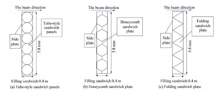
In order to design a side sandwich, panel structure, the middle section of a 70 000 DWT bulk carrier was taken as the study object. The middle section was 26.88 m long, 32.2 m wide and 18.6 m high. In the three designs for side filling type sandwich structures, the filling sandwich was distributed along the beam direction, including honeycomb sandwich plate, tube-style sandwich panel, and folding sandwich plate. These designs are shown in Fig. 1.
|
Fig.1 Side structures with filling sandwich |
Having tested whether an inter-layer could increase the side structure strength of single-hull, and having made a comparative analysis of contact force, damage, absorption energy and critical collision speed of these three filling structures, it is shown that design can greatly improve crashworthiness. The sandwich structure consists of upper and lower skins, 5.8 m high and 0.018 m thick, and an inter-layer 0.4 m high. Considering two designs for the inter-layer thickness, one ensures that three sandwich layer thicknesses are coincident with each other, and the other one adjusts the thickness of the three sandwich layers so that the mass of the sandwich layer is the same.Under the first condition, the mass increments of the three sandwich layers are different. In the analysis of energy absorption and critical collision speed, mass increment is considered as a factor, which can take into account the respective increase of crashworthiness per unit mass in the three designs. The first kind of sandwich layer design was used in the analysis. In addition, in order to make a more comprehensive comparison of the damage of the sandwich structures, the two kinds of sandwich layer designs were considered in the analysis of structural damage. Based on the comparison of the three designs, an optimal design was determined.
3 Finite Element Model of Sandwich Plate 3.1 Ship ParametersThe vertical collision of the rigid bulbous bow with amidships is the worst situation in ship-ship collision. In reality, collision occurs in the areas between the bottom plate in the ship and the main deck near the waterline plane. In this study of the different crashworthiness of different side structures, the collision area was set where the side structure had been improved. The parameters for the colliding ship and collided ship are shown in Table 1.
| Table 1 Ship parameters |
3.2 Model Parameters
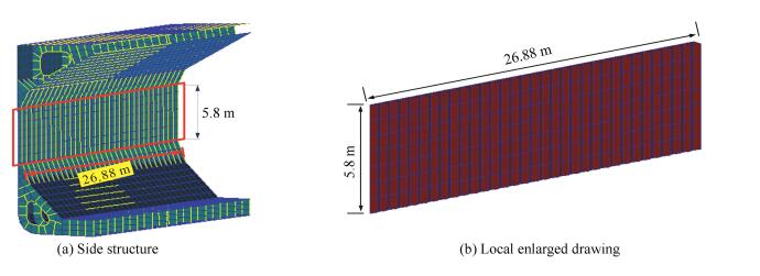
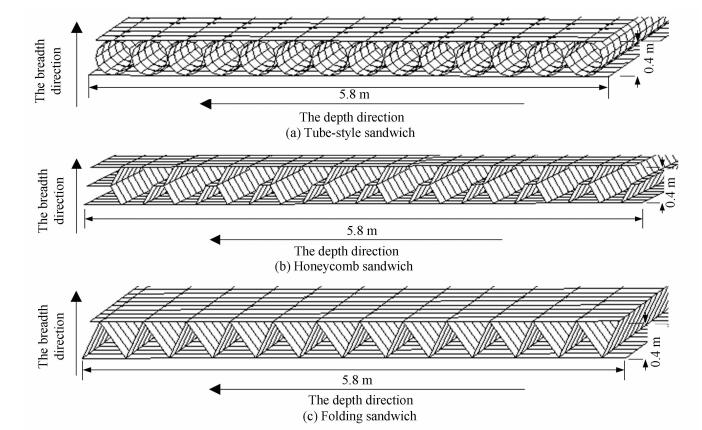
Fig. 2 shows the finite element model of the standard structure. Before improvement, the tested section mass was 795 440 kg. Based on the first design of sandwich layer, where the thickness of the three sandwich layers is the same, if the ship adopts the tube-style sandwich structure, the section mass will be 831 276 kg; if it is filled with the honeycomb sandwich layer structure, the mass will be 825 868 kg; if filled with the folding layer structure, the mass will be 826 673 kg. In the second sandwich layer design, the mass is the same, and the mass of the three sections will all be 831 276 kg. The finite element models of the improved side structures are shown in Fig. 3.
|
Fig.2 Finite element model of the standard structure |
|
Fig.3 Finite element models of the advanced filling sandwich structures |
In the simulation test, the bow of the colliding ship was set to be a rigid body, the side structure of the collided ship as deformable, the finite element models are four or three node shell elements. To simplify the analysis, the collided ship is assumed to be motionless and the colliding ship running at a speed of 15 Kn (7.8 m/s), the bow of the colliding ship collides vertically to the side structure of the collided ship. In the collision, it is assumed that motions along the length of the collided ship and of the molded depth are constrained, it can only move along the beam direction. The colliding ship moves vertically in the direction along the length of the collided ship. An adaptive master-slave surface is used in the simulation.
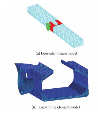
In the simulation, the hull cabin replaces the whole ship model. Given that the ship mass and moment of inertia have an influence on the calculation results, the mass of the ships must be distributed. When collision occurs, the degree of structural damage varies if it is near or far from the collision zone. The deformation is small if the structure is far from the collision zone, so the part of the model far away from the collision zone is replaced by an equivalent beam[15]. The mass of the ship apart from the cabin mass that takes part in the collision is distributed on the equivalent beam. The mass of the standard side structure ship is M0, if the mass of the middle section is m1, the mass of the equivalent beam is m2, then M0=m1+m2.
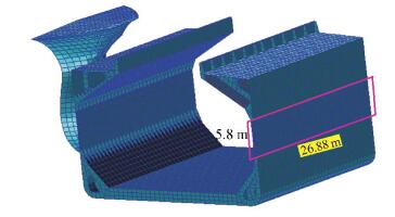
In the collision, the fluid around the ship is considered as the added mass which is added to the side structure that is not in collision zone[16], as shown in Fig. 4. The added mass is ΔM0 and the coefficient of the added mass is 0.4 based on an empirical equation[17]. Since a filling layer sandwich is added to the side structure, accordingly, the ship's mass is increased and the increased ship's mass is Δm. So, in the simulation, the total mass of the collided ship is M=M0+Δm+ΔM0, where ΔM0=0.4(M0+Δm).
|
Fig.4 The added mass area |
If based on the same thickness of sandwich layer, the mass in the three filling layer model will be different. The mass of the ship is determined by adapting the density of the middle section or the equivalent beam. The densities of all the side structures as shown in Table 2.
| Table 2 Structure densities |
We selected mild steel as the material of the ship. In order to study the integral structure damage in the collision area, plastic-kinematic material was considered in the analyses, which satisfies Cowper Symonds constitutive equation as follows:
| $ \frac{\sigma_{0}^{\prime}}{\sigma_{0}}=1+\left(\frac{\dot{\varepsilon}}{D}\right)^{\frac{1}{q}} $ | (1) |
where,
| Table 3 Plastic kinematic material properties |
3.3 Method for Solving the Finite Element
The finite element simulation used the explicit MSC.Dytran time integration method. Supposing the time step number is n, the motion equation of the explicit time integration method is as follows:
| $ \mathit{\boldsymbol{M}}{a_n} + \mathit{\boldsymbol{C}}{v_n} + \mathit{\boldsymbol{K}}{d_n} = \mathit{\boldsymbol{F}}_n^{{\rm{ext}}} $ | (2) |
where, M, C, K respectively show the structural mass matrix, damping matrix and structural stiffness matrix; an is the approximate value of the acceleration in the step n; vn is the approximate value of the speed in the step n; dn is the approximate value of the displacement in the step n; and Fnext is the external load columns array.
The motion equation is rewritten as:
| $ \mathit{\boldsymbol{M}}{a_n} = \mathit{\boldsymbol{F}}_n^{{\rm{ext}}} - \mathit{\boldsymbol{F}}_n^{{\mathop{\rm int}} } $ | (3) |
where Fnext is the external load vector, Fnint is the internal load vector, that is Fnint= Cvn+ Kdn.
Supposing Fnresidual shows the residual force vector, that is:
| $ \mathit{\boldsymbol{F}}_n^{{\rm{ residual }}} = \mathit{\boldsymbol{F}}_n^{{\rm{ext}}} - \mathit{\boldsymbol{F}}_n^{{\rm{int}}} $ | (4) |
Then the value of the acceleration is obtained as in:
| $ {a_n} = {\mathit{\boldsymbol{M}}^{ - 1}}\mathit{\boldsymbol{F}}_n^{{\rm{residual}}} $ | (5) |
Applying the nonlinear finite element code MSC/DYTRAN, numerical simulations with the collision model of the filling sandwich plate permitted a comparison of the improved side structures with the original side structure. The collision time was set to 0.8 s, the collision place was located in the improved area in the central part of the struck section side, the initial speed of collision was 15 Kn (7.7 m/s), the initial distance between the two ships was 0.175 m, the finite element model of the collision is shown in Fig. 5.
|
Fig.5 Finite element model of ship collision |
4.1 Collision Force Analysis
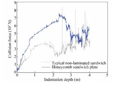
Fig. 6 shows collision forces varying with indentation depth for the honeycomb sandwich and the standard structure. The filling layer structure notably improves the crashworthiness of side structure and delayed rupture of the side structure plates, markedly reducing the damage and deformation of the side structure. The impact that the collision has on three improved structures varies little. Because there is no visible difference in the collision force for three different sandwich structures, only the results for the honeycomb sandwich structure are shown for comparison. The other two types of structures have similar changes in collision force.
|
Fig.6 Collision force versus indentation curves |
As shown in Fig. 6:
1) Collision force shows nonlinearity. During the different stages of the collision, there were many periods of loading and varying degrees of unloading. Every time when it unloads, some components or elements failed to function. Further simulation analysis showed that the collision force declines due to membrane deformation and fracturing of the side structure of the collided ship.
2) The collision force curve of the honeycomb sandwich side structure has almost the same variation trend as that of the conventional type side structure. Before the side structure plates are broken, the collision force increases as the collision depth increases, while the force declines after the plates are broken. The collision force curve of the side structure with the honeycomb sandwich shows that its fluctuated point is in hysteresis as compared with that of the conventional type side structure.
3) The curve of the honeycomb sandwich of the side structure also is higher when compared to that of the conventional type side structure, which clearly indicates that the crashworthiness of the side structure with the honeycomb sandwich is much improved. Even when the collision depth was the same, the average collision force of the side structure with the honeycomb sandwich is stronger than that of the conventional type side structure, showing the capacity of energy absorption of the side structure with the honeycomb sandwich is much greater.
4) The collision force of the side structure with the honeycomb sandwich declines because the upper and lower skins ruptured and the filling sandwich was deformed. The honeycomb sandwich side structure plates were broken when collision depth was 2.38 m, while at the depth of 1.73 m, the plates of the conventional type side structure were broken after further simulating calculation. So, the honeycomb sandwich side structure improves the crashworthiness by increasing the collision depth of side structure plates when they are broken in a collision.
4.2 Collision Structural Damage AnalysisIn order to make a more comprehensive comparison and analysis of the damage to the sandwich structures, the two kinds of sandwich layer designs were considered in the analysis of structural damage.
1) The thickness of the sandwich layer is the same.
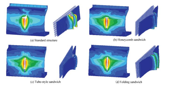
To ensure the thickness of the sandwich panel is uniform, the damage of four kinds of structure and local damage of sandwich layer under the same collision conditions, as shown in Fig. 7.
|
Fig.7 Damage deformation in different side structures (1) |
2) The mass of the sandwich layer is the same.
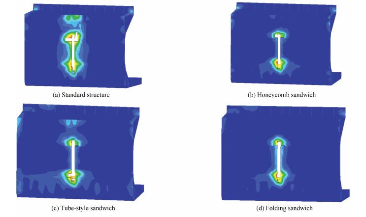
Ensuring that the mass of the sandwich layer was the same, means therefore the damage deformation to each structure under the same collision conditions was as shown in Fig. 8.
|
Fig.8 Damage deformation in different side structures (2) |
Partial collision damage occurs, and structural damage in the collision area is more serious, while the structure far away from the collision area has little damage.
Fig. 7 and Fig. 8 shows the damage deformation nephogram for the conventional type side structure and the three improved structures. As seen in the figures, the damage and deformation of the side structure concentrates in the collision contact area, specifically the structurally improved area. The damage deformation area is generally symmetrical. Each time the collision unloads, it means that some components failed to function or are broken; the elements reaching the strain failure criteria will fade, that is, failure elements are removed from the network and thus the cavity is formed in the side structure. The simulation tests demonstrate that tensile deformation occurs in the collision area, and this kind of deformation extends to the ends and increases the longitudinal pull gradually, before the shell is broken.
Compared to the conventional type of structure, the expansion of the damage deformation range of the three filling structures means the increasing capacity of energy absorption because more components take part in the collision and absorb the collision energy that causes deformation and damage. Given the partial damage and deformation in the collision area, and no matter how the sandwich layer is designed, the three structures that were exposed to similar situations had fewer failed elements. As can be seen from Fig. 7 and Fig. 8, the damage ranges of the three sandwich structures are not too different. This shows that the filling layer has alleviated the collision to a degree and reduced damage and deformation; the three structures have almost the same impacts.
Energy absorption and critical collision speed of each filling layer structure will be analyzed as follows for a comprehensive consideration of crashworthiness per unit mass. The mass increment must be considered as a factor when analyzing energy absorption and critical collision speed, so the first kind of sandwich layer design will be used in the analysis.
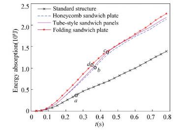
4.3 Energy Absorption AnalysisBy comparative analysis, the three filling layer structures markedly increase the capacity of the side structure to absorb collision energy. The main reason is that the filling layer structures add to the number of components that take part in the collision to absorb the collision energy in the collision. For single-hull ships, the limit state is a cracking side plate.
Simulation results show that the plate of the conventional type side structure was broken at the collision time of 0.25 s (point a in Fig. 9), when the energy absorbed is 35 177 kJ. The plate of the honeycomb sandwich side structure was broken at the collision time of 0.37 s (point b). The energy absorbed was up to 102 827 kJ; the plate of the tube-style sandwich side was broken at 0.44 s (point c), when the energy absorbed is 136 825 kJ. The folding sandwich plate was broken at 0.35 s (point d) and the absorption energy was 107 734 kJ. The capacity of the three improved structures to absorb energy has increased dramatically. In terms of energy absorption when the plates of side structure are broken, the tube-style sandwich layer structure has the strongest capacity among the three structures. In simulation calculations, the plate of the standard structure was broken at the collision depth of 1.73 m. The honeycomb sandwich, side structure plate was broken at 2.38 m. The collision depth for tube-style sandwich structure when its plate was broken was 2.88 m, and the folding filling layer, structure plate was broken at 2.30 m. Thus, the three improved structures defer the plates from breakage and the tube-style sandwich side structure showed the best result.
|
Fig.9 Energy absorption curves |
It is not enough to judge the crashworthiness of the three improved structures based on their collision depth and capacity to absorb energy, the crashworthiness index supports a further analysis. Crashworthiness index refers to the energy that unit structure weight absorbs under a certain extreme condition. Table 4 shows the ratio of the mass increment and energy absorption increment for the three improved side structures, reflecting a comparison between the improved structures and the conventional type of side structure using the crashworthiness index. The energy absorption in the table specifically refers to the ultimate deformation energy when the side plate is broken. Although the improved structure increases the weight of the ship body, given the total mass of the ship, the mass increment ratio is irrelevant when compared to the increment ratio for energy absorption.
| Table 4 Comparison of structural crashworthiness |
Table 4 shows that the crashworthiness indexes of the improved structures dramatically increased in comparison with the conventional type of side structure. The index for the side structure with the honeycomb sandwich increased 182%, when taking a side plate fracture as a critical condition. The index for the tube-style sandwich structure increased by 272%; and the index for the folding sandwich structure increased by 195%. Compared to the energy absorption increment, the mass increment of the three structures was small; however, this value is only the ratio relevant to the weight of the side structure in the stimulation calculations. Given the total ship mass, the mass increment ratio can be ignored in contrast to the energy absorption increment ratio.
The improved structures strengthen the side structures capacity to absorb energy, improving collision depth level, its capacity to absorb energy and the crashworthiness index. The side structure with the tube-style sandwich layer was determined to be the best among the three improved structures, after a comprehensive comparison.
4.4 Critical Collision SpeedThe critical collision speed determines the level of crashworthiness of a ship, and is widely used in engineering. The critical speed computational formula [21] from Germanischer Lloyd's rules for construction and classification of ships is used to calculate the critical collision speed of four side structures, thereby determining the side structure that has the highest crashworthiness level.
| $ V_{c r}=2.75 \sqrt{\frac{E_{c r}}{m_{2}}\left[1+\frac{m_{2}}{m_{1}}\right]} $ | (6) |
where, Ecr is the ultimate deformation energy, kJ; m1 is the mass of the colliding ship, including the 10% added mass, t; m2 is the mass of the collided ship, including the 40% added mass, t; Vcr is the critical collision speed, Kn. The calculation results are shown in Table 5.
| Table 5 Comparison of critical collision speeds |
Table 5 shows that the critical collision speeds of the improved structures are all higher than the conventional type of side structure, which indicates that the level of crashworthiness for the improved structures has dramatically increased. The tube-style sandwich structure in particular, had the biggest critical collision speed, meaning it has the highest level of crashworthiness. Consequently, in terms of the crashworthiness, the tube-style sandwich structure was the best among the three improved structures.
5 ConclusionsThis paper focuses on the impact that the filling layer structures have on the crashworthiness of the ship based on the finite element numerical simulations. Single hull sandwich plates were designed to include honeycomb sandwich plates, tube-style sandwich panels, and folding sandwich plates. Ship parameters, model parameters and a method to solve the finite element were introduced. The collision force, the damage deformation, the critical collision speed as well as the energy absorption of the improved sandwich layer side structures were compared with the conventional type of side structure by applying the nonlinear finite element process MSC/Dytran to conduct the numerical simulations, and some general conclusions can be drawn.
Our research indicates that a filling layer side structure can increase crashworthiness, which provides a reference for ship design improvements in areas where the structure is susceptible to damage. Filling layer side structures can increase the crashworthiness of the ship without reducing overall longitudinal strength. When the filling layers are of equal thickness or mass, the damage ranges of the three sandwich structures are not too different. After a comprehensive comparison, aside structure with a tube-style sandwich layer was found to be the best among the three improved structures. The outcome of this study provides a reference for the crashworthiness assessment of the side structures and crashworthiness design optimization for new side structures.
In the future research, we can make further research on structure optimization of the new type side structures considering the mass increment of the ship. Further research will help improve the crashworthiness of ships as well as control the mass increment of ships.
| [1] |
Chen C. A review of research on ship collision. Water Resources & Hydropower of Northeast China, 2016(4): 67-70. DOI:10.14124/j.cnki.dbslsd22-1097.2016.04.026 (  0) 0) |
| [2] |
Lyu D. The Research of Damage to Ship Collision Region and Application. Dalian: Dalian Maritime University, 2012.
(  0) 0) |
| [3] |
Wang Zili, Zhang Yanchang. Single hull ship structure crashworthy design based on sandwich panel. Shipbuilding of China, 2008, 49(1): 60-65. DOI:10.3969/j.issn.1000-4882.2008.01.009 (  0) 0) |
| [4] |
Zhang Yanchang, Wang Zili, Zhang Shilian. Simulation analysis of folded core structure under dynamic load. Journal of Ship Mechanics, 2010, 14(1): 114-120. DOI:10.3969/j.issn.1007-7294.2010.01.015 (  0) 0) |
| [5] |
Zhang Yanchang, Wang Zili. Study on crashworthiness of honeycomb sandwich panel under lateral dynamic load. Journal of Jiangsu University of Science and Technology (Natural Science Edition), 2007, 21(3): 1-5. DOI:10.3969/j.issn.1673-4807.2007.03.001 (  0) 0) |
| [6] |
Kang J M, Kim J Y, Lee K J, et al. Effect of design variables on the behavior of VLCC structure in collision. Proceedings of the 13th MSC Users Conference, 1996, 1-12. (  0) 0) |
| [7] |
Brown A, Tikka K, Daidola J C, et al. Structural design and response in collision and grounding. SNAME Transactions, 2000, 108: 447-473. (  0) 0) |
| [8] |
Naar H, Kujala P, Simonsen B C, et al. Comparison of the crashworthiness of various bottom and side structure. Marine Structure, 2002, 15(4-5): 443-460. DOI:10.1016/S0951-8339(02)00012-6 (  0) 0) |
| [9] |
Paik J K. Innovative structural designs of tankers against ship collisions and grounding: A recent state-of-the-art review. Marine Technology, 2003, 40(1): 25-33. (  0) 0) |
| [10] |
Michel K, Winslow T S. Cargo ship bunker tankers: Designing to mitigate oil spillage. Marine Technology, 2000, 37(4): 191-199. (  0) 0) |
| [11] |
Mita S, Yamashita K, Nonomura C. On the characteristic of the new material fender for ship collision. Transactions of the Japan Society of Mechanical Engineers Series A, 2004, 70(5): 703-709. DOI:10.1299/kikaia.70.703 (  0) 0) |
| [12] |
Kujala P, Klanac A. Steel sandwich panels in marine applications. Brodogradnja, 2005, 56(4): 305-314. (  0) 0) |
| [13] |
Ozguc O, Das P K, Baltrop N, et al. Numerical modeling of ship collision based on finite element codes. Proceedings of the 3rd International ASRANet Colloquium. Glasgow, UK, 2006.
(  0) 0) |
| [14] |
Zhao Xiaobo. Research on Finite Element Simulation of Ship-ship Collision. Wuhan: Wuhan University of Technology, 2016.
(  0) 0) |
| [15] |
Wang Zili, Gu Yongning. A simplified model of numerical simulation of ship collisions. Journal of East China Shipbuilding Institute, 2001, 15(6): l-6. DOI:10.3969/j.issn.1673-4807.2001.06.001 (  0) 0) |
| [16] |
Pill I, Tabri K. Finite element simulations of ship collisions: A coupled approach to external dynamics and inner mechanics. Ships and Offshore Structures, 2011, 6(1-2): 59-66. DOI:10.1080/17445302.2010.509585 (  0) 0) |
| [17] |
Minorsky V U. An Analysis of Ship Collisions with Reference to Protection of Nuclear Power Plants. New York: Sharp (George G.) Inc., 1958.
(  0) 0) |
| [18] |
Zhou Hong, Zhang Yanchang, Yue Yalin, et al. Numerical simulation analysis technology for sandwich plate system crashworthiness. Computer Aided Engineering, 2013, 22(2): 66-71. DOI:10.3969/j.issn.1006-0871.2013.02.014 (  0) 0) |
| [19] |
Servis D, Samuelides M, Louka T, et al. Implementation of finite-element codes for the simulation of ship-ship collisions. Journal of Ship Research, 2002, 46(4): 239-247. (  0) 0) |
| [20] |
Zhang Shaoxiong, Sun Kang, Yu Zhikai, et al. Collision simulation and research of double-hull oil ship of the three gorges reservoir area. Ship & Ocean Engineering, 2009, 38(3): 8-10. DOI:10.3963/j.issn.1671-7953.2009.03.003 (  0) 0) |
| [21] |
Germanischer Lloyd. Rules for Classification and Construction. Section 33.Hafen City, 1998.
(  0) 0) |
 2019, Vol. 26


