The performance of bogies working as running gears of rolling stocks plays a key role in the ride quality of vehicles[1-3]. The rotation resistance coefficient of bogies as an important parameter has direct impact on the dynamic performance of vehicles[4]. If the rotation resistance coefficient is excessively big, the ability of curve negotiation is weakened, and if it is excessively small, the transverse stability is adversely influenced[5]. Therefore studies on the rotation resistance coefficient of bogies are necessary for new products development and bogie performance optimization. Results of rotation resistance tests can be applied to design the moment of derailment resistance, reflect the entire wear levels of wheel and rail, and serve as a certification course for dynamic model of vehicles performance simulation[6-8].
The rotation resistance tests on bogies are the key items of type tests on vehicles, which were only performed by theoretical calculation in the past due to restrained test conditions, making it hard to obtain accurate rotation resistance coefficient with bogies connected with car body. Type A vehicle motor bogies were selected as research objects in this study. Theoretical analysis and dynamics calculation were conducted with certain pertinence, and systematic research-orientated tests were performed based on the theoretical researches by means of a test bench with newly created bogie parameters. The changing trend of the parameter was investigated through the researches on the rotation resistance coefficient under various operating conditions with different bogie status at different rotatory speeds, which was used to examine its impacts on the dynamic behaviors of vehicles.
2 Theoretical Calculation of Rotation Resistance Coefficient 2.1 Reference StandardsEN14363 Railway application-Ride quality of rolling stocks-Running performance test and static test[9] define the test principle of rotation resistance for the sake of derailment safety. The measurement of rotation resistance coefficient was considered with the conditions such as empty loaded, fully loaded, over-inflated and inflated, and over-deflated air springs at different rotatory speeds, angles, and so forth. The tests were performed to obtain the result of the rotation resistance coefficient[10].
The rotation resistance coefficient of bogies, X-factor, can be found with the formula below:
| $ X-\text { factor }=\frac{T}{2 Q \times 2 a} $ | (1) |
where X-factor denotes the rotation resistance coefficient of bogies; T (kN·m) is the moment of rotation resistance of bogies; 2Q (kN) is the average axle load of rotating bogie; and 2a (m) is the wheelbase of bogie.
As specified in the standard EN14363, the rotation resistance coefficient for railway passenger, mail vehicles, or locomotives should be X ≤ 0.1.
2.2 Theoretical CalculationEq. (1) is used to calculate the rotation resistance coefficient with inflated and deflated air springs.
For over-inflated and inflated air springs, the moment of rotation resistance of bogies T is calculated as
| $ T=2 K s x \times A \times d_{s}^{2} $ | (2) |
where Ksx (MN/m) denotes the horizontal static stiffness of air spring; A (rad) is the maximum rotation angle; and ds(m) is half of transverse distance over two air springs on one bogie.
For over-deflated air springs, the moment of rotation resistance of bogies T can be expressed as
| $ T=2 m \times W \times d_{s} $ | (3) |
where m denotes the frictional factor of air spring wear plate, and W(kN) is the vertical load of air springs.
Maximum rotation angle: A=3.5°=0.061 rad;
Air spring horizontal static stiffness: Ksx =0.12 MN/m;
Transverse distance of two air springs on one bogie: ds=1.9 m;
Frictional factor of air spring wear plate m takes 0.05;
Average axle load of bogie measured on tangent and level track: 2Q=156.602 kN;
Wheelbase of bogie:2a =2.5 m.
Following values were obtained through calculation:
Rotation resistance coefficient with inflated air springs: X-factor=0.033 7;
Rotation resistance coefficient with deflated air springs: X-factor=0.019 9.
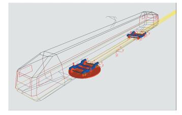
3 Dynamics Calculation 3.1 Dynamics ModelThe bogie parameters tests were simulated on a test bench and the zero-freedom articulation restrains were applied via wheel-set and rotating table. With the simulated bogie secured on the test bench, a rotatory torque was applied to the rotating table as a rotation resistance moment acted on the bogie. The size and the angle of the rotating resistance torque could thus be obtained. The whole vehicle system of type A vehicle is comprised of seven stiff bodies including car body, two bogie frames, and four axle boxes. The whole vehicle model was used in the calculation of anti-yaw, lateral and vertical operational stability of the vehicle, and curve negotiation. The car body took five freedoms: lateral, vertical, side roll, nodding, and shaking. Bogie frames took six freedoms: longitudinal, lateral, vertical, side roll, nodding, and shaking. The wheel-set took three freedoms: longitudinal, lateral, and shaking. The movements of the rotating table were coupled with that of wheel-sets, vertically and laterally. The simulation model is shown in Fig. 1.
|
Fig.1 Simulation model for tests |
3.2 Impacts of Rotation Angle on Factors
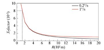
Impacts of rotation angle on rotation resistance torque with inflated air springs were calculated through simulation. Fig. 2 shows the relationship among rotation resistance coefficient, rotation speeds, and curve radii. The calculation was made with the curve radii from 100 m to 2000 m, spaced by 50 m, at 0.2°/s and 1°/s rotation speeds respectively. Results show that the rotation resistance coefficient strongly correlated with the curve radii during curve negotiation by vehicle. The rotation resistance coefficient changed significantly as the curve radii varied within a range of 100 m-600 m, and smoothly as the curve radius exceeded 1000 m.
|
Fig.2 Relationship among rotation resistance coefficient, curve radii and rotation speeds |
3.3 Impacts of Horizontal Stiffness of Air Spring on Factors
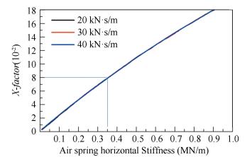
In this paper, the relationships between rotation resistance coefficient and horizontal stiffness of air springs at different rotation speeds and curve radii are obtained. Fig. 3 shows the impact of different air spring stiffness on rotation resistance coefficient at 0.2 °/s and at curve radius of 300 m during curve negotiation. Results were similar at other curve radii, indicating that the rotation resistance coefficient and the horizontal stiffness of air springs have a positive correlation.
|
Fig.3 Relationship between rotation resistance coefficient and air spring horizontal stiffness |
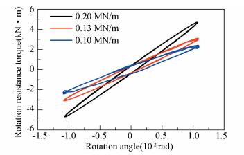
Fig. 4 presents the relationship between rotation resistance torques and rotation angles (at 0.2 °/s) at curve radius of R=700 m under different air spring horizontal stiffness. It can be concluded that the rotation resistance coefficient is mainly influenced by air spring stiffness and rotation angles (negotiated curve radii), and the greater the rotation angle is, the greater the rotation resistance coefficient is.
|
Fig.4 Relationship between rotation resistance torque and rotation angles |
4 Test 4.1 Preparation of Test
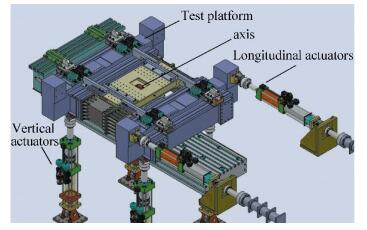
The measurement of rotation resistance coefficient of type A vehicle motor bogies was performed on the bogie parameters test bench of the Railway Vehicles Laboratory. The test bench was connected with two lateral beams at its bottom by lower transom multiple-segmented longitudinal beams, center plate, and transition guide rail of lower transom for the measurement of rotating torque acted on bogie[11-13]. As shown in Fig. 5, the table can turn about a fixed shaft, while the lateral movement of the table is restrained, which is vertically supported by four vertical actuators and lengthwise supported by two longitudinal actuators. The vibration of the bogie table can be achieved with the aid of the stretch and extract movement of the two longitudinal actuators[14].
|
Fig.5 Testing table for measurement of rotation resistance |
The two vertical actuators are spaced longitudinally to 2.5 m and the longitudinal actuators are spaced to 3.4 m. The testing table was installed with rail transition jigs and fixtures, and the top surface of the rail transition jig was flushed with top of rail at entrance into the laboratory at the same reference. Fig. 6 shows the picture of the testing table[15-17].

|
Fig.6 Testing table for measurement of rotation resistance |
4.2 Test Procedure
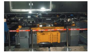
As the vehicle under test was pushed to the specified position on the testing table for the measurement of rotation resistance, the four wheels at End A of the vehicle were secured with wheel stopper and fixtures to prevent relative displacement of these wheels to the testing table, and the bogie at End B of the vehicle was free. Fig. 7 displays the picture of the secured wheels.
|
Fig.7 Picture of secured wheels |
The testing table enables the table to turn about the rotating shaft by controlling the stretch and extract of the two longitudinal actuators. The four vertical actuators were used for displacement compensation to prevent the table from vertical displacement during the rotation. The resistance and displacement generated during the rotation of bogie were measured by a 3D force-measuring table and a laser displacement sensor, and were converted to the relationship between rotating torque and angle, where the assessment of the vehicle was thus made. During the test, the table turned at constant angular speeds and the signals of the displacement control of the two actuators were ladder-shaped waves with phase difference of 180 degrees.
The supporting capability of air springs can be measured before and after formal tests. It is required that the car body under test has no apparent deflection within the time needed for the test (deflection no greater than 5 mm in 12 hours). In addition, it is necessary to check the height of car body floor above the top of rail before and after the whole test to ensure no obvious leakage at air springs during the test. The tests were deemed invalid in case of vehicle deflection over 5 mm.
4.3 Cases of TestThe maximum rotation angle of bogie is ±3.5° with vehicle status at empty load, and the operating conditions for comparison were set, as shown in Table 1.
| Table 1 Operating cases for test |
4.4 Test Results
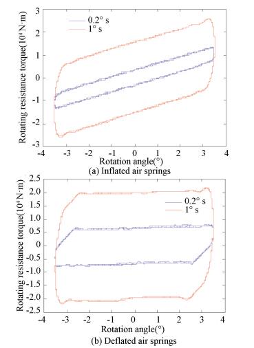
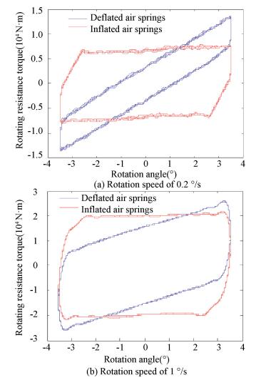
The relationship between rotation angle and rotation resistance torque of motorized bogies are shown in Figs. 8-11.
|
Fig.8 Relationship between rotation resistance torque and rotation angle |
|
Fig.9 Relationship between rotation resistance torque and rotation angle |

|
Fig.10 Relationship between rotation resistance torque and rotation angle |
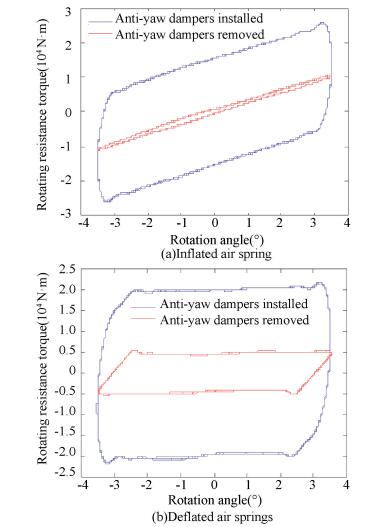
|
Fig.11 Relationship between rotation resistance torque and rotation angle |
(1) Motor vehicle at empty load with anti-yaw dampers installed.
(2) Motor vehicle at empty load with anti-yaw dampers installed.
(3) Motor vehicle at empty load with rotation speed of 0.2 °/s.
(4) Motor vehicle at empty load with rotation speed of 1°/s.
As shown in Tables 2-5, the rotation resistance coefficients of bogies obtained from theoretical calculation for the type A vehicles at inflated and deflated air springs were 0.033 7 and 0.019 9, respectively. Test result shows that at rotation speed of 0.2 °/s, inflated and deflated air springs were 0.034 9 and 0.020 1 with anti-yaw dampers installed, which was quite close to that of the theoretical calculation, i.e. 0.026 8 and 0.011 0 with anti-yaw dampers removed. At rotation speed of 1 °/s, inflated and deflated air springs were 0.066 0 and 0.055 7 with anti-yaw dampers installed, and 0.027 4 and 0.014 0 with anti-yaw dampers removed
| Table 2 Results of test performed at rotation speed of 0.2 °/s (with anti-yaw dampers installed) |
| Table 3 Results of test performed at rotation speed of 0.2 °/s (with anti-yaw dampers removed) |
| Table 4 Results of test performed at rotation speed of 1°/s (with anti-yaw dampers installed)) |
| Table 5 Results of test performed at rotation speed of 1°/s (with anti-yaw dampers removed) |
Judgment can be made on the basis of the standard EN14363 that the maximum value of the above rotation resistance coefficient obtained from the tests was 0.066 0 (less than 0.1) when the case was at empty load. For normally inflated air springs, at rotation speed of 1 °/s, those in other cases were all less than 0.1, which means that the rotation resistance coefficient of bogies of motor vehicle meets the design requirement.
5 ConclusionsThe rotation resistance coefficients of bogies obtained from the test were less than 0.1, which is in conformity with the standard EN14363. The test result and the theoretical calculation have corresponding curvilinear trend. Factors of the rotation resistance coefficient are analysed below.
The result of dynamic calculation shows that the rotation resistance coefficient strongly relates to curve radii during curve negotiating. The factor significantly varied as curve radius changed from 100 m to 600 m, smoothly at curve radius over 1000 m, and the greater the rotation angle is, the greater the factor is. The factor varies proportionally with air spring horizontal stiffness.
The rotation resistance torque of motorized bogies increases with the increase of the rotation angle. The rotation resistance coefficient with normally inflated air springs is much greater than that obtained with deflated air springs. The test results also show that the rotation resistance coefficient increases as the rotation speed goes up.
Under the test conditions, i.e., at empty load, at the same rotation speed, and with the same status of air springs inflated or deflated, the rotation resistance coefficient with anti-yaw dampers installed is greater than that with anti-yaw dampers removed. It is known from the test that the anti-yaw damper increases the rotation resistance torque of bogie during the test for rotation resistance, and the greater the rotation speed is, the greater the rotation resistance torque is.
| [1] |
Tokuda N, Okamoto I, Fujita T, et al. Development of gauge change bogies. Qr of Rtri, 2003, 44(3): 109-113. DOI:10.2219/rtriqr.44.109 (  0) 0) |
| [2] |
Zhang J, Li J J, Tian H Q, et al. Impact of ground and wheel boundary conditions on numerical simulation of the high-speed train aerodynamic performance. Journal of Fluids & Structures, 2016, 61(4): 249-261. DOI:10.1016/j.jfluidstructs.2015.10.006 (  0) 0) |
| [3] |
Han P, Zhang W H, Li Y. Wear characteristics and prediction of wheel profiles in high-speed trains. Journal of Central South University, 2015, 22(8): 3232-3238. DOI:10.1007/s11771-015-2861-7 (  0) 0) |
| [4] |
Huang Youmin, Wang Tsungshou. Rotational resistance behavior and field testing of two-axle bogie design. Vehicle System Dynamics, 1999, 31(1): 47-63. DOI:10.1076/vesd.31.1.47.2098 (  0) 0) |
| [5] |
Ghazavi M R, Taki M. Dynamic simulations of the freight three-piece bogie motion in curve. Vehicle System Dynamics, 2008, 46(10): 955-973. DOI:10.1080/00423110701730737 (  0) 0) |
| [6] |
Tanaka T, Iida K, Suzuki M, et al. Evaluation of rotational resistance of bogies. Proceedings of the Institution of Mechanical Engineers Part F: Journal of Rail & Rapid Transit, 2017, 231(5): 535-545. DOI:10.1177/0954409716668209 (  0) 0) |
| [7] |
Huang Y M, Wang T S. Running stability simulation and field testing of two-axle bogie design. International Journal of Vehicle Design, 2001, 26(2/3): 131-145. DOI:10.1504/IJVD.2001.001934 (  0) 0) |
| [8] |
Shi H L, Wu P B, Luo R, et al. Calculation and laboratory testing of the rotation resistance of a bogie. Proceedings of the Institution of Mechanical Engineers Part F:Journal of Rail & Rapid Transit, 2015, 229(2): 210-219. DOI:10.1177/0954409713508110 (  0) 0) |
| [9] |
British Standards Institution. Bs-En-14363: 2016. Railway Applications. Testing and Simulation for the Acceptance of Running Characteristics of Railway Vehicles. Running Behaviour and Stationary Tests. London: BSI, 2016.
(  0) 0) |
| [10] |
Li S J, Gao H B, Deng Z Q. Mobility performance evaluation of lunar rover and optimization of rocker-bogie suspension parameters. Proceedings of the 2nd International Symposium on Systems & Control in Aerospace & Astronautics ISSCAA. Piscataway: IEEE, 2008. 1 - 6. DOI: 10.1109/ISSCAA.2008.4776154.
(  0) 0) |
| [11] |
Zhao D X, Xu M, Liu P, et al. Research on hybrid hydraulic excavator test bench. Applied Mechanics & Materials, 2011, 121-126: 3456-3460. DOI:10.4028/www.scientific.net/AMM.121-126.3456 (  0) 0) |
| [12] |
Lan Z K, Su J, Xu G, et al. Study on dynamical simulation of railway vehicle bogie parameters test-bench electro-hydraulic servo system. Physics Procedia, 2012, 33: 1663-1669. DOI:10.1016/j.phpro.2012.05.268 (  0) 0) |
| [13] |
Wang X Y, Liang S L, Li W X, et al. High speed train bogie wheel-rail relative vibration with bench reconstruction technology. Proceedings of the 1st International workshop on High-Speed and Intercity Railuays.Berlin: Springer, 2012, 147: 39-49. DOI: 10.1007/978-3-642-27960-7_4.
(  0) 0) |
| [14] |
Yan J M, Wang K W, Dai H Y, et al. A study of the high speed passenger bogie utilizing the full scale roller testing rig. Vehicle System Dynamics: International Journal of Vehicle Mechanics and Mobility, 2008, 23(Sup1): 554-565. DOI:10.1080/00423119308969540 (  0) 0) |
| [15] |
Shi H L, Song Y, Wu P B, et al. Calculation and testing of suspension stiffness of a bogie of high speed EMU. Journal of Jilin University (Engineering and Technology Edition), 2015, 45(3): 776-782. DOI:10.13229/j.cnki.jdxbgxb201503014 (  0) 0) |
| [16] |
Matsumoto A, Sato Y, Ohno H, et al. Curving performance evaluation for active-bogie-steering bogie with multibody dynamics simulation and experiment on test stand. Vehicle System Dynamics: International Journal of Vehicle Mechanics and Mobility, 2008, 46(Sup1): 191-199. DOI:10.1080/00423110801935806 (  0) 0) |
| [17] |
Zhang D L, Su J, Gong H B, et al. Design and research of bogie parameters determination test bench for high-speed train. 2011 International Conference on Remote Sensing, Environment and Transportation Engineering. Piscataway: IEEE, 2011.210-213. DOI: 10.1109/RSETE.2011.5964252.
(  0) 0) |
 2019, Vol. 26


