Water entry is generally considered important in naval architecture, ocean engineering and costal engineering. However, it is equally important in aerospace engineering. One classic example in aerospace engineering is helicopter ditching, which is a coupling process of the fluid and the body movement. Fluid exerts a great slamming force on helicopter and changes its motion. Meanwhile, helicopter significantly changes the boundary conditions of flow field. How a helicopter ditches, namely, its way of water entry, is of great concern because it influences the force on helicopter and is essential in terms of structural design and safety.
Acknowledging that the way of water entry is important to helicopter ditching, the way a 2D V-buoy enters into water is used as the research object in this paper. Extensive researches including experimental studies and numerical simulations have been carried out to solve the problems of helicopter's and wedge's water entry. In particular, some key problems concerning helicopter's ditching in emergency were studied[1]. Li et al.[2] studied the scaled model test of helicopter ditching and their main concerns were on load test methods. The authors in Refs.[3-4] estimated the impact loads of a ditching helicopter with a V-shape bottom and a flat bottom respectively, by using the empirical formula. Helicopter's impact on calm water was simulated[5] based on the SPH-FEM method. The inflation of the emergent airbag and the ditching process of helicopter were studied[6] by using software ANSYS/LS-DYNA. Zhang et al.[7] studied the water entry of a wedge by using model test and numerical simulation. The PIV techniques were used in the model tests and the VOF method was adopted in numerical simulation. More studies on water entry of a body can be referred to reviews by Wu and Xu [8-12].
In the paper, different ways of water entry of a 2D helicopter V-buoy was simulated and its effects on the impact loads were analyzed. Specifically, the water entry of a 2D V-buoy in free fall motion and forced fall motion at a constant velocity was calculated numerically by using the software FLUENT and VOF technique. The velocity, acceleration and slamming force were calculated and compared with the results by Wu[9]. Based on the validation of the numerical model, the influence of the way of water entry on slamming force F, slamming pressure and pressure coefficient Cp were discussed.
2 Numerical Simulation Methods 2.1 Fluent Software Basic EquationsFluent software basic equations include continuity equation, N-S equation and energy conservation equation. In this paper, energy transformation is not involved, so energy conservation equation does not need to be solved.
Continuity equation:
| $ \frac{{\partial \rho }}{{\partial t}} + \frac{{\partial (\rho u)}}{{\partial x}} + \frac{{\partial (\rho v)}}{{\partial y}} + \frac{{\partial \rho }}{{\partial t}}\frac{{\partial (\rho w)}}{{\partial z}} $ | (1) |
Navier-Stokes equations with constant viscous coefficient:
| $ \left\{ {\begin{array}{*{20}{c}} {\frac{{\partial u}}{{\partial t}} + u\frac{{\partial u}}{{\partial x}} + v\frac{{\partial u}}{{\partial y}} + w\frac{{\partial u}}{{\partial z}} = {f_x} - \frac{1}{\rho }\frac{{\partial p}}{{\partial x}} + }\\ {\mu \left( {\frac{{{\partial ^2}u}}{{\partial {x^2}}} + \frac{{{\partial ^2}u}}{{\partial {y^2}}} + \frac{{{\partial ^2}u}}{{\partial {z^2}}}} \right)}\\ \begin{array}{l} \frac{{\partial v}}{{\partial t}} + u\frac{{\partial v}}{{\partial x}} + v\frac{{\partial v}}{{\partial y}} + w\frac{{\partial v}}{{\partial z}} = {f_y} - \frac{1}{\rho }\frac{{\partial p}}{{\partial y}} + \\ \begin{array}{*{20}{c}} {\mu \left( {\frac{{{\partial ^2}v}}{{\partial {x^2}}} + \frac{{{\partial ^2}v}}{{\partial {y^2}}} + \frac{{{\partial ^2}v}}{{\partial {z^2}}}} \right)}\\ {\frac{{\partial w}}{{\partial t}} + u\frac{{\partial w}}{{\partial x}} + v\frac{{\partial w}}{{\partial y}} + w\frac{{\partial w}}{{\partial z}} = {f_z} - \frac{1}{\rho }\frac{{\partial p}}{{\partial z}} + }\\ {\mu \left( {\frac{{{\partial ^2}w}}{{\partial {x^2}}} + \frac{{{\partial ^2}w}}{{\partial {y^2}}} + \frac{{{\partial ^2}w}}{{\partial {z^2}}}} \right)} \end{array} \end{array}\\ \end{array}} \right. $ | (2) |
where u, v, w are the components of velocity in the x, y, z directions respectively; fx, fy, fz are the components of the volume force in the x, y, z direction respectively; p is the pressure; ρ is the density and μ is the kinetic viscosity coefficient of the fluid.
2.2 Treatment Methods of Free SurfaceThe VOF technique is a numerical method used for constructing and capturing the free surface in computational fluid dynamics (CFD). It can deal with steady and transient problems of air-fluid interface. The basic principle of VOF is used to determine the free surface and track fluid changes by studying the fraction function S. If S=1, it means that the grid unit is occupied by the specified phase fluid. If S=0, it means that the grid unit has no specified phase fluid. If 0 < S < l, it means that the grid unit is called interphasal interface. S function can be expressed as follows[13]:
| $ \frac{{\partial S}}{{\partial t}} + u\frac{{\partial S}}{{\partial x}} + v\frac{{\partial S}}{{\partial y}} + w\frac{{\partial S}}{{\partial z}} = 0 $ | (3) |
The velocity of V-buoy when entering water can be calculated as follows:
| $v = {v_0} + \frac{{F - mg}}{m}\Delta t $ | (4) |
where v0 is the speed of 2D V-buoy in the last time-step, F is the force on 2D V-buoy, m is the mass of V-buoy, and Δt is the time-step.
2.4 Slamming CoefficientTo make it general, it is usually necessary to describe the hydrodynamic parameters in dimensionless during the slamming of V-buoy[14]. Three dimensionless parameters are adopted in this paper, including the dimensionless water depth y', the pressure coefficient CP and the slamming parameter F'.
| $ {y^\prime } = \frac{y}{{\int V (t){\rm{d}}t}} $ | (5) |
| $ {C_p} = \frac{p}{{\frac{1}{2}\rho {{(V(t))}^2}}} $ | (6) |
| $ {F^\prime } = \frac{F}{{\rho {V^3}(t)t}} $ | (7) |
where ρ is density; V(t) is velocity of the body which varies in free fall motion; t is time; p is pressure; y is submergence depth, which is the height of the intersection point between body and free surface over the bottom point of the V-buoy; F is the slamming force on V-buoy. The meaning of each parameter is shown in Fig. 1.
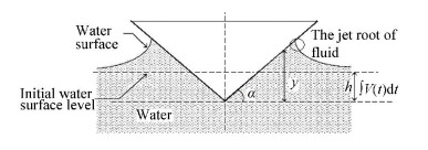
|
Fig.1 Parameters involved in describing water impact |
3 Numerical Simulation 3.1 Numerical Model and Calculation Domain
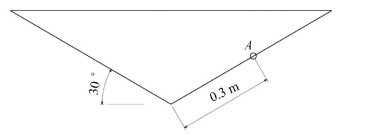
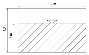
2D V-buoy with deadrise angle 30°and mass 100 kg is selected as the body. The measuring point A is located at the surface of the 2D V-buoy and the distance between point A and the bottom point of the V-buoy is 0.3 m, as shown in Fig. 2. The size of the calculation domain is 7 m×4.5 m and the water depth is 3 m, as shown in Fig. 3. In order to save compute time, the buoy is located at free water surface. The initial velocity of the body entering water is -5 m/s, which changes in free fall motion but is kept constant for forced fall motion. The coordinates O-xy is shown in Fig. 3 and the origin O is located at the bottom point of the V-buoy which lies on the calm water surface initially.
|
Fig.2 Model of the 2D V-buoy |
|
Fig.3 Computational domain |
3.2 Mesh and Boundary Conditions
Meshing is the most important step in numerical modeling. The quality of mesh can affect the accuracy of results and solution time. The dynamic meshing technology is adopted here to prevent the surrounding meshes of the body from stretching when V-buoy falls. The dynamic mesh updating method used in this paper is Dynamic Layering Method.
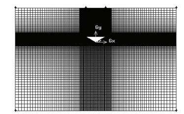
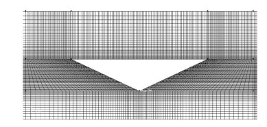
The calculation domain is divided into three parts: the upper, middle and lower parts. The middle part is the moving domain near the body, which is also defined as the independent flow domain, and has the same falling speed with the body, so as to ensure the quality of the grids around the falling body is unchanged and guarantee the computational accuracy. All the three parts are discredited in structured grids, which can greatly reduce the number of meshes and solution time. The grid of the middle part has a greater density than those of the other parts, so that accuracy can be enhanced. The mesh is shown in Fig. 4 and Fig. 5.
|
Fig.4 Meshes of the flow field |
|
Fig.5 Meshes around the 2D V-buoy |
The boundary condition of the 2D V-buoy and the bottom surface are rigid wall surfaces. The boundary condition of the top surface of the calculation domain is pressure-outlet. The boundary condition of left and right faces of the calculation domain are symmetric boundary condition.
3.3 Influence of MeshThe number of meshes is crucial for calculating precision and calculating time. This paper adopts three kinds of meshes to study their effect. Table 1 shows the influence of different numbers of grids.
| Table 1 Influence of mesh |
By calculation, when the number of grids remains around 49086, the calculated value of Fmax coincides well with the theoretical value and the error is within 5%. So in the subsequent calculation, the number of grids remains around 49086.
3.4 Numerical Simulation ResultsThe water entry of a V-buoy in either free fall or forced fall motion is calculated based on FLUENT together with UDF program and standard k-ε turbulence model, and the free surface is tracked with VOF method. For the specific numerical procedure, it is described in Ref.[15].
For water entry of a V-buoy in free fall motion, the numerical simulation was calculated over 750 time steps. The size of time-step was 0.0001 s and each time step iterated 50 times. The simulation cost 74 min by using 4-AMD opteron 2350 processors.
For forced fall motion at a constant velocity, the numerical simulation was calculated over 600 time steps. The size of a time-step was 0.0001 s and each time step iterated 50 times. The simulation cost 41 min by using 4-AMD opteron 2350 processors.
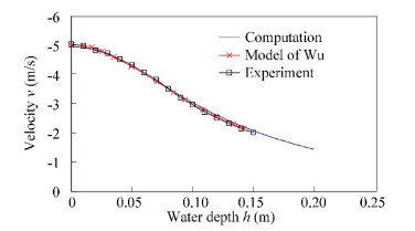
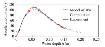
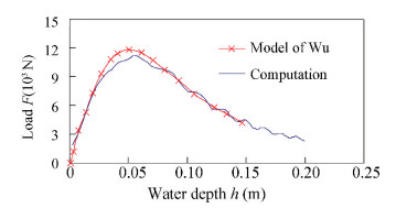
Figs. 6-8 show the variation of velocity, acceleration and fluid force of the body in free fall motion together with water depth respectively. As can be seen from Fig. 6, the calculated velocities in this paper is very close to the numerical results by the model of Wu[9] and the experimental results of Yettou[16]. From Fig. 7 and Fig. 8, it can be seen that the acceleration and fluid force of the V-buoy increase to peaks before decrease, although the velocity decreases monotonously in Fig. 6. The calculated accelerations in this paper also agree with the numerical results generated by Wu's model of and the experimental results in general.
|
Fig.6 Time history of the velocity of the V-buoy in free fall motion |
|
Fig.7 Time history of the acceleration of the V-buoy in free fall motion |
|
Fig.8 Time history of the force of the V-buoy in free fall motion |
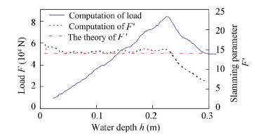
Fig. 9 shows the change of dimensional and dimensionless fluid force of V-buoy in forced fall motion along with the change of water depth. As can be seen from Fig. 9, the dimensional slamming force increases as the submergence depth increases, and then the force begins to decline when the fluid separates from the V-buoy around h=0.23 m. For water entry of a V-buoy at a constant velocity, Faltinsen provided an estimated formula[14] to predict the slamming parameter F' as F/ρv3t. F' is only related to the deadrise angle and is an constant for a given deadrise angle. According to Faltinsen[14], the slamming parameter F' is 14.139 when the deadrise angle is 30°, as shown in Fig. 8. It can be seen that before the separation of fluid from the body, our calculated value of F' coincides well with the estimated value of Faltinsen[14]. After separation of fluid, the calculated F' decreases but the estimated one keeps constant because the formula does not consider the separation of fluid.
|
Fig.9 Time history of the force of the V-buoy in constant speed motion |
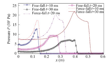
Fig. 10 shows the pressure distribution along the surface of a V-buoy at different times. As can be seen from Fig. 10, for water entry of a V-buoy in free fall motion, the peak pressure value decreases as the body enters water before the motion direction of the body changes. The position corresponding to the peak pressure moves along the edge of the V-buoy, and the maximum slamming pressure occurs near the intersection point between the body and free surface. For water entry of a V-buoy at a constant velocity, the pressure peak value increases as the body enters water before the fluid separates from the body. The position corresponding to peak pressure moves along the edge of the V-buoy and the maximum slamming pressure also occurs near the intersection point between the body and the free surface.
|
Fig.10 Pressure distribution along the V-buoy face |
For water entry of a V-buoy in free fall motion, the velocity of the body declines gradually under the upward fluid force, so the peak slamming pressure decreases gradually. Meanwhile, because the jet root of the fluid (as shown in Fig. 1) on the body moves along the edge of the V-buoy during water entry, the position of peak pressure moves upwards correspondingly. For water entry of a V-buoy in forced motion at a constant velocity, the slamming pressure increases gradually with the increase of water depth. The position of the peak pressure moves upwards along the edge of the V-buoy while the jet root of fluid also moves along the edge of the V-buoy upwards. For the above phenomenon, because the fluid curvature changes sharply at the jet root of fluid, the velocity decreases and the pressure increases, so the peak pressure and the jet root of fluid will move upwards along the edge of the V-buoy.
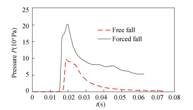
Fig. 11 provides the time histories of dimensional pressure at point A. It can be seen from the figure that the slamming pressure at the same point of the constant velocity motion is always greater than that of the free-fall motion.
|
Fig.11 Predicted pressure time histories of point A |
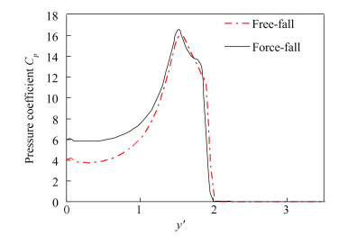
Fig. 12 provides the relation between the pressure coefficient Cp and the dimensionless depth y' when the pressure of point A reaches the maximum value. It can be seen that both the maximum pressure coefficient Cpmax and the dimensionless depth y' corresponding to maximum pressure coefficient Cpmax are the same under these two conditions, which indicates that the pressure coefficient Cpmax in free fall motion can be predicted by using the way of water entry at a constant velocity although the velocity in free motion changes. This would provide an easier way to predict the maximum pressure coefficient, because water entry at a constant velocity will be relatively easy to calculate, no matter in potential flow theory or CFD method.
|
Fig.12 Pressure coefficient Cp in function of the dimensionless entry depth y' |
4 Conclusions
In this paper, FLUENT software was adopted to simulate 2D helicopter V-buoy's free fall and forced fall motion at a constant velocity. The standard k-ε turbulence model and the VOF technique were used to construct and capture the free surface, combining with UDF program and dynamic mesh technique. The physical parameters such as velocity and force were calculated and compared with those of numerical results by Wu et al. [8] and experimental results by El-Mahdi et al. [16] with good agreement achieved. The results of free fall and forced fall motions at the same initial falling speeds were also compared and analyzed. Some conclusions could be drawn as below:
a) For free-fall motion, with the increase of time, the value of slamming peak pressure decreases and the position of peak pressure moves along the V-buoy edge. The maximum slamming pressure occurs in the jet root region. For forced fall motion with a constant velocity, with the increase of the time, the value of slamming peak pressure increases and the position of pressure peak moves along the V-buoy edge. The maximum slamming pressure also occurs in the jet root region.
b) The slamming pressure P and slamming force F of the body in forced fall motion are greater than those in free fall motion.
c) For the pressure coefficient Cp, the maximum pressure coefficient Cpmax and its corresponding dimensionless depth y' in free fall and forced fall motions are equal.
The method and conclusions presented in this paper would provide a basic theoretical support for ditching simulation of helicopters.
| [1] |
Jiang X W. Study of Some Key Problems on Helicopter Emergency Dipping Water Experiment. Wuhan: Wuhan University of Technology, 2010.
(  0) 0) |
| [2] |
Li T, Li M Q, Wu J H. Helicopter ditching scale model test methods. Computer and Digital Engineering, 2015, 10: 1790-1890. DOI:10.3969/j.issn.1672-9722.2015.10.015 (  0) 0) |
| [3] |
Chen L X, Wang Z Z, Ma Y J. Estimation method for the distribution of ditching loads and pressures for helicopters with V bottom. Helicopter Technique, 2014, 2: 5-9. DOI:10.3969/j.issn.1673-1220.2014.02.002 (  0) 0) |
| [4] |
Ma Y J, Wang Z Z, Chen L X. Estimation of impact loads and pressure distribution of a flat-plate helicopter. Helicopter Technique, 2014, 1: 1-5. DOI:10.3969/j.issn.1673-1220.2014.01.001 (  0) 0) |
| [5] |
Yuan L B, Kang M. Simulation of helicopter impacting on calm water. Helicopter Technique, 2016, 1: 15-21. DOI:10.3969/j.issn.1673-1220.2016.02.004 (  0) 0) |
| [6] |
Sun J H, Zhou T, Li M Q, et al. Numerical analysis of emergent airbag deployment and ditching crashworthiness process. Journal of Nanjing University of Aeronautics & Astronautics, 2012(5): 713-717. DOI:10.16356/j.1005-2615.2012.05.019 (  0) 0) |
| [7] |
Zhang J, Zhang Z R, Hong F W. Numerical simulation of initial flow of wedge entry. Journal of Ship Mechanics, 2003, 7(4): 28-35. DOI:10.3969/j.issn.1007-7294.2003.04.005 (  0) 0) |
| [8] |
Wu Guoxiong. Numerical simulation for water entry of a wedge at varying speed by a high order boundary element method. Journal of Marine Science and Application, 2012, 11(2): 143-149. DOI:10.1007/s11804-012-1116-3 (  0) 0) |
| [9] |
Wu G X, Sun H, He Y S. Numerical simulation and experimental study of water entry of a wedge in free fall motion. Journal of Fluids and Structures, 2004, 19(3): 277-289. DOI:10.1016/j.jfluidstructs.2004.01.001 (  0) 0) |
| [10] |
Xu G D, Duan W Y, Wu G X. Numerical simulation of water entry of a cone in free-fall motion. Quarterly Journal of Mechanics and Applied Mathematics, 2011, 64(1): 265-285. DOI:10.1093/qjmam/hbr003 (  0) 0) |
| [11] |
Xu G D, Duan W Y, Wu G X. Simulation of water entry of a wedge through free fall in three degrees of freedom. Proceeding of Royal Society A, 2010, 466: 2219-2239. DOI:10.1098/rspa.2009.0614 (  0) 0) |
| [12] |
Xu G D, Duan W Y, Wu G X. Numerical simulation of oblique water entry of an asymmetrical wedge. Ocean Engineering, 2008, 35(16): 1597-1603. DOI:10.1016/j.oceanng.2008.08.002 (  0) 0) |
| [13] |
Wang F J. The Analysis of Computational Fluid Dynamics— The Theory and Applications of CFD Software. Beijing: Tsinghua University Press, 2004: 126-130.
(  0) 0) |
| [14] |
Faltinsen OM. Hydrodynamics of High-speed Marine Vehicles. Beijing: National Defense Industry Press, 2007: 510-519.
(  0) 0) |
| [15] |
Chen Qingtong, Ni Baoyu, Chen Shuping, et al. Numerical simulation of the water entry of a structure in free fall motion. J. Marine Sci. Appl, 2014, 13(2): 173-177. DOI:10.1007/s11804-014-1242-1 (  0) 0) |
| [16] |
Yettou E-M, Desrochers A, Champoux Y. Experimental study on the water impact of a symmetrical wedge. Fluid Dynamics Research, 2006, 38(1): 47-66. DOI:10.1016/j.fluiddyn.2005.09.003 (  0) 0) |
 2019, Vol. 26


