2. Dongguan Branch, Institute of High Energy Physics, Chinese Academy of Sciences, Dongguan 523803, Guangdong, China
Jet impingement technique has been widely applied in many industrial applications because of its high heat transfer rate. During the last several decades, scores of the experiments and relative numerical methods were studied on the mechanism of the impingement jet flow and the validation of the turbulence models, including different impingement distances, Reynolds numbers, nozzle lips, impingement angles, confines of the stream path, geometries of the nozzle, etc. Especially, a representative test case, in which a fully developed low-Reynolds turbulent jet injecting from a round-long pipe and then impinging perpendicularly upon a flat surface, was of great interest, such as, Baughn and Shimizus[1-2], Cooper[3], Yan[4], Lytle and Webb[5], Brignoni and Garimella[6] and Katti et al.[7] In addition, the heat transfer rate of the confined impingement jet flow also attracted more and more attentions in recent years, which were reported in quite a few investigations[8-12].
The Nusselt number in dimensionless terms is treated as a characteristic parameter describing the level of the local convective heat transfer, thus the accurate prediction of the physics processes of the jet flow and the turbulent heat transfer is desired in complex constructions through high-performance numerical methods but not over-dependence experiments. For different cases, various turbulence models could be applied to suit different impingement cases. A number of investigations on turbulence model have been carried out and validated against the round-long pipe impingement test model. For instance, Craft et al.[13] used three second-moment closures model and one k-ε eddy viscosity model, Yang and Shih[14] used a low-Reynolds standard k-ε model, Kunugi et al.[15] adopted an anisotropic k-ε model, Behnia et al.[16] selected the normal-velocity relaxation turbulence (ν2-f model), Ničeno et al.[17] predicted the jet impingement by Large Eddy Simulation (LES), Merci[18] by a cubic k-ε model, Tiselj et al.[19] by Direct Numerical Simulation approach (DNS), Hadžiabdić and Hanjalić[20] by a combination of DNS and LES (DES), Draksler et al.[21] by RANS approach and shear stress turbulence (SST) eddy viscosity type, Goldberg and Chakravarthy[22] presented a k-l turbulence closure and predicted the impingement jet. Above all, the DNS approach is only one to capture turbulence flow detailed structures but most expensive, LES and DES are time-consuming, though also more accurate, than others because of the dependence of three-dimensional meshes. In two-dimensional axisymmetric calculations of the turbulent jet impingement, Behnia's results[16] showed that the capability of the ν2-f model was superior to the standard k-ε model but poor-performance than the cubic k-ε model. Goldberg's work[22] indicated the k-l model was superior to SST in overall region except in stagnation.
A nonlinear k-ε-fu model by means of the realizability constraint and Cayley-Hamilton theorem, based on the linear model developed by Park and Sung[23], was developed to predict an axisymmetric impinging jet flow[24-25], which had a high performance through comparisons of the k-ε model and ν2-f model. At the same time, another turbulence model, the wall-distance-free low-Re k-ε-fu model, was reported by Goldberg and Palaniswamy[26]. In that model, its transport equation was used for determining the damping function. It was confirmed that Goldberg's three-equation k-ε-fu model could improve the prediction of some flows involving back-flow regions.
In current work, the local Nusselt number and flow parameters of a jet impinging to an isothermal constant temperature plate are calculated using the RANS approach. A refined Goldberg's k-ε-fu model modified in the turbulence production and the realizable time scale is applied to resolve the turbulence. The axisymmertric, compressible Navier-Stokes (N-S) equations based a reynolds averaged method are solved with the finite volume technique. The k-ε transport and the fu damping function are considered as well. The solutions are verified against a set of previous experimental data[1-2, 4, 7] and six excellent turbulence models of Re≈23 000 in aforementioned numerical investigations[16, 18, 21-22, 24, 27] aiming to validate the performance of the present turbulence model.
In the second part of the investigation, the effect of the fully confined impingement round jet on the local Nusselt number for the jet plate and target plate is analyzed. Computations of the symmetry model with present turbulence model are compared with the measurements conducted by Caggese et al.[12] recently. The main purpose of the analysis is to show the level of the heat transfer at different jet-to-plate distances in confined space having a single exit of the jet flow, and also to validate the effectiveness of the refined Goldberg's k-ε-fu model.
2 Mathematical Formulation 2.1 Governing EquationsIn Cartesian tensor notation, the two-dimensional governing equations can be expressed as:
| $ \frac{\partial U_{i}}{\partial x_{i}}=0 $ | (1) |
| $ U_{j} \frac{\partial U_{i}}{\partial x_{j}}=-\frac{1}{\rho} \frac{\partial P}{\partial x_{i}}+\frac{\partial}{\partial x_{j}}\left[v \frac{\partial U_{i}}{\partial x_{j}}-\overline{u_{i} u_{j}}\right] $ | (2) |
According to the law of Reynolds-averaged Navier-Stokes, the instantaneous parameters of the flow consist of the mean and the fluctuating parts. Therefore, the subscript i and j represent the ith and jth components of quantities, U and P are the mean velocity and the pressure, u is the fluctuating velocity, v is the fluid kinematic viscosity, ρ is density respectively, x and y are the corresponding coordinates, and
In accordance with the Boussinesq model, Reynolds stresses are related to the mean strain in an eddy viscosity model, hence the expression of Reynolds stresses can be given as follows:
| $ -\rho \overline{u_{i} u_{j}}=\mu_{t}\left(U_{i, j}+U_{j, i}-\frac{2}{3} U_{k, k} \delta_{i, j}\right)-\frac{2}{3} \rho k \delta_{i, j} $ | (3) |
The eddy-viscosity, expressed by the damping function fμ, density ρ, turbulence kinetic energy k and dissipation rate ε, is shown as:
| $ \mu_{t}=\min \left(f_{\mu}, \tilde{f}_{\mu}\right) \rho k^{2} / \varepsilon $ | (4) |
It is noteworthy that this equation has been modified from the old expression μt=fμρk2/ε in Ref.[16], where the damping coefficient was over-predicted. Thus the transport equations for k, ε and fμ can be modeled as:
| $ \begin{array}{l} \left[ {\begin{array}{*{20}{c}} {\frac{{{\rm{d}}\rho k}}{{{\rm{d}}t}}}\\ {\frac{{{\rm{d}}\rho \varepsilon }}{{{\rm{d}}t}}}\\ {\frac{{{\rm{d}}\rho {f_\mu }}}{{{\rm{d}}t}}} \end{array}} \right] = \frac{\partial }{{\partial {x_i}}}\left[ {\begin{array}{*{20}{c}} {\left( {\mu + \frac{{{\mu _{\rm{t}}}}}{{{\sigma _k}}}} \right)}&{\frac{{\partial k}}{{\partial {x_j}}}}\\ {\left( {\mu + \frac{{{\mu _{\rm{t}}}}}{{{\sigma _\varepsilon }}}} \right)}&{\frac{{\partial \varepsilon }}{{\partial {x_j}}}}\\ {\left( {\mu + \frac{{{\mu _{\rm{t}}}}}{{{\sigma _f}}}} \right)}&{\frac{{\partial {f_\mu }}}{{\partial {x_j}}}} \end{array}} \right] + \\ \;\;\;\;\;\;\;\;\;\left[ {\begin{array}{*{20}{c}} {{{\tilde P}_k} - \rho \varepsilon }\\ {\left( {{C_{\varepsilon 1}}{P_k} - {C_{\varepsilon 2}}\rho \varepsilon } \right)T_{\rm{t}}^{ - 1}}\\ {\mu \frac{{\partial {f_\mu }}}{{\partial {x_j}}}\frac{{\partial {f_\mu }}}{{\partial {x_j}}} - {{\left\{ {{A_\mu }\rho \left( {{C_\mu } - {f_\mu }} \right)} \right\}}^2}\frac{k}{\mu }} \end{array}} \right] \end{array} $ | (5) |
In above formulas, the turbulence production, related to the Reynolds stresses, can be given as Pk=-ρ
| $ \tilde{P}_{k}=\min \left\{P_{k}, C_{\mu}(\rho k)^{2} / \mu_{\mathrm{t}}\right\} $ | (6) |
To get a refinement enhancing the model's as the modify formula of the k-l model in Ref.[22], the realizable time scale is:
| $ T_{\mathrm{t}}=\max \{1, \sqrt{2 / R_{\mathrm{t}}}\} k / \varepsilon $ | (7) |
where Rt=ρk2/με is the turbulence Reynolds number with the fluid viscosity μ.
In equilibrium conditions, the advection and diffusion terms are absent. The damping function only varies in the wall-normal direction under the condition of two-dimensional flow, which depends on its own transport equation. Thus, the following expression is derived from above analyses as:
| $ \tilde{f}_{\mu}=C_{\mu} \frac{\tanh \left(A_{\mu} R_{{\rm t}}^{3 / 4}\right)}{\tanh \left(A_{\varepsilon} R_{{\rm t}}^{3 / 4}\right)} $ | (8) |
The model constants above are given respectively as:
| $ \begin{aligned} C_{\mu}=0.09, \sigma_{\varepsilon}=1.3, \sigma_{k}=1.0, \sigma_{f}=50.0 \\ C_{\varepsilon 1}=1.44, C_{\varepsilon 2}=1.92, A_{\mu}=0.001 \end{aligned} $ |
In the present implementation, the heat flux can be expressed as the following formula:
| $ \nabla q=-C_{\mathrm{p}}\left(\mu / P r+\mu_{\mathrm{t}} / P r_{\mathrm{t}}\right) \nabla T $ | (9) |
where ∇ denotes Hamilton operator, Pr is the Prandtl number, q is the heat transfer rate, Cp is the specific heat at constant pressure, and T is the fluid temperature. The subscript t indicates the turbulence and Prt=0.9 (also given and validated in Ref.[27]), and the molecular Prandtl number Pr is 0.71.
2.2 Numerical ProcedureThe solution of the steady-state at lager times was obtained when the absolute residual errors over all the nodes was less than 10-6. The second-order scheme with out-of-face viscous polynomials was used to discretize the governing equations. The finite volume technique[28] was applied to solved the N-S equation. The fourth-order central-differencing format is selected for the treatment of the viscous term. In the turbulence transport equations, the source terms is evaluated using the same treatment as the two-equation turbulence model reported by Merci[29]. A hybrid-scheme time integration was applied, in which the four-order Runge-Kutta method was used for the explicitly treated terms and the Crank-Nicolson method for the implicitly treated terms, respectively. Details about this hybrid scheme is presented by You[30] and also found in Park's work[25].
3 Validation Test-long Circular Pipe 3.1 Test Case DescriptionA typical test case of a low-Reynolds circular turbulent jet, impinging onto a perpendicular flat surface, has been measured by many researchers. To obtain a fully developed jet at the exit plane, the fluid need to pass along a smooth and sufficiently long round pipe at Reynolds number of 23 000 and then impinges on a heated large plate at a 2 or 6 diameter distance. In fact, the diameter of the pipe is not fixed value but changeable (see Table 1), since the Reynolds number has been a function of characteristic parameters containing the diameter D, the bulk velocity Ub and the properties of the fluid (ρ and μ), consequently expressed as Re=(ρUbD)/μ.
| Table 1 List of experimental conditions at Re≈23 000 in published investigations |
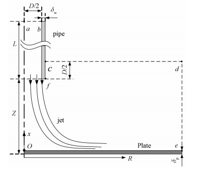
The unheated air is selected as the fluid medium generally. The elaborate set of data is available for the jet-to-plate distance of two-pipe diameters in most tests. The length of the straight long pipe ranges from 56 to 81 diameters and its wall-thickness could be about 0.13 diameters, illustrated the geometry sketch in Fig. 1. Besides, the surface of the heated plate impinged by air jet covers a special thin paint to measure the properties of the flow near the wall, where the temperature difference between jet and plate keeps 20 K so that both can perform the convective heat transfer each other.
|
Fig.1 The geometry sketch of the jet impingement |
3.2 Computational Grid
The specific parameters of simulation are given as: the diameter of the pipe D=25 mm, the length L=72D, the wall thickness δw=0.031 3 D[16], the radius of the plate Rmax=10D and its thickness δp=0 due to that cannot affect the structure of the flow, and the outlet-plate distance Z=2D. The entire computational domain for 2D axisymmetrical model is consisted of the inner part of the whole pipe and the part between the plate and the line overtop the outlet 1/2D, shown as the closure region a-b-c-d-e-O-a in Fig. 1.
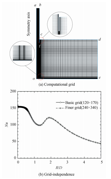
In the region near the wall, the Re is lower as the effect of viscosity. Thus boundary layers with a proper y+ value were built on the region near the wall. In this work, a refined grid near the pipe wall with y+=0.5 is used in computations. The instructed meshes are given in Fig. 2(a). A detail description for the limiting number of constrained wall layers was also given in Wang's work[31]. A non-uniform structured grid of 120×170 cells is used and y+≈0.5 is selected for a high resolution near wall boundaries. Fig. 2(b) shows the grid-independence of a finer doubled-grid solution. The number of cells along the plate is 120 with a geometric distribution. Radially, there are 45 cells within the pipe, where the grid is also re-fined near the axis (Oa) to capture the flow structure at the stagnation point. Axially, the cells of the pipe are uniform and consistent with the downstream grids. There are five equal spacing cells in the thickness of the pipe so that the influence of the lip structure in the jet outlet can be considered.
|
Fig.2 Computational grid and Grid-independence |
3.3 Boundary Conditions
The unheated air of 293 K imposed from the inlet (ab) is fully developed towards the downstream, and the bulk velocity of approximately 13.62 m/s, is derived from the formula of Re=(ρUbD)/μ=23000. There, the velocity of the freestream is negligible. The turbulence level of 1% refers to Ref.[18]. The pipe wall is set to adiabatic wall. The conditions of the static plate surface deems to isothermal constant temperature of 313 K because of small difference in overall impingement plate[1, 18], where the turbulence kinetic energy k can be set to zero and the dissipation rate to
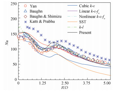
The different turbulence models of the jet impingement with numerical methods, performed under the same conditions as the experiment in Ref.[1], are listed in Table 2, where all turbulence models have been validated through experimental data or verified by other models. Within the k-ε model is over-predictive in the stagnation region, while LES and DNS are accurate but expensive due to the dependence of three-dimensional sophisticated grids, so these models are not illustrated in Fig. 3. From Fig. 3, the result obtained from the present refined Goldberg's k-ε-fu model has good agreement with the experimental data reported.
| Table 2 Overview of turbulence models at Z/D=2 with Re≈23 000 |
|
Fig.3 Profiles of heat transfer coefficient for different turbulent models |
Besides, the prediction of the Nusselt number in the stagnation region is excellent. There are two turbulent models, k-l and nonlinear k-ε-fu models, having excellent results analogous to the present model in the whole region. However, the former is too over-predicted and the latter is little under-predicted in the first peak region. The predictions using the current turbulence model are slightly higher than early experimental data at the second peak, but they are within the range of Katti and Brabhu's recent data[7]. In other radial regions, the profile of the Nusselt number is excellently consistent with the published data, especially with Baughn and Shimizu's.
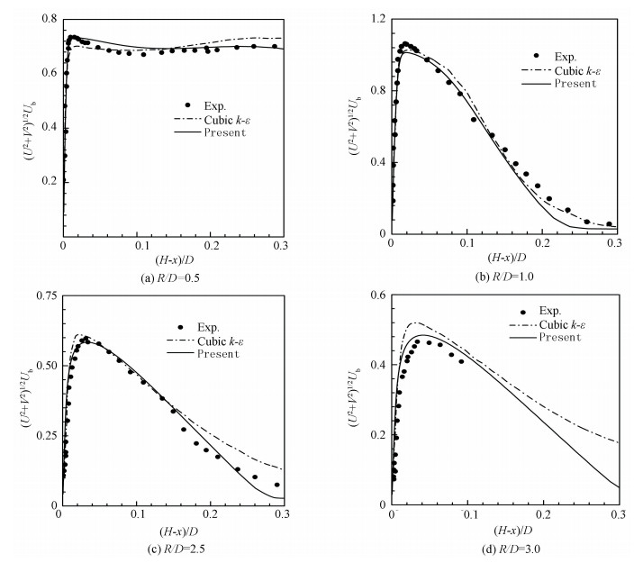
Furthermore, two important parameters to determine the accuracy of the prediction, namely the mean velocity and turbulent shear stress, were used for comparison with the data collected from Refs.[1-5] by Merci and Dick[18]. In their works, it was confirmed that the cubic k-ε turbulence model had good agreement with measurements in Ref.[18]. Thus distributions of the mean velocity with present model compared with data described above are shown in Fig. 4. From Fig. 4, profiles of mean velocity are consistent with the experimental data at different radial positions for jet-to-plate distance Z/D=2.
|
Fig.4 Comparison of mean velocity at R/D=0.5, 1.0, 2.5, 3.0, for Z/D=2 |
4 Effect of Fully Confined Impinging Domain 4.1 Experimental Case
This section investigates the confinement effects of the fully confined impingement jet on the heat transfer coefficient for the impingement plate and the target plate. Results of simulations using the SST turbulence model, with Re=23 350 at different separation distances varying from Z/D=0.5 and 1.5, were validated against the experimental data by Caggese et al.[12]
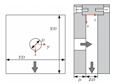
In Caggese's work, the confined geometry consists of a single exit for spent air of the jet, a 5D×5D square target plate for the jet impingement, a jet-plate drilled a hole connected with a single round straight nozzle. The schematic representation of the confined impingement box is shown in Fig. 5, where the arrow indicates the inlet and the outlet of the jet in the box. In experiments, the heated air through the heater mesh fixed on the pipe injects from the hole on the jet-plate and impinges onto the target plate, whose surfaces cover the liquid crystal coat to acquire the local Nusselt number around the whole flow path indirectly. During the impinging, as reported in Ref.[8], the target plate almost keeps a constant temperature.
|
Fig.5 Schematic representation of the confined impingement box |
4.2 Results and Analysis
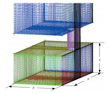
For the numerical simulation, the turbulence model described in section two is used, and other conditions are the same to these given in Ref.[12], such as types of boundary conditions, the quality of mesh grids, the distance of the first grid node and the residuals of the calculated parameters. Given the overall symmetry of the geometry, half of the flow domain is selected for simulation. Structured grids are generated using the grid-generation software ANSYS ICEM and is given in Fig. 6. About 0.73 × 10⁶ hexahedral elements are used for an accurate spatial discretization. Dimensionless distances from centroid to wall of first layer grid, namely y+, are used for near wall regions with different Re numbers. In this work, y+=0.5 and y+=3 are used for the lowest and the highest Re, respectively.
|
Fig.6 Numerical grid of the confined impingement jet |
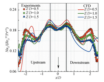
Calculated and experimental local Nusselt numbers at all tested separation distances in x and y centerlines for target plates are given in Fig. 7 and Fig. 8, respectively. For the target plate, all tested separation distances show similar shapes of the local Nusselt number in y direction: two distinct peaks around the ring of which radii are x/D=0.5 and 1.5, and the minimum value is located at the center of the stagnation region. From the left of Fig. 7, the tendency of the experimental data in this confined geometry, referring to the results of Re=23 000, is also coincident with that of the free-impingement, whereas the secondary peak of the confined box is outward than free-impingement by 0.5D, and the primary peaks of both cases decrease slightly and the secondary peaks have a distinct decrease as the increase of the separation distance. In the right of Fig. 7, comparisons between CFD and experiments show the donut shape distribution and the level of the local Nusselt number have agreement except for the region near the secondary peak. As the same to the description of the validation part, the use of the present turbulence model to capture the heat transfer actually, due to a common over-prediction of 6% in the secondary peak, is acceptable in numerical simulation.
|
Fig.7 Local NuD distributions on the target plate at Re=23 350:y- direction, x=0 |
|
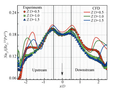
Fig.8 Local NuD distributions on the target plate at Re=23 350: x - direction, y=0 |
In Fig. 8, a degradation of the primary peak in the stagnation appears because of the asymmetric geometry: a confined wall in the upstream direction and a single exit in the downstream. As the Z/D increases, the primary peaks in the wall side keep the same shape to these in Fig. 7 but slightly below the value of the symmetry in the exit side. Additionally, all the secondary peaks at three separation distances are almost disappear but relatively strong for Z/D=0.5. Besides, the declining trend of the profiles is more abrupt, but relatively weak, in the upstream direction than the downstream direction. Note that the CFD results show a similar distribution with experiments within the region fenced by the secondary peak ring in x direction, but the rest region, especially the position and intensity of the secondary peak, is not able to be predicted accurately. This could be attributed to the overestimation of the turbulence model itself and the increase values of GCI discussed in Ref.[12]. In some literatures on numerical solutions of the confined impingement, the secondary peak was common and its intensity was obvious in the results reported as Ref.[33].
5 ConclusionsResults have been presented for the local heat transfer in turbulent impingement jets, impinging onto a flat plate and a fully confined space for the Reynolds number of about 23 000, with a non-linear k-ε-fu turbulence model. Comparison of the numerical results with experimental data shows that the RANS approach with the k-ε-fu model is relatively accurate to be applied for low-Reynolds engineering predictions of local heat transfer. A series of validation tests considering the jet impingement, which is fully developed through a long pipe, show that the local heat transfer prediction is highly affected by the turbulence profile.
The second part of this study aims to investigate the effect of the fully confined impingement jet on the local Nusselt number. The numerical results indicate that the increasing of separation distance has no obvious effect on the local heat transfer in the center region around the first stagnation zone but has a dramatic decline in the second peak inside the confined box. The overestimated predictions of the heat transfer level around the second peak show this model still need to be further improved for the fully confined impingement case.
AcknowledgmentAuthors thank Dr. Alexandros, professor of Group of Thermal Turbomachinery (GTT), Swiss federal Institute of Technology in Lausanne, Switzerland, for his help in experimental data and numerical initial parameters.
| [1] |
Baughn J W, Shimizu S. Heat transfer measurements from a surface with uniform heat flux and an impinging jet. Journal of Heat Transfer, 1989, 111(4): 1096-1098. DOI:10.1115/1.3250776 (  0) 0) |
| [2] |
Baughn J W, Hechanova A E, Yan X. An experimental study of entrainment effects on the heat transfer from a flat surface to a heated circular impinging jet. Journal of Heat Transfer, 1991, 113(4): 1023-1025. DOI:10.1115/1.2911197 (  0) 0) |
| [3] |
Cooper D, Jackson D C, Launder B E, et al. Impinging jet studies for turbulence model assessment—I. Flow-field experiments, International Journal of Heat and Mass Transfer, 1993, 36(10): 2685-2697. DOI:10.1016/S0017-9310(05)80204-2 (  0) 0) |
| [4] |
Yan X. A preheated-wall transient method using liquid crystals for the measurement of heat transfer on external surfaces and in ducts. Previews of Heat and Mass Transfer, 1995, 21(5): 459-460. (  0) 0) |
| [5] |
Lytle D, Webb B W. Air jet impingement heat transfer at low nozzle-plate spacings. International Journal of Heat and Mass Transfer, 1994, 37(12): 1687-1697. DOI:10.1016/0017-9310(94)90059-0 (  0) 0) |
| [6] |
Brignoni L A, Garimella S V. Effects of nozzle-inlet chamfering on pressure drop and heat transfer in confined air jet impingement. International Journal of Heat and Mass Transfer, 2000, 43(7): 1133-1139. DOI:10.1016/S0017-9310(99)00207-0 (  0) 0) |
| [7] |
Katti V, Prabhu S V. Experimental study and theoretical analysis of local heat transfer distribution between smooth flat surface and impinging air jet from a circular straight pipe nozzle. International Journal of Heat and Mass Transfer, 2008, 51(17-18): 4480-4495. DOI:10.1016/j.ijheatmasstransfer.2007.12.024 (  0) 0) |
| [8] |
Fénot M, Vullierme J J, Dorignac E. Local heat transfer due to several configurations of circular air jets impinging on a flat plate with and without semi-confinement. International Journal of Thermal Sciences, 2005, 44(7): 665-675. DOI:10.1016/j.ijthermalsci.2004.12.002 (  0) 0) |
| [9] |
Li H Y, Chiang M H, Chen K Y. Performance analysis of pin-fin heat sinks with confined impingement cooling. IEEE Transactions on Components and Packaging Technologies, 2007, 30(3): 383-389. DOI:10.1109/TCAPT.2007.900052 (  0) 0) |
| [10] |
Taslim M E, Rosso N. Experimental/Numerical study of multiple rows of confined jet impingement normal to a surface at close distances. ASME Turbo Expo 2012: Turbine Technical Conference and Exposition.New York: ASME, 2012, 4: 193-205. DOI: 10.1115/GT2012-68634.
(  0) 0) |
| [11] |
Zukowski M. Heat transfer performance of a confined single slot jet of air impinging on a flat surface. International Journal of Heat and Mass Transfer, 2013, 57(2): 484-490. DOI:10.1016/j.ijheatmasstransfer.2012.10.069 (  0) 0) |
| [12] |
Caggese O, Gnaegi G, Hannema G, et al. Experimental and numerical investigation of a fully confined impingement round jet. International Journal of Heat and Mass Transfer, 2013, 65: 873-882. DOI:10.1016/j.ijheatmasstransfer.2013.06.043 (  0) 0) |
| [13] |
Craft T J, Graham L J W, Launder B E. Impinging jet studies for turbulence model assessment—Ⅱ. An examination of the performance of four turbulence models. International Journal of Heat and Mass Transfer, 1993, 36(10): 2685-2697. DOI:10.1016/S0017-9310(05)80205-4 (  0) 0) |
| [14] |
Yang Z, Shih T H. New time scale based k-epsilon model for near-wall turbulence. AIAA Journal, 1993, 31(7): 1191-1198. DOI:10.2514/3.11752 (  0) 0) |
| [15] |
Kunugi T, Yokomine T, Ichimiya K. Numerical and experimental study on heat transfer of an impinging turbulent plane jet with confined wall. Heat Transfer in Turbulent Flows, 1993, 246: 25-31. (  0) 0) |
| [16] |
Behnia M, Parneix S, Durbin P A. Prediction of heat transfer in an axisymmetric turbulent jet impinging on a flat plate. International Journal of Heat and Mass Transfer, 1998, 41(12): 1845-1855. DOI:10.1016/S0017-9310(97)00254-8 (  0) 0) |
| [17] |
Ničeno B, Dronkers A D T, Hanjalić K. Turbulent heat transfer from a multi-layered wall-mounted cube matrix: a large eddy simulation. International Journal of Heat and Fluid Flow, 2002, 23(2): 173-185. DOI:10.1016/S0142-727X(01)00147-3 (  0) 0) |
| [18] |
Merci B, Dick E. Heat transfer predictions with a cubic k-ε model for axisymmetric turbulent jets impinging onto a flat plate. International Journal of Heat and Mass Transfer, 2003, 46(3): 469-480. DOI:10.1016/S0017-9310(02)00300-9 (  0) 0) |
| [19] |
Tiselj I, Horvat A, Mavko B, et al. Wall properties and heat transfer in near-wall turbulent flow. Numerical Heat Transfer, Part A: Applications, 2004, 46(7): 717-729. DOI:10.1080/104077890504005 (  0) 0) |
| [20] |
Hadžiabdić M, Hanjalić K. Vertical structures and heat transfer in a round impinging jet. Journal of Fluid Mechanics, 2008, 596: 221-260. DOI:10.1017/S002211200700955X (  0) 0) |
| [21] |
Draksler M, Končar B. Analysis of heat transfer and flow characteristics in turbulent impinging jet. Nuclear Engineering and Design, 2011, 241(4): 1248-1254. DOI:10.1016/j.nucengdes.2010.03.037 (  0) 0) |
| [22] |
Goldberg U, Chakravarthy S. A k-L Turbulence Closure for Wall-Bounded Flows. Proceedings of the 35th AIAA Fluid Dynamics Conference and Exhibit. Washington, DC: AIAA, 2005.4638. DOI: 10.2514/6.2005-4638.
(  0) 0) |
| [23] |
Park T S, Sung H J. A new low-Reynolds-number k-epsilon-fμ model for predictions involving multiple surfaces. Fluid Dynamics Research, 1997, 20(1-6): 97-113. DOI:10.1016/S0169-5983(96)00047-0 (  0) 0) |
| [24] |
Park T S, Sung H J, Suzuki K. Development of a nonlinear near-wall turbulence model for turbulent flow and heat transfer. International Journal of Heat and Fluid Flow, 2003, 24(1): 29-40. DOI:10.1016/S0142-727X(02)00211-4 (  0) 0) |
| [25] |
Park T S, Choi H S, Suzuki K. Nonlinear k-ε-fμ model and its application to the flow and heat transfer in a channel having one undulant wall. International Journal of Heat and Mass Transfer, 2004, 47(10-11): 2403-2415. DOI:10.1016/j.ijheatmasstransfer.2003.10.038 (  0) 0) |
| [26] |
Goldberg U, Palaniswamy S. The k-ε-fμ turbulence closure model. Computer Methods in Applied Mechanics and Engineering, 1999, 179(1-2): 139-149. DOI:10.1016/S0045-7825(99)00035-3 (  0) 0) |
| [27] |
Park T S, Sung H J. Development of a near-wall turbulence model and application to jet impingement heat transfer. International Journal of Heat and Fluid Flow, 2001, 22(1): 10-18. DOI:10.1016/S0142-727X(00)00069-2 (  0) 0) |
| [28] |
Cadafalch J, Pérez-Segarra C D, Consul R, et al. Verification of finite volume computations on steady-state fluid flow and heat transfer. Journal of Fluids Engineering, 2002, 124(1): 11-21. DOI:10.1115/1.1436092 (  0) 0) |
| [29] |
Merci B, Steelant J, Vierendeels J, et al. Computational treatment of source terms in two-equation turbulence models. AIAA Journal, 2000, 38(11): 2085-2093. DOI:10.2514/2.870 (  0) 0) |
| [30] |
You J, Choi H, Yoo J Y. A modified fractional step method of keeping a constant mass flow rate in fully developed channel and pipe flows. KSME International Journal, 2000, 14(5): 547-552. DOI:10.1007/BF03185657 (  0) 0) |
| [31] |
Wang L, Liu L, Tian W, et al. Research of phase separation phenomenon in two-phase bubbly flow in T-junction J. Nuclear Power Engineering, 2014, 35(2): 53-57. (  0) 0) |
| [32] |
Kubacki S, Dick E. Simulation of plane impinging jets with k-ω based hybrid RANS/LES models. International Journal of Heat and Fluid Flow, 2010, 31(5): 862-878. DOI:10.1016/j.ijheatfluidflow.2010.04.011 (  0) 0) |
| [33] |
Behnia M, Parneix S, Shabany Y, et al. Numerical study of turbulent heat transfer in confined and unconfined impinging jets. International Journal of Heat and Fluid Flow, 1999, 20(1): 1-9. DOI:10.1016/S0142-727X(98)10040-1 (  0) 0) |
 2019, Vol. 26


