The Buck converter is an important component of a DC-DC converter, its working principle is different from a Boost converter because it has the ability to reduce direct-current (DC) voltage, and has been extensively used in many applications, such as power electronic technology and computer technology[1]. Modeling is a significant procedure for devising converters to meet actual demands, for example, the accuracy of the model has a crucial influence on capability of the final design. Thus a lot of effort has been put into establishing a proper model and find some better analysis methods. In order to research Buck converters, some appropriate models and analysis methods have been proposed in recent years[1-8]. For instance, it is assumed that its characteristic frequency is much smaller than its switching frequency, and the averaged model, which is used to derive the small signal model, can be obtained by averaging the circuit variable during the switching period. This is also helpful to study the dynamic characteristics of Buck converter in the low frequency domain[1-4]. In addition, the averaged model can not be used to analyze the dynamic characteristics of high frequency region, so the discrete model has been proposed to analyze the overall dynamic behavior. This model is mainly used to solve the differential equations that are different under different operational conditions, and then circuit variables will be sampled and collected at a certain moment. Researchers usually use the discrete model to identify nonlinear behavior and complete the accurate simulation of the Buck converter[5-8]. All the above research results are a good reference for researchers to design an accurate Buck converter. However, the above findings gotten under this assumption is that both actual inductor and actual capacitor are integer order[1-8].
With the rapid development of integer calculus and its wide range of applications[9-11], researchers gradually turned their attention to fractional calculus applications, and a lot of meaningful results have been obtained[12-20]. Most noteworthy, the research results of actual inductor and actual capacitor prove that they are all actually fractional order and must be analyzed by means of fractional correlation theory[15-20]. For instance, an actual inductor was proved actually fractional order by Westerlund and he also constructed its fractional order model[15]. The order of fractional order capacitor were also measured and obtained under different dielectrics[16]. It was pointed out the integer order capacitor cannot exist in reality since its impedance modality would go against mathematical principles[17]. The fractional Chua's circuit was successfully realized by using the fractional order model of inductor and capacitor, and the rationality of theoretical analysis were indicated[18]. Fractional order capacitors with different orders were also developed by using diverse fractal structures[19]. It was pointed out that an inductor with a different order would be produced because of skin effect shown by Tenreiro Machado[20]. So, the fractional order model of inductor and capacitor should be established to research true electrical characteristics. So, a problem was subsequently produced: why was it possible to approximate the actual circuit by using the data of integer order model? A primary reason for this problem is that the fractional order is approximately equal to 1, and accordingly their dynamic behavior can be approximately described in terms of the integer order model. This approximation will cause error results if the fractional order is a little far from 1, such as the capacitor with order of 0.59 and inductor with different order[19-20]. Therefore, a fractional order model of the Buck converter should be constructed. So far, the research on fractional order systems is becoming more and more mature, and a lot of research results on fractional order modeling of DC-DC converters have been generated[21-27]. For instance, the fractional order Buck-Boost DC/DC converter were constructed by using the state average modeling method, and the following two modes were also included: pseudo continuous conduction mode(PCCM) and discontinuous conduction mode(DCM)[22-24]. The fractional order modeling problem of the Boost converter was also solved by the same method[25-27]. The above research results and methods are also useful for modeling of Buck converter.
The contents are as follows.Some basic fractional theories on fractional order inductors and capacitors are given in Section 2. The fractional order state-space averaging model of a Buck converter in CCM is established and the transfer functions are provided in Section 3. The parameter condition that ensures converter work in CCM is also given. Both numerical simulation and circuit experiments are completed to verify the theoretical analysis, and some dynamic behaviors of the current-controlled Buck converter are investigated in Section 4. Finally, some conclusions are given.
2 Fundamental Theory 2.1 Fractional CalculusOperations of general differentiations and integrations to non-integer order can be achieved by using fractional calculus. It generalizes the traditional calculus, but it has a wider scope of application[21].The fundamental operator aDtγ is:
| $ {}_aD_t^\gamma = \left\{ {\begin{array}{*{20}{c}} {\frac{{{{\rm{d}}^\gamma }}}{{{\rm{d}}{t^\gamma }}},}&{\gamma > 0}\\ {1,}&{\gamma = 0}\\ {\int_a^t {{{({\rm{d}}\tau )}^{ - \gamma }}} ,}&{\gamma < 0} \end{array}} \right. $ | (1) |
where γ(γ∈ℝ) is the order, a and t represent the bounds.
With respect to fractional calculus, there are three main definitions: Grunwald-Letnikov(GL) definition, Riemann-Liouville (RL) definition, and Caputo definition[22].
Caputo definition is:
| $ {}_aD_t^\gamma f(t) = \frac{1}{{\Gamma (n - \gamma )}}\int_a^t {\frac{{{f^{(n)}}(\tau )}}{{{{(t - \tau )}^{\gamma - n + 1}}}}} {\rm{d}}\tau $ | (2) |
where Γ( ) is the Gamma function and n∈N is the first integer which is not less than γ, n-1 < γ < n.
It meets the following condition by means of Laplace transform:
| $ L\left\{ {_aD_t^\gamma f(t)} \right\} = {s^\gamma }F(s) - \sum\limits_{k = 0}^{n - 1} {{s^{\gamma - k - 1}}} {f^{(m)}}(0) $ | (3) |
It satisfies the following form for zero initial condition by means of Laplace transform:
| $ L\left\{ {_aD_t^\gamma f(t)} \right\} = {s^\gamma }F(s) $ | (4) |
Theoretical calculations are implemented based on the Caputo derivative and the more specific initial condition x(0). Hartley and Lorenzo discuss the error arising from using the Laplace transform of Caputo derivative[28]. It is now pretty well established that the initial state of a fractional differential equation can be accurately represented by the weighted integral of z(ω, 0)[29]. Nevertheless, for convenience, the Caputo derivative and the initial condition x(0) are adopted on the basis of the acceptable error.
2.2 The Fractional Order Model of Capacitor and InductorWesterlund[15] proposed a new theory about capacitor based on fractional calculus in 1994, the current corresponding to the input voltage is:
| $ i = {C_f}\frac{{{{\rm{d}}^\beta }u}}{{{\rm{d}}{t^\beta }}},0 < \beta < 1 $ | (5) |
where Cf and β represents the capacitance and the order, and they are related to the type of dielectric and the loss of the capacitor respectively. Capacitor materials were also provided by Westerlund.
Westerlund[16] also created a fractional order model of inductor, which has the following form:
| $ u = {L_f}\frac{{{{\rm{d}}^\alpha }i}}{{{\rm{d}}{t^\alpha }}},0 < \alpha < 1 $ | (6) |
where Lf and α represents the inductance and the order of inductor.
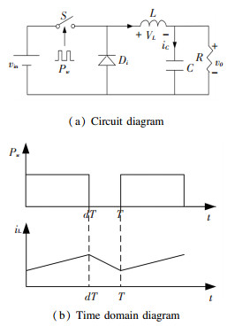
3 Modeling of Fractional Order Buck Converter 3.1 The Mathematical ModelThe circuit structure is given in Fig. 1(a). It works as follows: Pw is a period signal, when a high level Pw appears, switch S is closed, there is no conductive diode, this mode will last for a time interval (0, dT), d and T represent the duty cycle and switching period respectively. Then when a low level Pw appears, switch S is off, there is a conductive diode, this mode will last for a time interval (dT, T). iL, v0, and vin represent the inductor current, output voltage and input voltage respectively. Due to the Buck converter operating in CCM, there are only two switching modes, and the time domain waveform of its inductance current is given in Fig. 1(b).The state equations are as follows.
|
Fig.1 The Buck converter in CCM |
When S is closed,
| $ \left[ {\begin{array}{*{20}{c}} {\frac{{{{\rm{d}}^\alpha }{i_L}}}{{{\rm{d}}{t^\alpha }}}}\\ {\frac{{{{\rm{d}}^\beta }{v_0}}}{{{\rm{d}}{t^\beta }}}} \end{array}} \right] = \left[ {\begin{array}{*{20}{c}} 0&{ - \frac{1}{L}}\\ {\frac{1}{C}}&{ - \frac{1}{{RC}}} \end{array}} \right]\left[ {\begin{array}{*{20}{c}} {{i_L}}\\ {{v_0}} \end{array}} \right] + \left[ {\begin{array}{*{20}{c}} {\frac{1}{L}}\\ 0 \end{array}} \right]{v_{{\rm{in}}}} $ | (7) |
When S is off,
| $ \left[ {\begin{array}{*{20}{c}} {\frac{{{{\rm{d}}^\alpha }{i_L}}}{{{\rm{d}}{t^\alpha }}}}\\ {\frac{{{{\rm{d}}^\beta }{v_0}}}{{{\rm{d}}{t^\beta }}}} \end{array}} \right] = \left[ {\begin{array}{*{20}{c}} 0&{ - \frac{1}{L}}\\ {\frac{1}{C}}&{ - \frac{1}{{RC}}} \end{array}} \right]\left[ {\begin{array}{*{20}{c}} {{i_L}}\\ {{v_0}} \end{array}} \right] + \left[ {\begin{array}{*{20}{l}} 0\\ 0 \end{array}} \right]{v_{{\rm{in}}}} $ | (8) |
So the mathematical model of the fractional order Buck converter described by Eq.(7) and (8) is affected by α and β.
3.2 State-Space Averaging ModelDue to the distinctive working characteristics, circuit variables, such as inductor current iL and output voltage v0, have been affected by the high frequency switching harmonics. To eliminate these effects, a circuit variable should be averaged over one switching period, i.e.,
| $ \langle x\rangle = \frac{1}{T}\int_t^{t + T} x {\rm{d}}\tau $ | (9) |
where x represent a random circuit variable.
According to the properties of fractional calculus, its fractional-order form is obtained:
| $ \frac{{{{\rm{d}}^\gamma }\langle x\rangle }}{{{\rm{d}}{t^\gamma }}} = \frac{{{{\rm{d}}^\gamma }}}{{{\rm{d}}{t^\gamma }}}\left( {\frac{1}{T}\int_t^{t + T} x {\rm{d}}\tau } \right) = \frac{1}{T}\int_t^{t + T} {\frac{{{{\rm{d}}^\gamma }x}}{{{\rm{d}}{t^\gamma }}}} {\rm{d}}\tau = \left\langle {\frac{{{{\rm{d}}^\gamma }x}}{{{\rm{d}}{t^\gamma }}}} \right\rangle $ | (10) |
where γ is the order and 0 < γ < 1.
Above all, state-space averaging model of fractional order Buck converter in CCM can be created.
Average values 〈iL〉, 〈v0〉, 〈vin〉 and d can be defined as the following forms:
| $ \left\{ {\begin{array}{*{20}{l}} {\left\langle {{v_{{\rm{in }}}}} \right\rangle = {V_{{\rm{in }}}} + {{\hat v}_{{\rm{in }}}}}\\ {\left\langle {{v_0}} \right\rangle = {V_0} + {{\hat v}_0}}\\ {d = D + \hat d}\\ {\left\langle {{i_L}} \right\rangle = {I_L} + {{\hat i}_L}} \end{array}} \right. $ | (11) |
where IL, V0, D, and Vin are the DC components of iL, v, d, and vin respectively, îL,
State-space averaging model is as follows:
| $ \left[ {\begin{array}{*{20}{c}} {\frac{{{{\rm{d}}^\alpha }\left\langle {{i_L}} \right\rangle }}{{{\rm{d}}{t^\alpha }}}}\\ {\frac{{{{\rm{d}}^\beta }\left\langle {{v_0}} \right\rangle }}{{{\rm{d}}{t^\beta }}}} \end{array}} \right] = \left[ {\begin{array}{*{20}{c}} 0&{ - \frac{1}{L}}\\ {\frac{1}{C}}&{ - \frac{1}{{CR}}} \end{array}} \right]\left[ {\begin{array}{*{20}{c}} {\left\langle {{i_L}} \right\rangle }\\ {\left\langle {{v_0}} \right\rangle } \end{array}} \right] + \left[ {\begin{array}{*{20}{c}} {\frac{d}{L}}\\ 0 \end{array}} \right]\left\langle {{v_{{\rm{in}}}}} \right\rangle $ | (12) |
Eq.(12) can be rewritten:
| $ \begin{array}{l} \left[ {\begin{array}{*{20}{l}} {\frac{{{{\rm{d}}^\alpha }{I_L}}}{{{\rm{d}}{t^\alpha }}} + \frac{{{{\rm{d}}^\alpha }{{\hat i}_L}}}{{{\rm{d}}{t^\alpha }}}}\\ {\frac{{{{\rm{d}}^\beta }{V_0}}}{{{\rm{d}}{t^\beta }}} + \frac{{{{\rm{d}}^\beta }{{\hat v}_0}}}{{{\rm{d}}{t^\beta }}}} \end{array}} \right] = \left[ {\begin{array}{*{20}{c}} 0&{ - \frac{1}{L}}\\ {\frac{1}{C}}&{ - \frac{1}{{CR}}} \end{array}} \right]\left[ {\begin{array}{*{20}{c}} {{I_L} + {{\hat i}_L}}\\ {{V_0} + {{\hat v}_0}} \end{array}} \right] + \\ \;\;\;\;\;\;\;\;\;\;\;\;\;\;\;\;\;\;\;\;\;\;\;\left[ {\begin{array}{*{20}{c}} {\frac{{D + \hat d}}{L}}\\ 0 \end{array}} \right]\left( {{V_{{\rm{in}}}} + {{\hat v}_{{\rm{in}}}}} \right) \end{array} $ | (13) |
DC components in Eq.(13) are as follows:
| $ \left[ {\begin{array}{*{20}{c}} {\frac{{{{\rm{d}}^\alpha }{I_L}}}{{{\rm{d}}{t^\alpha }}}}\\ {\frac{{{{\rm{d}}^\beta }{V_0}}}{{{\rm{d}}{t^\beta }}}} \end{array}} \right] = \left[ {\begin{array}{*{20}{c}} 0&{ - \frac{1}{L}}\\ {\frac{1}{C}}&{ - \frac{1}{{CR}}} \end{array}} \right]\left[ {\begin{array}{*{20}{c}} {{I_L}}\\ {{V_0}} \end{array}} \right] + \left[ {\begin{array}{*{20}{c}} {\frac{D}{L}}\\ 0 \end{array}} \right]{V_{{\rm{in}}}} $ | (14) |
The quiescent operation point is as follows:
| $ \left[ {\begin{array}{*{20}{c}} {{I_L}}\\ {{V_0}} \end{array}} \right] = \left[ {\begin{array}{*{20}{c}} {\frac{{{V_0}}}{R}}\\ {D{V_{{\rm{in}}}}} \end{array}} \right] $ | (15) |
The voltage ratio is defined as follows:
| $ M = \frac{{{V_0}}}{{{V_{{\rm{in}}}}}} = D $ | (16) |
AC components in Eq.(13) are as follows:
| $ \left[ {\begin{array}{*{20}{c}} {\frac{{{{\rm{d}}^\alpha }{{\hat i}_L}}}{{{{\rm{d}}^\alpha }}}}\\ {\frac{{{{\rm{d}}^\beta }{{\hat v}_0}}}{{{\rm{d}}{t^\beta }}}} \end{array}} \right] = \left[ {\begin{array}{*{20}{c}} 0&{ - \frac{1}{L}}\\ {\frac{1}{C}}&{ - \frac{1}{{CR}}} \end{array}} \right]\left[ {\begin{array}{*{20}{c}} {{{\hat i}_L}}\\ {{{\hat v}_0}} \end{array}} \right] + \left[ {\begin{array}{*{20}{c}} {\frac{{D + \hat d}}{L}}\\ 0 \end{array}} \right]{\hat v_{{\rm{in}}}} + \left[ {\begin{array}{*{20}{c}} {\frac{{\hat d}}{L}}\\ 0 \end{array}} \right]{V_{{\rm{in}}}} $ | (17) |
where
| $ \left[ {\begin{array}{*{20}{c}} {\frac{{{{\rm{d}}^\alpha }{{\hat i}_L}}}{{{\rm{d}}{t^\alpha }}}}\\ {{\rm{d}}{t^\alpha }}\\ {\frac{{{{\rm{d}}^\beta }{{\hat v}_0}}}{{{\rm{d}}{t^\beta }}}} \end{array}} \right] = \left[ {\begin{array}{*{20}{c}} 0&{ - \frac{1}{L}}\\ {\frac{1}{C}}&{ - \frac{1}{{CR}}} \end{array}} \right]\left[ {\begin{array}{*{20}{c}} {{{\hat i}_L}}\\ {{{\hat v}_0}} \end{array}} \right] + \left[ {\begin{array}{*{20}{c}} {\frac{D}{L}}\\ 0 \end{array}} \right]{{\hat v}_{{\rm{in}}}} + \left[ {\begin{array}{*{20}{c}} {\frac{1}{L}}\\ 0 \end{array}} \right]{V_{{\rm{in}}}}\hat d $ | (18) |
Using Caputo fractional calculus definition and treating the input voltage Vin as a constant, then the inductor current ripple ΔiL in (0, DT) can be obtained as
| $ \Delta {i_L} = \frac{{(1 - D){V_{{\rm{in}}}}{{(DT)}^\alpha }}}{{L\alpha \Gamma (\alpha )}} $ | (19) |
where Γ( ) is the Gamma function. The duty cycle D, the input voltage Vin, the switching period T, the inductance L, and the order of inductor α, above all of these will affect the inductor current ripple ΔiL. When α is increased, ΔiL is reduced.
The maximum and minimum values of inductor current are
| $ \left\{ {\begin{array}{*{20}{l}} {{i_{L{\rm{max}}}} = {I_L} + \frac{1}{2}\Delta {i_L} = \frac{{D{V_{{\rm{in}}}}}}{R} + \frac{{(1 - D){V_{{\rm{in}}}}{{(DT)}^\alpha }}}{{2L\alpha \Gamma (\alpha )}}}\\ {{i_{\mathit{L}{\rm{min}}}} = {I_L} - \frac{1}{2}\Delta {i_L} = \frac{{D{V_{{\rm{in}}}}}}{R} - \frac{{(1 - D){V_{{\rm{in}}}}{{(DT)}^\alpha }}}{{2L\alpha \Gamma (\alpha )}}} \end{array}} \right. $ | (20) |
Using Caputo definition and Adomian decomposition method, then the output voltage ripple Δv0 can be obtained as
| $ \Delta {v_0} = \left[ {1 - {E_\beta }\left( { - \frac{{{{(DT)}^\beta }}}{{RC}}} \right)} \right]{V_{{\rm{OT}}}} $ | (21) |
where Eβ( ) is the Mittag-Leffler function and VOT is the value of output voltage when the switch is on.
The approximate expression of VOT is
| $ {V_{{\rm{OT}}}} = \frac{1}{2}\Delta {v_0} + {V_0} $ | (22) |
So,
| $ {V_{{\rm{OT}}}} = \frac{{2D{V_{{\rm{in}}}}}}{{1 + {E_\beta }\left( { - \frac{{{{(DT)}^\beta }}}{{RC}}} \right)}} $ | (23) |
Substituting Eq.(15) and (23) into inequality (21), the following inequality is obtained:
| $ \Delta {v_0} = \frac{{2D{V_{{\rm{in}}}}\left[ {1 - {E_\beta }\left( { - \frac{{{{(DT)}^\beta }}}{{RC}}} \right)} \right]}}{{1 + {E_\beta }\left( { - \frac{{{{(DT)}^\beta }}}{{RC}}} \right)}} $ | (24) |
The duty cycle D, the input voltage Vin, the switching period T, the capacitor C, load resistance R, and the order of capacitor β, above all of these will affect the output voltage ripple Δv0. When β is increased, Δv0 is reduced.
To keep the Buck converter operating in CCM, the inductor current must be greater than 0, i.e.,
| $ {I_L} > \frac{1}{2}\Delta {i_L} $ | (25) |
Substituting Eq.(15) and (19) into inequality (25), the following inequality is obtained:
| $ \frac{L}{{R{T^\alpha }}} \ge \frac{{(1 - D){D^\alpha }}}{{2D\alpha \Gamma (\alpha )}} $ | (26) |
To ensure the Buck converter operates in CCM, the inductance L, load resistance R, the switching period T, duty cycle D, and the order of inductor α should be all considered. Working conditions of inductor L and load resistance R can be clearly gained. It is also obtained: when the order of inductor α becomes larger, the Buck converter is easy to operate in CCM. Particularly, when α=1, Eq.(26) is the same as the result of the integer order model.
According to Eq.(18), the Laplace transform of converter equations under the condition of zero initial value is obtained as follows:
| $ \left\{ {\begin{array}{*{20}{l}} {{s^\alpha }{{\hat i}_L}(s) = \frac{{D{{\hat v}_{{\rm{in}}}}(s)}}{L} - \frac{{{{\hat v}_0}(s)}}{L} + \frac{{{V_{{\rm{in}}}}}}{L}\hat d(s)}\\ {{s^\beta }{{\hat v}_0}(s) = \frac{{{{\hat i}_L}(s)}}{C} - \frac{{{{\hat v}_0}(s)}}{{CR}}} \end{array}} \right. $ | (27) |
The transfer function of
| $ {G_{{r_0}{v_{{\rm{in}}}}}}(s) = {\left. {\frac{{{{\hat v}_0}(s)}}{{{{\hat v}_{{\rm{in}}}}(s)}}} \right|_{\hat d(s) = 0}} = \frac{D}{{LC{s^{\alpha + \beta }} + L{s^\alpha }/R + 1}} $ | (28) |
The transfer function of
| $ {G_{{v_0}d}}(s) = {\left. {\frac{{{{\hat v}_0}(s)}}{{\hat d(s)}}} \right|_{{{\hat v}_{{\rm{in}}(s)}} = 0}} = \frac{{{V_{{\rm{in}}}}}}{{LC{s^{\alpha + \beta }} + L{s^\alpha }/R + 1}} $ | (29) |
The transfer function of
| $ {G_{{i_L}{v_{{\rm{in}}}}}}(s) = {\left. {\frac{{{{\hat i}_L}(s)}}{{{{\hat v}_{{\rm{in}}}}(s)}}} \right|_{\hat d(s) = 0}} = \frac{{DC\left( {{s^\beta } + 1/CR} \right)}}{{LC{s^{\alpha + \beta }} + L{s^\alpha }/R + 1}} $ | (30) |
The transfer function of
| $ {G_{{i_L}d}}(s) = {\left. {\frac{{{{\hat i}_L}(s)}}{{\hat d(s)}}} \right|_{{{\hat v}_{{\rm{in}}}}(s) = 0}} = \frac{{{V_{{\rm{in}}}}\left( {{s^\beta } + 1/CR} \right)}}{{LC{s^{\alpha + \beta }} + L{s^\alpha }/R + 1}} $ | (31) |
It is easy to find orders of the inductor and capacitor that have an effect on transfer functions. That means fractional orders can be considered as extra parameters. Integer order transfer functions can be derived when orders are 1, and integer order model can be seen as a special case of fractional order model.
4 Experimental Research and Dynamic AnalysisThe theoretical analysis is verified by the numerical and circuit simulation experiments, and dynamic analysis is used to research how the order affects dynamic behavior of a current-mode controlled fractional order Buck converter.
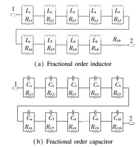
4.1 Approximation Circuit Models of Fractional Order Capacitor and InductorApproximation circuit models of capacitor and inductor are obtained based on analog fractance circuit and the improved Oustaloup approximation algorithm[26-27].Fractional order circuit elements are approximately achieved by choosing the chain structure as the fractance unit. The approximation circuit models are shown in Fig. 2(a) and (b).
|
Fig.2 Approximation circuit models |
When L=3 mH, α=0.8, the respective resistance values are:
| $ {{R_{L1}} = 7.16{\rm{k}}\Omega ,{R_{L2}} = 340.84\Omega } $ |
| $ {{R_{L3}} = 34.25\Omega ,{R_{L4}} = 3.54\Omega } $ |
| $ {{R_{L5}} = 367{\rm{m}}\Omega ,{R_{L6}} = 38{\rm{m}}\Omega } $ |
| $ {{R_{L7}} = 4{\rm{m}}\Omega ,{R_{L8}} = 0.4{\rm{m}}\Omega } $ |
| $ {{R_{L9}} = 42{\rm{ \mathsf{ μ} }}\Omega ,{R_{L10}} = 5{\rm{ \mathsf{ μ} }}\Omega } $ |
The respective inductance values are:
| $ {{L_1} = 95{\rm{ \mathsf{ μ} H}},{L_2} = 77{\rm{ \mathsf{ μ} H}},{L_3} = 131.6{\rm{ \mathsf{ μ} H}}} $ |
| $ {{L_4} = 231.6{\rm{ \mathsf{ μ} H}},{L_5} = 408{\rm{ \mathsf{ μ} H}},{L_6} = 719.4{\rm{ \mathsf{ μ} H}}} $ |
| $ {{L_7} = 1.268{\rm{mH}},{L_8} = 2.235{\rm{mH}},{L_9} = 3.934{\rm{mH}}} $ |
When C=100 μH, β=0.8, the respective resistance values are:
| $ {{R_{C1}} = 20{\rm{m}}\Omega ,{R_{C2}} = 160{\rm{m}}\Omega } $ |
| $ {{R_{C3}} = 1.5\Omega ,{R_{C4}} = 14.6\Omega } $ |
| $ {{R_{C5}} = 141\Omega ,{R_{C6}} = 1.36{\rm{k}}\Omega } $ |
| $ {{R_{C7}} = 13.131{\rm{k}}\Omega ,{R_{C8}} = 126.742{\rm{k}}\Omega } $ |
| $ {R_{C9}} = 1.222{\rm{M}}\Omega ,{R_{C10}} = 102.85{\rm{M}}\Omega $ |
The respective capacitance values are:
| $ {{C_1} = 6.5{\rm{ \mathsf{ μ} F}},{C_2} = 13.98{\rm{ \mathsf{ μ} F}}} $ |
| $ {{C_3} = 24.5{\rm{ \mathsf{ μ} F}},{C_4} = 43.2{\rm{ \mathsf{ μ} F}}} $ |
| $ {{C_5} = 76.2{\rm{ \mathsf{ μ} F}},{C_6} = 134.2{\rm{ \mathsf{ μ} F}}} $ |
| $ {{C_7} = 236.6{\rm{ \mathsf{ μ} F}},{C_8} = 417{\rm{ \mathsf{ μ} F}}} $ |
| $ {{C_9} = 736{\rm{ \mathsf{ μ} F}},{C_{10}} = 560{\rm{ \mathsf{ μ} F}}} $ |
The mathematical model of fractional order Buck converter is built by the improved Oustaloup approximation algorithm in Fig. 3(a). Fractional Int s-α is a fractional integral unit, and its internal structure is given[27]. The switching frequency is selected as f=25 kHz and the corresponding rotational frequency is ω=2πf=1.57×10⁵ rad/s, other parameters are: ωh=2×10⁵ rad/s, ωb= 5×10⁻⁶ rad/s, N=8. Simulation parameters are as follows: vin=20 V, L=3 mH, C=100 μF, d=0.6, f= 25 kHz, α=0.8, β=0.8.

|
Fig.3 Models of fractional order Buck converter |
When α=0.8, β=0.8, according to Eq. (26), the load resistance value of fractional order Buck converter operating in the critical state is obtained: R=41.634 5 Ω. When R < 41.634 5 Ω, the converter works in CCM, so the load resistance value is chosen as: R=30 Ω. The circuit simulation model is shown in Fig. 3(b).
The time domain waveforms of inductor current iL and output voltage v0 are shown in Fig. 4. Clearly, the Buck converter works in CCM. The experimental and theoretical values are shown in Table 1. It can be found that results of numerical simulation and theoretical analysis are consistent, so the theoretical analysis is correct.

|
Fig.4 The waveform of fractional order Buck converter |
| Table 1 Results of fractional order Buck converter |
The comparison between the mathematical model and the circuit model is given in Fig. 5. Due to non-ideal circuit elements, the experimental result of the circuit model is slightly different from the numerical simulation. The correctness of the theoretical analysis is further verified.

|
Fig.5 Comparison results of fractional order mathematical model and circuit model |
4.2.2 Simulation results of integer order Buck converter
When the fractional integral element is changed into an integral unit of integral order, an integer order mathematical model and a circuit model can be obtained.
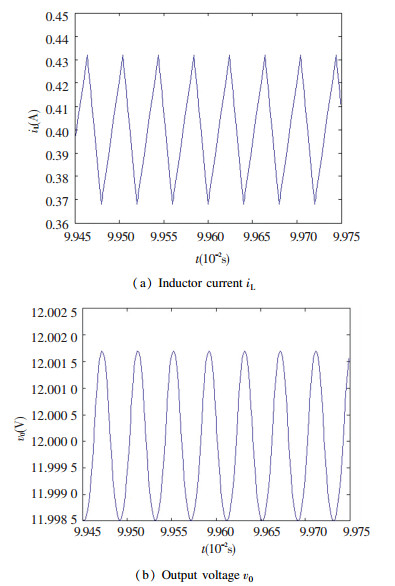
When α=1, β=1, the time domain waveforms are shown in Fig. 6. Clearly, the Buck converter operates in CCM. The experimental and theoretical values of integer order model are shown in Table 2. It can be found that results of numerical simulation are equal to the theoretical analysis, so the correctness of the theoretical analysis is verified.
|
Fig.6 The waveform of integral order Buck converter |
| Table 2 Results of integer order Buck converter |
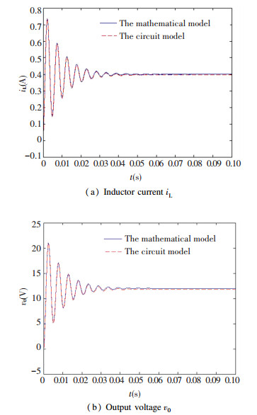
The comparison between the mathematical model and the circuit model is also given in Fig. 7. The experimental result of the circuit model is almost the same as the numerical simulation, therefore the theoretical analysis is correct.
|
Fig.7 Comparison results of integer order mathematical model and circuit model |
It can be obtained that ripples, the time of rise, the time of delay, the time of adjustment, the peak time and the overshoot in the dynamic response have changed greatly by comparing Fig. 5 and Fig. 7. The influence of the fractional order on the converter is obvious, so that the order should be considered as an extra parameter. This shows that if the integer order model is used to describe the converter approximately, an erroneous result will be obtained. In order to describe real dynamics characteristics of the Buck converter in CCM, a fractional order model should be used according to the fact that actual inductor and actual capacitor are both actually fractional.
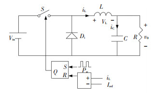
4.3 Dynamic AnalysisSome dynamic behaviors of the current-controlled Buck converter will be analyzed. The purpose of this part is to discuss the effect of the fractional order α and β on dynamic behavior. The circuit model is shown in Fig. 8.
|
Fig.8 The current-controlled Buck converter |
Reference current Iref and input voltage vin are used as the bifurcation parameter. Simulation parameters are as follows: vin=3.3 V, L=4.7 μH, C=10 μF, R=1.2 Ω, d=0.6, f = 1 000 kHz. When α=1 and β=1, the bifurcation diagram with reference current Iref of integer order model is shown in Fig. 9(a). When α=0.8 and β=0.8, the bifurcation diagram with reference current Iref of fractional order model is shown in Fig. 9(b).
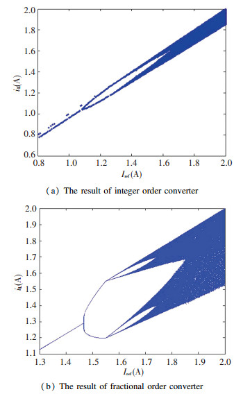
|
Fig.9 Bifurcation diagrams for varying Iref |
As shown in Fig. 9 (a) and the related enlarged diagrams in Fig. 10 (a): when Iref < 1.1 A, the converter operates in a stable period-1 state; when Iref=1.1 A, bifurcation occurs and the converter operates in period-2 state; until Iref=1.35 A and increase Iref, the converter gradually enter chaotic state. As shown in Fig. 9 (b) and the related enlarged diagrams in Fig. 10 (b): when Iref < 1.47 A, the converter operates in a stable period-1 state; when Iref=1.47 A, bifurcation occurs and the converter operates in period-2 state; when Iref= 1.55 A, the converter operates in period-4 state; until Iref=1.6 A and increase Iref, the converter gradually enter chaotic state.
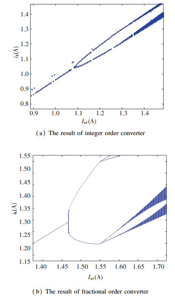
|
Fig.10 The enlarged diagram of Fig. 9 |
When Iref= 1 A, the bifurcation diagrams with the input voltage vin are shown in Fig. 11.
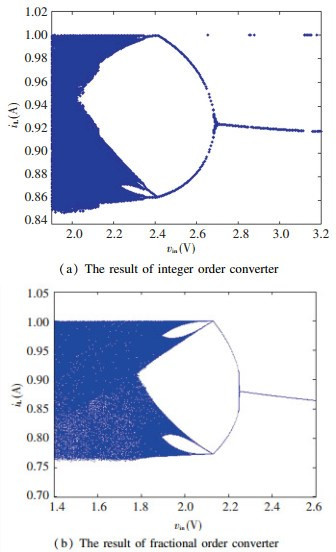
|
Fig.11 Bifurcation diagrams for varying vin |
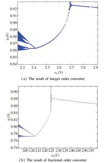
As shown in Fig. 11(a) and the related enlarged diagrams in Fig. 12(a): the converter initially operates in a chaotic state, when vin=2.35 V, the converter enters the period-3 state; when vin=2.4 V, inverse bifurcation occurs and the converter operates in period-2 state; when vin=2.7 V, inverse bifurcation occurs again and the converter operates in a stable period-1 state. As shown in Fig. 11 (b) and the related enlarged diagrams in Fig. 12 (b): the converter initially operates in a chaotic state, when vin=2.08 V, the converter enters the period-4 state; when vin=2.13 V, inverse bifurcation occurs and the converter operates in period-2 state; when vin=2.25 V, inverse bifurcation occurs again and the converter operates in a stable period-1 state.
|
Fig.12 The enlarged diagram of Fig. 11 |
From the above results, they all go through double period bifurcation, finally resulting in chaos for varying Iref whether the fractional order or the integer order converter. However, they have different routes to chaos and bifurcation points are moved backward when α and β vary. For the input voltage vin, their chaotic paths are almost identical, but bifurcation points are moved forward as α and β varies. The fractional order is the direct cause of the difference in dynamic behavior.
5 ConclusionsThe fractional order model can really reflect the real situation of Buck converter. The mathematical and state-space averaging models of fractional order Buck converter in CCM is established based on fractional calculus in this paper. The parameter condition that ensures the converter work in CCM and the transfer functions are given through theoretical analysis. Then numerical simulation results and circuit experimental results are compared, and the correctness of theoretical analysis is verified. Finally, its some dynamic behaviors are analyzed. Theoretical analysis and experimental results show that the inductor current, output voltage, ripples, the time of rise, the time of delay, the time of adjustment, the peak time, the overshoot and transfer functions are all affected by the fractional order, so the fractional order should be considered as an extra parameter. According to dynamic analysis, the bifurcation point will be changed and the converter has different chaotic paths as the order varying.
| [1] |
Kazimierczuk M K. Pulse-width Modulated DC-DC Power Converters. London: John Wiley and Sons, 2012. DOI:10.1002/9780470694640.ch3
(  0) 0) |
| [2] |
Zhang Weiping. Modeling and Control of Switching Converter. Beijing: China Electric Power Press, 2006: 64-78.
(  0) 0) |
| [3] |
Gurbina M, Lascu D. Stability aspects in one-cycle controlled buck converters. Advances in Electrical and Computer Engineering, 2014, 14(1): 43-48. DOI:10.4316/AECE.2014.01007 (  0) 0) |
| [4] |
Babaei E, Mahery H M. Mathematical modelling and analysis of transient and steady states of buck dc-dc converter in DCM. International Journal of Computational Fluid Dynamics, 2013, 32(1): 337-363. DOI:10.1108/03321641311293920 (  0) 0) |
| [5] |
Cliquennois S. Closed-loop sampled-data error model for PWM DC/DC converters with input variations. 2010 IEEE 12th Workshop on Control & Modeling for Power Electronics. Pisacataway: IEEE, 2010.1-4. DOI: 10.1109/COMPEL.2010.5562363.
(  0) 0) |
| [6] |
Janke W, Walczak M. Comparison of transient states in step-down power converter (BUCK) in continuous and discontinuous conduction mode. Bulletin of the Polish Academy of Sciences Technical Sciences, 2014, 62(4): 773-778. DOI:10.2478/bpasts-2014-0084 (  0) 0) |
| [7] |
Fang Chung-Chieh. Unified discrete-time modeling of buck converter in discontinuous mode. IEEE Transactions on Power Electronics, 2011, 26(8): 2335-2342. DOI:10.1109/TPEL.2010.2096517 (  0) 0) |
| [8] |
Maity S, Tripathy D, Bhattacharya T K, et al. Bifurcation analysis of PWM-1 voltage-mode-controlled buck converter using the exact discrete model. IEEE Transactions on Circuits & Systems I Regular Papers, 2007, 54(5): 1120-1130. DOI:10.1109/TCSI.2007.895526 (  0) 0) |
| [9] |
Revathi V M, Balasubramaniam P, Ratnavelu K. Delay-dependent H∞ filtering for complex dynamical networks with time-varying delays in nonlinear function and network couplings. Signal Processing, 2016, 118(C): 122-132. DOI:10.1016/j.sigpro.2015.06.017 (  0) 0) |
| [10] |
Sahabi M E, Li Guipu, Wang Xiangyu, et al. Disturbance compensation based finite-time tracking control of rigid manipulator. Mathematical Problems in Engineering, 2016, 2016(2): 1-12. DOI:10.1155/2016/2034795 (  0) 0) |
| [11] |
Zheng Chengde, Zhang Xiaoyu, Wang Zhanshan. Mode and delay-dependent stochastic stability conditions of fuzzy neural networks with Markovian jump parameters. Neural Processing Letters, 2016, 43(1): 195-217. DOI:10.1007/s11063-015-9413-x (  0) 0) |
| [12] |
Ahmed E, Elgazzar A S. On fractional order differential equations model for nonlocal epidemics. Physica A:Statistical Mechanics & its Applications, 2007, 379(2): 607-614. DOI:10.1016/j.physa.2007.01.010 (  0) 0) |
| [13] |
Ni Junkang, Liu Ling, Liu Chongxin, et al. Fractional order fixed-time nonsingular terminal sliding mode synchronization and control of fractional order chaotic systems. Nonlinear Dynamics, 2017, 89(3): 2065-2083. DOI:10.1007/s11071-017-3570-6 (  0) 0) |
| [14] |
Kingni S T, Pham V T, Jafari S, et al. Three-dimensional chaotic autonomous system with a circular equilibrium: Analysis, circuit implementation and its fractional-order form. Circuits Systems & Signal Processing, 2016, 35(6): 1933-1948. DOI:10.1007/s00034-016-0259-x (  0) 0) |
| [15] |
Westerlund S, Ekstam L. Capacitor theory. IEEE Transactions on Dielectrics & Electrical Insulation, 2002, 1(5): 826-839. DOI:10.1109/94.326654 (  0) 0) |
| [16] |
Westerlund S. Dead Matter Has Memory. Sweden: Causal Consulting, 2002: 90-111. DOI:10.1088/0031-8949/43/2/011
(  0) 0) |
| [17] |
Jonscher A K. Dielectric Relaxation In Solids. Xi'an: Xi'an Jiaotong University Press, 2008: 57-70. DOI:10.1088/0022-3727/32/14/201
(  0) 0) |
| [18] |
Petras I. A note on the fractional-order Chua's system. Chaos Solitons & Fractals, 2008, 38(1): 140-147. DOI:10.1016/j.chaos.2006.10.054 (  0) 0) |
| [19] |
Jesus I S, Tenreiro Machado A T. Development of fractional order capacitors based on electrolyte processes. Nonlinear Dynamics, 2009, 56(1-2): 45-55. DOI:10.1007/s11071-008-9377-8 (  0) 0) |
| [20] |
Tenreiro Machado A T, Galhano A M S F. Fractional order inductive phenomena based on the skin effect. Nonlinear Dynamics, 2012, 68(1-2): 107-115. DOI:10.1007/s11071-011-0207-z (  0) 0) |
| [21] |
Petras I. Fractional-Order Nonlinear Systems: Modeling, Analysis and Simulation. Berlin: Springer, 2011: 341-356. DOI:10.1007/978-3-642-18101-6
(  0) 0) |
| [22] |
Yang Ningning, Wu Chaojun, Jia Rong, et al. Modeling and characteristics analysis for a buck-boost converter in pseudo-continuous conduction mode based on fractional calculus. Mathematical Problems in Engineering, 2016, 2016(1): 1-11. DOI:10.1155/2016/6835910 (  0) 0) |
| [23] |
Wu Chaojun, Si Gangquan, Zhang Yanbin, et al. The fractional-order state-space averaging modeling of the Buck-Boost DC/DC converter in discontinuous conduction mode and the performance analysis. Nonlinear Dynamics, 2015, 79(1): 689-703. DOI:10.1007/s11071-014-1695-4 (  0) 0) |
| [24] |
Wang Faqiang, Ma Xikui. Fractional order Buck-Boost converter in CCM: modelling, analysis and simulations. International Journal of Electronics, 2014, 101(12): 1671-1682. DOI:10.1080/00207217.2014.888779 (  0) 0) |
| [25] |
Tan Cheng, Liang Zhishan. Modeling and performance analysis of the fractional order quadratic Boost converter in discontinuous conduction mode-discontinuous conduction mode. 2015 IEEE 10th Conference on Industrial Electronics and Applications (ICIEA). Piscataway: IEEE, 2015.724-729. DOI: 10.1109/ICIEA.2015.7334203
(  0) 0) |
| [26] |
Tan Cheng, Liang Zhishan. Modeling and simulation analysis of fractional-order Boost converter in pseudo-continuous conduction mode. Acta Physica Sinica, 2014, 63(7): 070502. (in Chinese) DOI:10.7498/aps.63.070502.(inChinese) (  0) 0) |
| [27] |
Wang Faqiang, Ma Xikui. Fractional order modeling and simulation analysis of Boost converter in continuous conduction mode operation. Acta Physica Sinica, 2011, 60(7): 7. (in Chinese) (  0) 0) |
| [28] |
Hartley T T, Lorenzo C F. The error incurred in using the caputo-derivative laplace-transform. Proceedings of the ASME International Design Engineering Technical Conferences and Computers and Information in Engineering Conference. San Diego, 2009.271-278. DOI: 10.1115/DETC2009-87648.
(  0) 0) |
| [29] |
Hartley T T, Trigeassou J C, Lorenzo C F, et al. Energy storage and loss in fractional-order circuit elements. Journal of Computational Nonlinear Dynamics, 2015, 10(6): 061006. DOI:10.1115/1.4029511 (  0) 0) |
 2019, Vol. 26


