In 1971, Professor Chua of University of California at Berkeley[1] predicted the existence of a new circuit device describing the relationship between charge and magnetic flux in theory, and defined such circuit device as memristor. In 2008, Hewlett-Packard laboratories realized this memristor device with TiO2[2]. Currently, there are three classical models: HP memristor model[2], cubic charge controlled memristor model[3], and cubic magnetic controlled memristor model[4-5]. Many researchers have analyzed the equivalent circuit of each model[6-7] and found the applications of the memristor in many fields[8-11]. In the analysis of the memristive characteristic curve, researchers have analyzed the influence of the external parameters on the memristor curve[12-17]. However, no researcher has analyzed the initial phase property of the input signal and compared the merits and demerits of the three models yet. Therefore, in this paper we changed the parameters of external signal and analyzed the influence on each model by observing the memristive characteristic curve in order to find the model with the best anti-interference capability.
In the first part, we input the signals with different initial phases to the three models to find the model which has the best adaptation to the external signal. In the second part, we input the same external excitation and noise to the three models to analyze the noise resistance of them. In the last part, we changed the quantity of the signals input in the three models respectively to analyze the precision of these models.
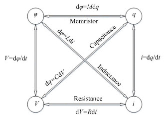
2 Three Classical Models of MemristorMemristor is the fourth basic passive device after the resistance, the capacitance, and the inductance. The definition of the basic passive devices is based on four basic states: charge, magnetic flux, voltage, and current. The relationship of the four states is shown in Fig. 1.
|
Fig.1 The basic states of the circuit and their relations |
| $ {\rm{d}}\varphi = M{\rm{d}}q $ | (1) |
or
| $ {\rm{d}}q = W{\rm{d}}\varphi $ | (2) |
where M is the memristance and W is the memductance. Eq. (1) is the definition of the new basic passive device which is called memristor. The relationship of the V, I, q and φ gets complete because any two states can be connected by one equation now.
Memristive system controlled by an n-dimensional state variable x is called generalized memristor. Its definition is
| $ y = g(x,u)u $ | (3) |
| $ \frac{{{\rm{d}}x}}{{{\rm{d}}t}} = f(x,u) $ | (4) |
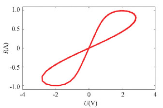
where g(x, u) is a piecewise continuous function and g(x, 0)≠0. y and u are the variables of the circuit. Its characteristic curve is shown in Fig. 2.
|
Fig.2 The pinched hysteresis loop |
The memristive device has three properties[6]: 1) The Ⅰ-Ⅴ curve is a pinched hysteresis loop; 2) When the frequency of the input signal tends to ∞, the Ⅰ-Ⅴ curve degenerates into a straight line; 3) The area of the magnetic hysteresis sidelobe will decrease with the increasing of frequency.
The first model is HP memristor (HPM) model[2]. It can be described by Fig. 3 and Eqs.(5)-(8):

|
Fig.3 HP memristor model |
| $ {R_m}(t) = {R_{{\rm{off}}}} + \left( {{R_{{\rm{on}}}} - {R_{{\rm{off}}}}} \right)\frac{{w(t)}}{D} $ | (5) |
| $ V = {R_{{\rm{mem}}}} \cdot I(t) $ | (6) |
| $ \frac{{{\rm{d}}x}}{{{\rm{d}}t}} = k \cdot i(t) \cdot f(x),k = \frac{{{\mu _v}{R_{{\rm{on}}}}}}{{{D^2}}} $ | (7) |
| $ x = \frac{W}{D} \in (0,1) $ | (8) |
where D is the thickness of TiO2 thin film, Ron is the lower resistance which is dozens of ohms, Roff is the higher resistance which is hundreds of times of the lower resistance, and x is the internal state variable of the memristor, namely, the ratio of the doped region's thickness to the total thickness.
Another model is the cubic charge controlled memristor (CCM) model. This model is described by a smooth continuous nonlinear cubic function as follows:
| $ \varphi = aq + b{q^3} $ | (9) |
| $ M(q) = a + 3b{q^3} $ | (10) |
| $ \frac{{{\rm{d}}q}}{{{\rm{d}}t}} = i $ | (11) |
| $ u = M(q) \cdot i $ | (12) |
where M is the memristance, q is the charge, and φ is the magnetic flux.
The third model is the cubic magnetic controlled memristor (CMM) model. This model is described by a smooth continuous nonlinear cubic function as follows:
| $ q = a\varphi + b{\varphi ^3} $ | (13) |
| $ W(\varphi ) = a + 3b{\varphi ^2} $ | (14) |
| $ \frac{{{\rm{d}}\varphi }}{{{\rm{d}}t}} = u $ | (15) |
| $ i = W(\varphi ) \cdot V $ | (16) |
where W is the memductance, q is the charge, and φ is the magnetic flux.
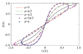
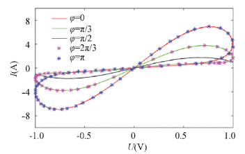
3 Anti-Interference Capability of the Three Types of Classical Models 3.1 Effect of the Initial Phase on Each ModelWe find that different models showed different results when signals with different initial phases were input. We input the signal V=A sin(ωt+φ) and changed the initial phase gradually to observe the variation on Ⅰ-Ⅴ curves of the different memristor models described above. We can get the following Ⅰ-Ⅴ curve of different models (Figs. 4-5).
|
Fig.4 The initial phase's effect on the CCM model (a=b=1, i.e., φ=q+q3; voltage amplitude A=1, frequency ω=1) |
|
Fig.5 The initial phase's effect on the CMM model (a=1, b=1, i.e., q=φ+φ3; voltage amplitude A=1, angular frequency ω=1) |
As shown in Figs. 4-5, when the initial phase increased from 0 to π/2, the curve gradually degenerated, and the pinched loop got closer until the initial phase was π/2. Then it degenerated into a single curve, and its memristive properties disappeared. At this time, the memristor degenerated into a normal resistor. When the initial phase increased from π/2 to π, the loop got separated gradually, and the pinched loop reappeared and displayed the memristive properties again.
According to the curve, we can observe that the curve is exactly the same when the initial phase is symmetric to π/2. It shows that the initial phase of the input signal affected the memristive properties of both the CCM model and CMM model. As the initial phase of the input signal increased to π/2, it degenerates into a single curve.
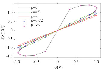
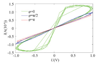
As shown in Fig. 6, there was no degeneration when the initial phase was π/2, and the two lines of the magnetic hysteresis loop were gradually approaching when initial phase increased from 0 to π. The memristor still maintained its memristive properties and the magnetic hysteresis loop still existed. Moreover, Fig. 7 shows that the Ⅰ-Ⅴ curve tended to idealize from the initial incompletely ideal situation caused by the noise when initial phase increased from 0 to π. It can be observed that the initial phase of the input signal satisfies the following rule: the smaller '|φ-π|' is, the easier it is for the hysteresis loop to become idealized. Therefore, the variation on the initial phase of the input signal does not make the memristive features disappear.
|
Fig.6 The initial phase effect on the HPM model (Ron=100 Ω, Roff=16 kΩ, x0=0.3, D=10 nm, μv=10-14m2/(s·V), and f(x)=1, voltage amplitude A=1, angular frequency ω=π) |
|
Fig.7 The initial phase's effect on the HPM model when the magnetic hysteresis loop is not idealized |
The experiment and simulation above show that when changing the initial phase of the external signal, the HPM model will not degenerate while the CCM model and CMM model will degenerate.
Therefore, we can conclude that the HPM model has the best adaptability to the change of external signal, and its memristive features will not disappear due to the variation of the external signal. Furthermore, the HPM model also has some anti-interference capability to noise since there is no degeneration.
3.2 Analyses on the Three Models with Several Superimposed SignalsWe added four sinusoidal signals whose initial phases were 0, π/4, π/3, π/2 respectively as shown in Table 1 and kept the other parameters the same to get the signals shown in Table 2.
| Table 1 Four signals with different initial phases |
| Table 2 Addition of these four signals in order |
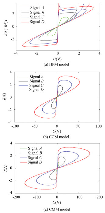
In other word, by changing the quantity of the input signals, we can observe the Ⅰ-Ⅴ curve of each model, as shown in Fig. 8.
|
Fig.8 Simulation of each model when several signals are input |
Pinched loops of different models are shown in the figures above. When we focused on the coordinate axis of the curves of the CCM/CMM model carefully, we found that the value of X-axis had a large variation when the quantity of the input signal was increased, which means the precision of the memristor model with several input signals became lower than that of the model with only one input signal. The influence of the signals' quantity is shown in Table 3. We can find that the amplitude of the signal increased about twenty times in the CCM and CMM models while the amplitude of the signal only increased about two times in HPM model. Therefore, the HPM model can maintain precision better than the other two models when several signals or some noise are input.
| Table 3 The influence of each model with several input signals |
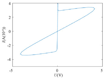
Increasing the quantity of the input signal added to the HPM model to 8, we got the following curve, as shown in Fig. 9. It shows that the amplitude only increased about three times and the precision was still acceptable.
|
Fig.9 Ⅰ-Ⅴ curve when eight signals are input |
Therefore, we can draw the conclusion that the HPM model can maintain precision better than the other two models.
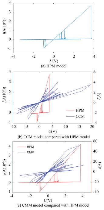
3.3 Analyses on the White NoiseBase on the analyses above, we tested the anti-interference capability of memristor models. To find the model with the best anti-interference capability, we input white noise in each model because it is more universal, then we got the Ⅰ-Ⅴ curves of each model in Fig. 10.
|
Fig.10 Influence of white noise on each model |
Fig. 10 shows that both the CCM model and CMM model have the irregular characteristic curves while the curve of HPM model is still a pinched hysteresis loop, thus we can draw the conclusion: when the noise exists, HPM model still has memristive properties while the CCM and the CMM models have lost the memristive properties.
We analyzed the reasons that makes pinched hysteresis loop of the CCM/CMM models turn irregular. Firstly, the curves drawn by the simulation software were pinched in every single time. However, the signal with the initial phase of π/2 led to a different degree of degeneracy of each curve, so the overall view was irregular. Secondly, the white noise can be considered as the sum of many signals with different initial phases. In Section 3.2, we have found that only the HPM model kept the precision when we increased the quantity of the input signals. The precision of CCM and CMM models had a large variation. Based on these two reasons, the anti-interference capability of the CCM and CMM models are not good enough. But the HPM model could still exhibit the memristive properties and pinched hysteresis loop was obviously under the noise condition. So HPM model might be a better choice for the realization of memristor.
It is also important to note that the model shows the memristive properties on a larger scale while it shows an irregular curve on its original scale after noise is added to the HPM model.
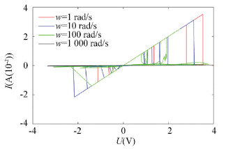
To verify that the HPM model is still a memristor model under the noise condition, we changed the frequency of the input sinusoidal signal to observe the frequency influence.
As shown in Fig. 11, it can be found that when the frequency of the signal is high enough, it will degenerate into a straight line. The maximum frequency leading to the degeneration with noise mixed was higher than the maximum frequency with only one signal, which means the HPM model can keep the memristive properties in the case of noise.
|
Fig.11 The frequency degeneration of the HPM model when the noise exists |
4 Conclusions
This study finds a certain reference to the selection of the better memristor model when realizing the theoretical memristor model. We compared anti-interference capability of the three different classical models and found the best model. Moreover, we discussed the reasons that caused the differences. The following conclusions can be drawn:
1) When the signals with different initial phases were input, there was degeneration in the CCM model and the CMM model, but no degeneration phenomenon appeared in the HPM model.
2) When multiple signals were input, the HPM memristor model could basically maintain the original precision. However, the precision of the CCM model and CMM model would change obviously.
3) Based on the two points above, the HP memristor model has a better anti-interference capability to the noise compared with the CCM and CMM models.
In conclusion, the HPM model is superior to the CCM model and CMM model in the realization of the memristor. When new models appear, it is beneficial to find a better model by using such an anti-interference analysis.
| [1] |
Chua L O. Memristor-The missing circuit element. IEEE Transactions on Circuit Theory, 1971, 18(5): 507-519. DOI:10.1109/tct.1971.1083337 (  0) 0) |
| [2] |
Strukov D B, Snider G S, Stewart D R, et al. The missing memristor found. Nature, 2008, 453: 80-83. DOI:10.1038/nature08166 (  0) 0) |
| [3] |
Hu F W, Bao B C B, Wu H G, et al. Equivalent circuit analysis model of charge-controlled memristor and its circuit characteristics. Acta Physica Sinica Chinese Edition, 2013, 62(21): 218401-1-218401-8. DOI:10.7498/aps.62.218401 (  0) 0) |
| [4] |
Bao B C, Xu J P, Zhou G H, et al. Chaotic memristive circuit: Equivalent circuit realization and dynamical analysis. Chinese Physics B, 2011, 20(12): 120502-1-120502-7. DOI:10.1088/1674-1056/20/12/120502 (  0) 0) |
| [5] |
Bao B C, Liu Z, Xu J P. Transient chaos in smooth memristor oscillator. Chinese Physics B, 2010, 19(3): 03510-1-03510-6. DOI:10.1088/1674-1056/19/3/030510 (  0) 0) |
| [6] |
Hu F W, Bao B C, Wu H G, et al. Equivalent circuit analysis model of charge-controlled memristor and its circuit characteristics. Acta Physica Sinica, 2013, 62(21): 218401-1-218401-18. DOI:10.7498/aps.62.218401 (  0) 0) |
| [7] |
Yang L, Pu Z Z, Huang L, et al. Active flux-controlled memristor emulator and the frequency response analysis of memristor based filter. Electronic Components and Materials, 2015, 34(7): 5-10. DOI:10.14106/j.cnki.1001-2028.2015.07.002 (  0) 0) |
| [8] |
Duan S K, Hu X F, Wang L D, et al. Memristor-based RRAM with applications. Science China (Information Sciences), 2012, 55(6): 1446-1460. DOI:10.1007/s11432-012-4572-0 (  0) 0) |
| [9] |
Li C D, Ge J H, Tian Y. Associative learning of memristive synapses circuits based on spiking neural networks. Journal of Chongqing University, 2014, 37(7): 115-124. DOI:10.11835/j.issn.1000-582X.2014.07.016 (  0) 0) |
| [10] |
Yang F G, Hu W P. Gradual resistance tuning of a metal-organic framework nanocrystals flexible memristor towards biology synapses applications. Proceedings of the 6th International Conference on Nanoscience & Technology, 2015. Paris:Atlantis Press.2015.
(  0) 0) |
| [11] |
Yuan Z S, Li H T, Zhu X H. A digital-analog hybrid random number generator based on memristor. Acta Physica Sinica, 2015, 64(24): 240503-1. DOI:10.7498/aps.64.240503 (  0) 0) |
| [12] |
Adhikari S P, Sah M P, Kim H, et al. Three fingerprints of memristor. IEEE Transactions on Circuits and Systems Ⅰ: Regular Papers, 2013, 60(11): 3008-3021. DOI:10.1109/TCSI.2013.2256171 (  0) 0) |
| [13] |
Su D T, Sun Y Z, Yang H B. Analysis on influence parameter of memristance. Transducer and Microsystem Technologies, 2017, 36(12): 43-45,49. DOI:10.13873/J.1000-9787(2017)12-0043-03 (  0) 0) |
| [14] |
Cao Y J, Ye S, Hu C X. Characteristics of Chua's circuit based on memristor and responses to stimulating signals. Proceedings of 2016 5th International Conference on Environment, Materials, Chemistry and Power Electronics (EMCPE 2016). Paris: Atlantis Press, 2016: 183-186. DOI:10.2991/emcpe-16.2016.39
(  0) 0) |
| [15] |
Guo Y Q, Duan S K, Wang L D. Influence of length parameter on the characteristics of nanoscale titanium oxide memristor. Acta Physica Sinica, 2015, 64(10): 108502-1. DOI:10.7498/aps.64.108502 (  0) 0) |
| [16] |
Dongale T D, Patil K P, Mullani S B, et al. Investigation of process parameter variation in the memristor based resistive random access memory (RRAM): Effect of device size variations. Materials Science in Semiconductor Processing, 2015, 35: 174-180. DOI:10.1016/j.mssp.2015.03.015 (  0) 0) |
| [17] |
Zhu Z M, Wang Y H. Device modeling and parameter analysis of passive electronic component of the memristor. Electronic Components and Materials, 2014, 33(8): 62-65. DOI:10.3969/j.issn.1001-2028.2014.08.016 (  0) 0) |
 2019, Vol. 26


