Due to the need to augment traffic capacity in urban highways, more and more curved bridges have been constructed around the word. As a type of thin-walled structures, the bridge web is likely to fail due to shear buckling or yielding. Therefore, the shear buckling of bridge webs is one of the most important aspects in the design of composite girder bridges and steel girder bridges. However, the calculation for shear buckling of curved bridge webs generally uses the equations for straight bridge webs or just introduces a modification factor for bridge design. Due to the curvature, the shear behaviors of curved bridge webs are quite different from those of straight bridge webs, thus a more accurate estimate for shear buckling stress of curved bridge webs is desirable.
Early research on the elastic shear buckling of curved plates was conducted by Leggett[1] in 1937. However, only long panels were considered in this study. Later on, Batdorf et al. [2-3] studied the elastic stability of curved rectangular panels in 1947. Stein et al. [4-5] studied the shear buckling stress of infinitely long panels and curved panels with stiffeners in 1949. Mariani[6] studied the shear behaviors of curved plates with multiple stiffeners. Elgaaly[7] suggested the formulas for shear buckling strength of girders with corrugated steel webs. Lee [8] suggested that the equations for straight girders proposed by Lee [9-10] could effectively estimate the shear buckling stress of curved panels. However, the results lack theoretical support. Davidson et al. [11] theoretically and numerically studied the buckling behaviors of curved girder webs subjected to combined bending and shear. Kim et al. [12] numerically studied the behaviors of transverse stiffeners in curved girders and proposed the recommendations for design of stiffeners in curved girders. Lee et al. [13] numerically studied the elastic shear buckling coefficients of curved girder webs and proposed a simple design equation. Nakai et al. [14] conducted collapse tests of curved girders under combined bending and shear. Machaly et al. [15] numerically studied the effect of curvature on elastic buckling shear strength. The analysis revealed that the critical buckling load of horizontally curved web plates may exceed that of an identical straight web panel by more than 10%. A new set of design rules were proposed by introducing an amplification factor to the web buckling coefficient of straight girders to account for the effect of horizontal curvature. Keerthan[16] experimentally studied the shear stress of litesteel girders with web openings. Bogaert [17] numerically studied the buckling stress of curved bridge webs considering residual stress. Compared with flat webs, curved webs had a larger shear failure load. It was conservative to treat the curved webs as straight webs. Abu-Hamd et al. [18] numerically studied the buckling stress of tapered girders subjected to combined shear and bending. Empirical approximate formulas were proposed to predict the flexure-shear buckling load of tapered girders. Staen et al. [19] experimentally and numerically studied the buckling of curved web close steel section. The elastic buckling load was increasing with increasing curvature for both the experimental and numerical approach. Martins et al. [20] presented a detailed review of behaviors of thin-walled curved steel panels subject to shear stresses.
From the above research work, it is generally recognized that the elastic shear buckling load of curved panels is greater than that of straight panels. However, there is no precise formula for elastic shear buckling stress of curved bridge webs. In this paper, the curved bridge web is equivalent to an isotropic cylindrical flat shell, and the analytical formula for elastic shear buckling stress of curved bridge webs is deduced by means of the Galerkin method.
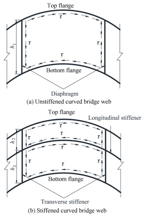
2 Instability Modes of Curved Bridge WebsFor curved composite bridges or curved steel bridges, there are unstiffened webs and stiffened webs. An unstiffened web can be treated as an isotropic shell constricted by flanges and diaphragms to analyze the shear buckling in curved girders (see Fig. 1(a)).
|
Fig.1 Curved bridge webs under pure shear |
There are two possible buckling modes of stiffened webs. If the rigidity of stiffeners is relatively low, the out-plane deflection occurs in the stiffeners, thus they play a role in enhancing the out-plane stiffness of the webs. If the rigidity of stiffeners is relatively large, the out-plane deflection does not occur in the stiffeners, thus they play a role in supporting the webs. For the latter, the region bounded by stiffeners or flanges can be treated as an isotropic shell to analyze the shear buckling in curved girders (see Fig. 1(b)) [21].
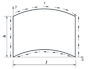
According to the theory of plate and shell, if the ratio of a shell's height to its short side is less than 0.2, the shell can be analyzed as a shallow shell. For curved girder bridges with vertical steel webs, webs always meet the conditions above. So an unstiffened curved web or the later stiffened curved web can be treated as an isotropic cylinder shallow shell (see Fig. 2) for the shear buckling analysis.
|
Fig.2 Equivalent isotropic cylinder shallow shell |
3 Critical Buckling Stress under Pure Shear
According to the stability theory of plate and shell, the equilibrium equation in the normal direction and the deformation compatibility equation of the equivalent isotropic shallow shell can be expressed respectively as [22]:
| $ \begin{array}{*{20}{c}} {\frac{D}{t}\left( {\frac{{{\partial ^4}}}{{\partial {x^4}}} + \frac{{{\partial ^4}}}{{\partial {x^2}\partial {y^2}}} + \frac{{{\partial ^4}}}{{\partial {y^4}}}} \right)w + \left( {{k_x}\frac{{{\partial ^2}}}{{\partial {y^2}}} - 2{k_{xy}}\frac{{{\partial ^2}}}{{\partial x\partial y}} + } \right.}\\ {\left. {{k_y}\frac{{{\partial ^2}}}{{\partial {x^2}}}} \right)\mathit{\Phi } = {\sigma _x}\frac{{{\partial ^2}w}}{{\partial {x^2}}} + 2\tau \frac{{{\partial ^2}w}}{{\partial x\partial y}} + {\sigma _y}\frac{{{\partial ^2}w}}{{\partial {y^2}}}} \end{array} $ | (1) |
| $ \begin{array}{l} \frac{1}{E}\left[ {\frac{{{\partial ^4}}}{{\partial {x^4}}} + \frac{{{\partial ^4}}}{{\partial {x^2}\partial {y^2}}} + \frac{{{\partial ^4}}}{{\partial {y^4}}}} \right]\mathit{\Phi } - \\ \;\;\;\;\;\;\;\;\left( {{k_x}\frac{{{\partial ^2}}}{{\partial {y^2}}} - 2{k_{xy}}\frac{{{\partial ^2}}}{{\partial x\partial y}} + {k_y}\frac{{{\partial ^2}}}{{\partial {x^2}}}} \right)w = 0 \end{array} $ | (2) |
where E is the Young's modulus; D is the bending rigidity; Φ is the stress function; w is the deflection of the shell; t is the thickness; R is the curvature radius; kx and ky are the curvatures along the axis x and y; kxy is the torsional curvature, for cylinder shallow shell, kx=1/R, ky=kxy=0; σx and σy are the normal stress; τ is the shear stress. When the equivalent isotropic shallow shell under pure shear force, σx=σy=0, Eq. (1) and Eq. (2) can be simplified as:
| $ \begin{array}{l} \frac{D}{t}\left( {\frac{{{\partial ^4}}}{{\partial {x^4}}} + 2\frac{{{\partial ^4}}}{{\partial {x^2}\partial {y^2}}} + \frac{{{\partial ^4}}}{{\partial {y^4}}}} \right)w + \frac{1}{R}\frac{{{\partial ^2}\mathit{\Phi }}}{{\partial {y^2}}} = \\ \;\;\;2\tau \frac{{{\partial ^2}w}}{{\partial x\partial y}} \end{array} $ | (3) |
| $ \frac{1}{E}\left( {\frac{{{\partial ^4}}}{{\partial {x^4}}} + 2\frac{{{\partial ^4}}}{{\partial {x^2}\partial {y^2}}} + \frac{{{\partial ^4}}}{{\partial {y^4}}}} \right)\mathit{\Phi } - \frac{1}{R}\frac{{{\partial ^2}w}}{{\partial {y^2}}} = 0 $ | (4) |
It can be conservatively assumed that curved bridge webs satisfy four-edge simply supported boundaries. The deflection function and stress function can be expressed respectively as:
| $ w = \sum\limits_{m = 1}^\infty {\sum\limits_{n = 1}^\infty {{A_{mn}}} } \sin \frac{{m{\rm{ \mathit{ π} }}x}}{l}\sin \frac{{n{\rm{ \mathit{ π} }}y}}{h} $ | (5) |
| $ \mathit{\Phi } = \sum\limits_{m = 1}^\infty {\sum\limits_{n = 1}^\infty {{B_{mn}}} } \sin \frac{{m{\rm{ \mathit{ π} }}x}}{l}\sin \frac{{n{\rm{ \mathit{ π} }}y}}{h} $ | (6) |
where h is the height of the region bounded by stiffeners or flanges, l is the length equal to the linear distance between the two adjacent diaphragms (or transverse stiffeners).
Substituting Eq. (5) and Eq.(6) into Eq. (4), Bmn can be expressed as:
| $ {B_{mn}} = - {A_{mn}}\frac{1}{{{{\rm{ \mathit{ π} }}^2}{h^2}R}}\frac{{E{n^2}}}{{{{\left( {\frac{{{m^2}}}{{{l^2}}} + \frac{{{n^2}}}{{{h^2}}}} \right)}^2}}} $ | (7) |
Substituting Eq. (7) into Eq. (6), the stress function Eq. (6) can be expressed as:
| $ \begin{array}{l} \mathit{\Phi } = - \frac{E}{{{{\rm{ \mathit{ π} }}^2}{h^2}R}} \cdot \\ \;\;\;\;\;\;\sum\limits_{m = 1}^\infty {\sum\limits_{n = 1}^\infty {{A_{mn}}} } \frac{{{n^2}}}{{{{\left( {\frac{{{m^2}}}{{{l^2}}} + \frac{{{n^2}}}{{{h^2}}}} \right)}^2}}}\sin \frac{{m{\rm{ \mathit{ π} }}x}}{l}\sin \frac{{n{\rm{ \mathit{ π} }}y}}{h} \end{array} $ | (8) |
Eq. (3) can be equivalent to Eq. (9) according to the Galerkin method.
| $ \begin{array}{l} \int_0^l {\int_0^h {\left[ {\frac{D}{t}\left( {\frac{{{\partial ^4}}}{{\partial {x^4}}} + 2\frac{{{\partial ^4}}}{{\partial {x^2}\partial {y^2}}} + \frac{{{\partial ^4}}}{{\partial {y^4}}}} \right)w + } \right.} } \\ \;\;\;\;\;\;\;\left. {\frac{1}{R}\frac{{{\partial ^2}\mathit{\Phi }}}{{\partial {y^2}}} - 2\tau \frac{{{\partial ^2}w}}{{\partial x\partial y}}} \right] \times \\ \;\;\;\;\;\;\;\sin \frac{{i{\rm{ \mathit{ π} }}x}}{l}\sin \frac{{j{\rm{ \mathit{ π} }}y}}{h}{\rm{d}}x{\rm{d}}y = 0 \end{array} $ | (9) |
Taking the integral characteristics of trigonometric functions:
| $ \begin{array}{l} \int_0^l {\sin } \frac{{m{\rm{ \mathit{ π} }}x}}{l}\cos \frac{{i{\rm{ \mathit{ π} }}x}}{l}{\rm{d}}x = \\ \;\;\;\left\{ {\begin{array}{*{20}{c}} {\frac{{2lm}}{{\left( {{m^2} - {i^2}} \right){\rm{ \mathit{ π} }}}},}&{m \pm i = {\rm{odd\;number}}}\\ {0,}&{m \pm i = {\rm{even\;number}}} \end{array}} \right. \end{array} $ | (10a) |
| $ \int_0^l {\sin } \frac{{m{\rm{ \mathit{ π} }}x}}{l}\sin \frac{{i{\rm{ \mathit{ π} }}x}}{l}{\rm{d}}x = \left\{ {\begin{array}{*{20}{l}} {\frac{l}{2},}&{m = i}\\ {0,}&{m \ne i} \end{array}} \right. $ | (10b) |
Eq. (9) can be simplified as:
| $ \begin{array}{l} \frac{{lh}}{4}{A_{mn}}\frac{{D{{\rm{ \mathit{ π} }}^4}}}{t}{\left( {\frac{{{m^2}}}{{{l^2}}} + \frac{{{n^2}}}{{{h^2}}}} \right)^2} + \frac{{lh}}{4}\frac{1}{{{h^4}{R^2}}}{A_{mn}} \cdot \\ \;\;\;\;\;\;\;\;\;\;\frac{{E{n^4}}}{{{{\left( {\frac{{{m^2}}}{{{l^2}}} + \frac{{{n^2}}}{{{h^2}}}} \right)}^2}}} - \\ \;\;\;\;\;\;\;\;8\tau \sum\limits_{i = 1}^\infty {\sum\limits_{j = 1}^\infty {{A_{ij}}} } \frac{{mnij}}{{\left( {{m^2} - {i^2}} \right)\left( {{n^2} - {j^2}} \right)}} = 0\\ \left( {m \pm i = {\rm{odd\;number, }}n \pm j = {\rm{odd\;number}}} \right) \end{array} $ | (11) |
given:
| $ \begin{array}{l} {C_{mn}} = \frac{{lh}}{{32mn}}\left[ {\frac{{D{{\rm{ \mathit{ π} }}^4}}}{t}{{\left( {\frac{{{m^2}}}{{{l^2}}} + \frac{{{n^2}}}{{{h^2}}}} \right)}^2} + } \right.\\ \;\;\;\;\left. {\frac{1}{{{h^4}{R^2}}}\frac{{E{n^4}}}{{{{\left( {\frac{{{m^2}}}{{{l^2}}} + \frac{{{n^2}}}{{{h^2}}}} \right)}^2}}}} \right] \end{array} $ | (12) |
and:
| $ \alpha = \frac{l}{h} $ | (13) |
Then Eq. (12) can be expressed as:
| $ \begin{array}{*{20}{c}} {{C_{mn}} = \frac{1}{{32mnt{h^2}}}\left[ {\frac{{{{\rm{ \mathit{ π} }}^4}D}}{{{\alpha ^3}}}{{\left( {{m^2} + {n^2}{\alpha ^2}} \right)}^2} + } \right.}\\ {\left. {\frac{{t{h^4}}}{{{R^2}}}\frac{{{\alpha ^5}{n^4}E}}{{{{\left( {{m^2} + {n^2}{\alpha ^2}} \right)}^2}}}} \right]} \end{array} $ | (14) |
According to D=(Et3)/(12(1-ν2)), where v is the Poisson's ratio, then Eq. (14) can be expressed as:
| $ \begin{array}{l} {C_{mn}} = \frac{D}{{32mnt{h^2}}}\left[ {\frac{{{{\rm{ \mathit{ π} }}^4}}}{{{\alpha ^3}}}{{\left( {{m^2} + {n^2}{\alpha ^2}} \right)}^2} + } \right.\\ \;\;\;\;\;\;\left. {\frac{{12\left( {1 - {\nu ^2}} \right){h^4}}}{{{R^2}{t^2}}}\frac{{{\alpha ^5}{n^4}}}{{{{\left( {{m^2} + {n^2}{\alpha ^2}} \right)}^2}}}} \right] \end{array} $ | (15) |
Eq. (11) can be further simplified as:
| $ \begin{array}{l} {C_{mn}}{A_{mn}} - \tau \sum\limits_i {\sum\limits_j {{A_{ij}}} } \frac{{ij}}{{\left( {{m^2} - {i^2}} \right)\left( {{n^2} - {j^2}} \right)}} = 0\\ \left( {m \pm i = {\rm{odd\;number, }}n \pm j = {\rm{odd\;number}}} \right) \end{array} $ | (16) |
Giving certain values to m and n in Eq. (16), a series of linear algebraic equations with Aij as unknowns can be obtained. Based on Eq. (16), assuming the coefficient determinant of the linear algebraic equations equals to zero, the elastic shear buckling strength of curved bridge webs (τce)can be derived and expressed as:
| $ \tau _c^e = {k_c}\frac{D}{{{h^2}t}} $ | (17) |
where kc is the shear buckling coefficient of curved bridge webs. kc values can be taken from Table 3 or Eq. (19). The detailed solution of kc is given below.
| Table 3 The shear buckling coefficient kc values (m=30, n=30) |
Theoretically, more numbers of trigonometric series (as shown in Eq. (5)), the more precise the solution is. If m and n increase toward infinity, the precise results can be obtained. However, the calculation effort increases with the increasing numbers of trigonometric series. By comparison of the trial results, desirable results can be obtained without too many numbers of trigonometric series. In the case of curved bridge webs with the length-height ratio l/h less than 5, the difference between the results with m=30, n=30 and the results with m=25, n=25 is less than 1%. m=30 and n=30 are adopted in the following calculation.
4 Calculations and Parameter Analysis of kc 4.1 Comparisons on Isotropic PlatesBased on "Theory of Elastic Stability"[23], the critical shear buckling strength of isotropic rectangular plates (τe)can be expressed as Eq.(18).
| $ {\tau ^e} = k\frac{{{{\rm{ \mathit{ π} }}^2}D}}{{{h^2}t}} $ | (18) |
where k is the elastic shear buckling coefficient of isotropic rectangular panels. The coefficient k for four-edge simply supported boundaries is given in Ref. [23].
When R increases toward infinity, the elastic shear buckling stress formula of curved bridge webs Eq. (17) derived in this paper can be also applied to isotropic plates. The shear buckling coefficient kc in Eq. (17) should divide by π2 to meet the needs of comparisons. The shear buckling coefficients k from Ref. [23] and kc/π2 derived in this paper are shown in Table 1.
| Table 1 Elastic shear buckling coefficient of isotropic rectangular plates for four-edge simply supported boundaries |
As shown in Table 1, the difference between kg/π2 from the formula derived in this paper and k from Ref.[23] is less than 1.5%. Thus, the accuracy of the solution method proposed in this paper is verified.
4.2 Calculations of kcIn Eq. (15), Cmn is associated with the length-height ratio l/h, and the expression h2/(Rt). In other words, the shear buckling coefficient kc is associated with the parameters above. The Poisson's ratio of steel is about 0.3, so v is taken as 0.3 in the hereafter calculation.
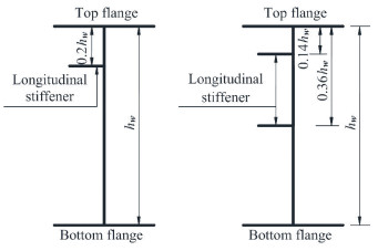
Table 2 gives height-thickness ratio hw/t in the specifications for bridge design. As can be seen from Table 2, height-thickness ratio hw/t in Chinese specification is larger than it in Japanese specification. For a conservative consideration, hw/t value is determined according to Chinese specification. Height-thickness ratio hw/t can increase up to 120% in Table 2. In the Chinese specifications for design of highway steel bridges [24], the locations of longitudinal stiffeners are given in Fig. 3. In Eq. (17), h is the height of the region bounded by stiffeners or flanges. According to Fig. 3 and Table 2, considering the amplification factor 1.2, the maximum h/t value is 269 for the web with transverse stiffeners and one longitudinal stiffener. For the available curved girder bridges, the web's height-length ratio hw/l generally ranges from 1/11 to 1/30, and the central angle l/R is generally no more than π/2. Because h does not exceed hw, when h equals to hw, hw /l equals to 1/11, and l/R equals to π/2, the upper limit of h/R of curved bridges does not exceed 0.143. Then the upper limit of h2/(Rt) of curved bridges does not exceed 39.
| Table 2 Height-thickness ratio hw/t |
|
Fig.3 The longitudinal stiffeners of bridges |
Table 3 lists the shear buckling coefficient kc values with the parameter h2/(Rt) ranges from 0 to 40, the aspect ratio l/h ranges from 1 to 5, and 900 triangular series items (m=30, n=30).
Through fitting the data in Table 3, the shear buckling coefficient kc can be calculated as:
| $ {k_c} = \left\{ \begin{array}{l} \left[ {1 + {\alpha ^{0.2}}\left( {0.015\beta + 0.0015{\beta ^2}} \right)} \right]{{\rm{ \mathsf{ π} }}^2}k,\\ \;\;\;\;\;\;1 \le \alpha \le 5,0 \le \beta \le 10\\ \left( {1 + 0.03\beta {\alpha ^2}} \right){{\rm{ \mathsf{ π} }}^2}k,\\ \;\;\;\;\;\;1 \le \alpha \le 5,10 < \beta \le 40 \end{array} \right. $ | (19) |
Then, the elastic shear buckling stress formula of curved webs Eq. (17) can be expressed as:
| $ \tau _c^e = \left\{ \begin{array}{l} \left[ {1 + {\alpha ^{0.2}}\left( {0.015\beta + 0.0015{\beta ^2}} \right)} \right]k\frac{{{{\rm{ \mathsf{ π} }}^2}D}}{{{h^2}t}},\\ \;\;\;\;\;\;1 \le \alpha \le 5,0 \le \beta \le 10\\ \left( {1 + 0.03\beta {\alpha ^2}} \right)k\frac{{{{\rm{ \mathsf{ π} }}^2}D}}{{{h^2}t}},\\ \;\;\;\;\;\;1 \le \alpha \le 5,10 < \beta \le 40 \end{array} \right. $ | (20) |
where k is the shear buckling coefficient of straight bridge webs; h is the height of the region bounded by stiffeners or flanges; t is the thickness of curved webs; D is the bending rigidity; R is the curvature radius, and
| $ k = 5.34 + \frac{4}{{{\alpha ^2}}} $ |
| $ \alpha = \frac{l}{h},\beta = \frac{{{h^2}}}{{Rt}},D = \frac{{E{t^3}}}{{12\left( {1 - {\nu ^2}} \right)}} $ |
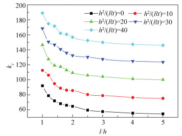
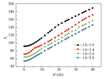
Figs. 4-5 show the effects of the length-height ratio l/h and the parameter h2/(Rt) on the shear buckling coefficient kc.
|
Fig.4 The effects of the length-height ratio l/h on the shear buckling coefficient kc |
|
Fig.5 The effects of the parameter h2/(Rt) on the shear buckling coefficient kc |
As seen from Table 3 and Figs. 4-5, for a given parameter h2/(Rt), the shear buckling coefficient kc decreases with the length-height ratio l/h. For a given length-height ratio l/h, the shear buckling coefficient kc increases with the increase of the parameter h2/(Rt). This implies that the elastic shear buckling strength of a curved bridge web is larger than that of an equivalent straight bridge web. For a curved bridge with the parameter h2/(Rt) less than 2, the amount of increase is less than 4.5%. The elastic shear buckling stress of curved bridge webs can be estimated conservatively as the webs in straight bridges. While for a curved bridge with larger h2/(Rt), using the equations for straight girders to estimate the elastic shear buckling stress is too conservative.
5 Finite Element Analysis and ComparisonsIn this study, the finite element models of curved bridge webs are established using the software program Ansys-15. The results of the theoretical and numerical analysis are then compared.
5.1 Finite Element Model and Material PropertiesIn this study, a pure curved steel web is modeled, and for a conservative consideration, its flanges and stiffeners are replaced with simply supported boundaries, as shown in Table 4. The above models can easily make sure the curved steel web in the state of pure shear.
| Table 4 Boundary conditions of curved steel webs |
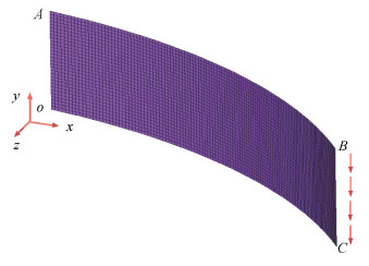
The finite element model for the curved steel webs is shown in Fig. 6. The steel webs adopt the shell63 element. Finite element mesh sizes of 60 mm×60 mm are used for the models. Uniformly distributed shear load is applied on BC edge in y directions to make sure the web under a pure shear state, as shown in Fig. 6. The loading conditions and simple support boundary conditions as mentioned above are verified first by comparing the shear buckling strength of a flat plate calculated from numerical studies with the classical plate buckling theory[23].
|
Fig.6 Finite element model of curved bridge webs |
The elastic modulus E 210 000 MPa and the Poisson's ratio ν is 0.3 throughout the following study.
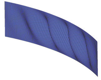
5.2 Numerical Analysis and ComparisonsThe finite element model of curved bridge webs is shown in Fig. 7. The ultimate shear buckling stress of curved webs from finite element analysis and the theoretical results from the formulas (Eqs.(19)-(20)) are shown in Table 5. As can be seen from Table 5, The average value of the ratio between the finite element analysis results and theoretical results τF/τce is 1.015. τF is the shear buckling strength of curved bridge webs from finite element analysis.That is to say the accuracy of the proposed formula is satisfactory.
|
Fig.7 Shear buckling mode of curved bridge webs |
| Table 5 The comparison between finite element analysis results and theoretical results |
6 Conclusions
In this paper, the curved bridge web is equivalent to an isotropic cylindrical flat shell, and the double triangular series satisfying four-edge simply supported boundaries are used as the displacement function of the shell. Then by means of the Galerkin method, the analytical formula for elastic shear buckling stress of curved bridge webs is deduced. Additionally, the table and the equation of the shear buckling coefficient kc are developed. The following conclusions can be drawn:
(1) For a given length-height ratio l/h, the shear buckling coefficient kc increases with the increase of the parameter h2/(Rt).
(2) For a given parameter h2/(Rt), the shear buckling coefficient kc decreases with the increase of the length-height ratio l/h.
(3) The elastic shear buckling stress of a curved bridge web is larger than that of an equivalent straight bridge web. For a curved bridge with the parameter h2/(Rt) less than 2, the amount of increase is less than 4.5%. The elastic shear buckling stress of curved bridge webs can be estimated conservatively as the webs in straight bridges. While for a curved bridge with larger h2/(Rt), using the equations for straight girders to calculate the elastic shear buckling stress is too conservative.
| [1] |
Leggett D M A. The elastic stability of a long and slightly bent rectangular plate under uniform shear. Proceedings of the Royal Society A, 1937, 162(908): 62-83. DOI:10.1098/rspa.1937.0167 (  0) 0) |
| [2] |
Batdorf S B. A simplified method for elastic stability analysis for thin cylindrical shells Ⅱ : modified equilibrium equation. Technical Report Archive & Image Library, 1947, 1-34. (  0) 0) |
| [3] |
Batdorf S B, Stein M, Schildcrout M. Critical shear stress of curved rectangular panels. Technical Report Archive & Image Library, 1947, 110(1348): 139-140. (  0) 0) |
| [4] |
Stein M, Fralich R W. Critical shear stress of infinitely long, simply supported plate with transverse stiffeners. Technical Report Archive & Image Library, 1949, 1851. (  0) 0) |
| [5] |
Stein M, Yaeger D J. Critical shear stress of a curved rectangular panel with a central stiffener. Technical Report Archive & Image Library, 1949. (  0) 0) |
| [6] |
Mariani N, Mozer J D, Dym C L, et al. Transverse stiffener requirements for curved webs. Journal of the Structural Division, 1973, 99(4): 757-771. (  0) 0) |
| [7] |
Elgaaly M, Hamilton R W, Seshadri A. Shear strength of beams with corrugated webs. Journal of Structural Engineering, 1996, 122(4): 390-398. DOI:10.1061/(ASCE)0733-9445(1996)122:4(390) (  0) 0) |
| [8] |
Lee S C, Yoo C H. Strength of curved I-girder web panels under pure shear. Journal of Structural Engineering, 1999, 125(8): 847-853. DOI:10.1061/(ASCE)0733-9445(1999)125:8(847) (  0) 0) |
| [9] |
Lee S C, Davidson J S, Yoo C H. Shear buckling coefficients of plate girder web panels. Computers & Structures, 1996, 59(5): 789-795. DOI:10.1016/0045-7949(95)00325-8 (  0) 0) |
| [10] |
Lee S C, Yoo C H. Strength of plate girder web panels under pure shear. Journal of Structural Engineering, 1998, 124(2): 184-194. DOI:10.1061/(ASCE)0733-9445(1998)124:2(184) (  0) 0) |
| [11] |
Davidson J S, Ballance S R, Yoo C H. Behavior of curved I-girder webs subjected to combined bending and shear. Journal of Bridge Engineering, 2000, 5(2): 165-170. DOI:10.1061/(ASCE)1084-0702(2000)5:2(165) (  0) 0) |
| [12] |
Kim D Y, Jung S K, White D W. Transverse stiffener requirements in straight and horizontally curved steel I-girders. Journal of Bridge Engineering, 2007, 12(2): 174-183. DOI:10.1061/(ASCE)1084-0702(2007)12:2(174) (  0) 0) |
| [13] |
Lee D S, Lee S C. A study on elastic shear buckling coefficients of horizontally curved plate girder web panels. Journal of The Korean Society of Civil Engineers, 2008, 28(3A): 367-373. (  0) 0) |
| [14] |
Nakai H, Kitada T, Ohminami R. Experimental study on buckling and ultimate strength of curved girders subjected to combined loads of bending and shear. Proceedings of the Japan Society of Civil Engineers, 2010(356): 445-454. DOI:10.2208/jscej.1985.356_445 (  0) 0) |
| [15] |
Machaly E B, Safar S S, Abdel-Aal E A. Shear strength of horizontally curved plate girder web panels with transverse stiffeners. Journal of Engineering & Applied Science, 2010, 57(4): 257-276. (  0) 0) |
| [16] |
Keerthan P, Mahendran M. Shear behaviour and strength of LiteSteel beams with web openings. Advances in Structural Engineering, 2012, 15(2): 171-184. DOI:10.1260/1369-4332.15.2.171 (  0) 0) |
| [17] |
Van Bogaert P. Buckling strength of curved bridge girder web panels, including residual stress. IABSE Symposium Report, 2014, 215-222. DOI:10.2749/222137814814027666 (  0) 0) |
| [18] |
Abu-Hamd M, Ei Dib F F. Buckling strength of tapered bridge girders under combined shear and bending. HBRC Journal, 2016, 12(2): 163-174. DOI:10.1016/j.hbrcj.2014.11.001 (  0) 0) |
| [19] |
Van Staen G, Van Bogaert P, De Backer H. Experimental verification of buckling of curved web close steel section. 13th International conference on steel, space and composite structures. Perth, 2018, 45. (  0) 0) |
| [20] |
Martins J P, Ljubinkovic F, da Silva L S, et al. Behaviour of thin-walled curved steel plates under generalised in-plane stresses: A review. Journal of Constructional Steel Research, 2018, 140: 191-207. DOI:10.1016/j.jcsr.2017.10.018 (  0) 0) |
| [21] |
Wu C. Modern Steel Bridge. Beijing: China Communications Press, 2006.
(  0) 0) |
| [22] |
Luo Z D, Li S J. Anisotropic Material Mechanics. Shanghai: Shanghai Jiaotong University Press, 1994.
(  0) 0) |
| [23] |
Timoshenko S P, Gere J M. Theory of elastic stability. Tokyo: McGraw Hill-Kogakusha Ltd., 1961.
(  0) 0) |
| [24] |
CCCC Highway Consultants CO., Ltd. Specifications for Design of Highway Steel Bridge: JTG D64-2015. Beijing: China Communications Press, 2015.
(  0) 0) |
 2019, Vol. 26


