Forward canards are widely used on guided missiles for better dynamic performance because the deflecting direction of the canard surface is the same as the direction of the angle of attack, which makes the ratio of lift and drag greater and the control response faster. Such structural design can change the relative position of the canard surface and the tail surface, and effectively adjust the pressure center of the missile. The control canard surface is close to the inertial guidance component and the missile-loaded computer, which reduces the complexity of the control mechanism[1-2]. However, numerous studies have proved that missiles with forward canards suffer adverse rolling torque[3-5], which can be prevented by using free-spinning tails[6].
The idea of using free-spinning tails has been proposed for many years. In the 1950s, NASA studied a number of free-flighting rolling control devices which were used in aircrafts. In these studies, a free-spinning tail designed in the missile body can improve stability in lengthwise direction and reduce undesired induced rolling moments from the canard deflection[7-8].
During the 1970s, Regan et al.[9] studied the use of free-spinning tails on bombs and missiles as a method to eliminate undesired forces and moments. Blair[10-12] studied the aerodynamic performance of canard control missiles which were controlled by canards with fixed tails and free-spinning tails by experiments, and obtained the variation law of free-spinning tail and fixed tail rolling moments. The results showed that the canard control missile with free-spinning tails can reduce adverse rolling moments. Auman and Kreeger[13] studied the aerodynamic characteristics of canard control missiles with free-spinning tails when the Mach number is from 0.4 to 3.8. Their experiment proved that the free-spinning tail can reduce adverse rolling moments and has almost no influence on the stability and longitudinal aerodynamics of the canard control missile. Based on experimental results, Lesieutre et al.[14] applied engineering- and intermediate-level aerodynamic prediction codes to predict aerodynamic characteristics of canard control missiles with free-spinning tails, and the obtained results were in agreement with the experimental data.
In addition to experimental studies, researchers also carried out many numerical simulation studies. Murman and Aftosmis[15] performed time-dependent and relative-motion simulations on a canard control missile with a free-spinning tail by using an inviscid Cartesian-grid method. The spinning tail forced roll rate of the tail was obtained by two different simulating methods, in which the net rolling moment of the tail components is zero, and the results were compared with free-spinning tail structure which has a passive 6-DOF motion. Their experiment indicated that the application of forced-spin prediction is not accurate enough.
Nygaard[16] studied the application of the Chimera overset grid method to a missile with free-spinning tails. In his study, the aerodynamic force which is a function of deflection angle is insensitive to the tail roll rate, whereas the results accuracy is greatly dependent on the value of the roll rate. The calculated results agreed well with the wind tunnel tests, while the direction of the total force vector is still not resolved.
Liu et al.[17] used the unsteady RANS method and the DDES method to simulate the flow over the high-speed spinning projectile SOCBT. The results showed that the DDES method has great potential for improving the simulation accuracy of Magnus effect of spinning missiles.
On the basis of Navier-Stokes equations, Xu et al.[18] used time dependent method and sliding mesh to predict the rolling characteristics over a spinning missile, and the result showed that rolling moment coefficient varies linearly with rotate rate. Their paper also proposed and verified the empirical equations of rolling moment coefficient and balancing rotating speed under small oblique wing angle and slow rotate rate.
Based on the above research, in addition to the experimental methods, most numerical studies on free-spinning tails or spinning missiles used unsteady methods to simulate the flow field. However, obtaining the aerodynamic parameters of a missile with complex geometric shapes requires a large number of unsteady simulation calculations, which is time- and effort-consuming. In this paper, by simulating the steady flow field of canard missiles on different angles of attack and different Mach numbers with CFD techniques, we proposed a method to greatly reduce the quantity of calculation for the rolling characteristics of canard missiles with free-spinning tails according to the calculation results, and discussed the relations between rolling moment coefficient, Mach number, and angle of attack. Computed data were validated with experimental data and agreed with the wind tunnel test data well, which proved that the method is accurate to calculate rolling characteristics of canard missiles with free-spinning tails and can reduce the quantity of calculation.
2 Missile Geometry and Computational MeshFig. 1 shows the canard missile geometry in this paper which has four forward canards and six tail fins. The ratio of length to diameter of the missile is about 17.

|
Fig.1 Forward canard missile geometry |
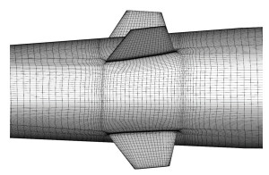
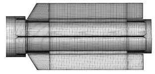
The unstructured hexahedron meshes were generated using the preprocessor, ICEM, and the outer boundary of all the meshes is cylinder-shaped as shown in Fig. 2. The axial distance of the outer boundary is approximately four times of the missile length and the radial distance of the outer boundary is approximately fifteen times of the missile diameter. Meshes of the parts are shown in Figs. 3-5.

|
Fig.2 Outer boundary meshes of computation field |

|
Fig.3 Meshes of the longitudinal section near the missile |
|
Fig.4 Meshes of the canard surfaces |
|
Fig.5 Meshes of the tail surfaces |
3 Numerical Methods
Fluent software was used to simulate the flow field of the canard missile with steady-state by implicit, compressible, density-based, and unstructured-mesh solvers[19]. In this study, the mass conservation equation, momentum conservation, and energy conservation were solved. Considering that the flow in this study was turbulent, a transport equation also needed to be solved. All the conservation equations can be written as the following equations:
| $ \frac{{\partial \rho }}{{\partial t}} + \nabla \cdot (\rho \mathit{\boldsymbol{V}}) = 0 $ | (1) |
| $ \frac{{\partial (\rho \mathit{\boldsymbol{V}})}}{{\partial t}} + \nabla \cdot (\rho \mathit{\boldsymbol{VV}}) = \rho \mathit{\boldsymbol{f}} - \nabla p + \nabla \cdot \mathit{\boldsymbol{\tau }} $ | (2) |
| $ \begin{array}{l} \frac{{\partial (\rho E)}}{{\partial t}} + \nabla \cdot (\rho \mathit{\boldsymbol{VE}}) = \rho \mathit{\boldsymbol{f}} \cdot \mathit{\boldsymbol{V}} - \nabla (p\mathit{\boldsymbol{V}}) + \\ \;\;\;\;\;\;\;\;\;\;\;\;\nabla \cdot (\mathit{\boldsymbol{\tau }} \cdot \mathit{\boldsymbol{V}}) + \cdot (k\nabla T) + S \end{array} $ | (3) |
where ρ is the air density, V is the missile velocity, f is the gravitational body force and external body forces, p is the static pressure, τ is the stress tensor, E is the intrinsic energy of per unit mass, k is the heat conductivity, and S is the energy source term.
For the compressible viscid flow, the ideal gas equation is expressed as follows:
| $ p = \rho RT $ | (4) |
In this study, the Spalart-Allmaras turbulent model was adopted, which is a single equation model where the length scale associated with the thickness of the local shear layer does not need to be calculated. Based on the original equation of the Spalart-Allmaras model, the transport equation for kinematic eddy (turbulent) viscosity is expressed as[20]
| $ \begin{array}{*{20}{l}} {\frac{{\partial v}}{{\partial t}} + \mathit{\boldsymbol{V}} \cdot \nabla \mathit{\boldsymbol{v}} = {c_{b1}}\left( {{f_{r1}} - {f_2}} \right)\mathit{\boldsymbol{Sv}} - }\\ {\;\;\;\;\;\;\;\;\;\frac{1}{{{\rm{Re}}}}\left[ {{c_w}{f_w} - \frac{{{c_{b1}}}}{{{k^2}}}{f_{t2}}} \right]{{\left[ {\frac{\mathit{\boldsymbol{v}}}{d}} \right]}^2} + \frac{1}{{\sigma {\rm{Re}}}}\{ \nabla \cdot }\\ {\;\;\;\;\;\;\;\;\;\left[ {\left( {\mathit{\boldsymbol{v}} + \left( {1 + {c_{b2}}} \right)\mathit{\boldsymbol{v}}} \right)\nabla \mathit{\boldsymbol{v}}} \right] - {c_{b2}}\mathit{\boldsymbol{v}}\nabla \cdot }\\ {\;\;\;\;\;\;\;\;\;(\nabla \mathit{\boldsymbol{v}})\} } \end{array} $ | (5) |
Details of the terms in Eq.(5) can be found in Ref. [20].
The no-slip wall boundary condition was used on the surfaces of the missile body, canard, and tail. Table 1 shows the detailed pressure far field boundary conditions.
| Table 1 Pressure far field boundary conditions |
The rolling moment is the aerodynamic torque around the longitudinal axis of the missile, which is caused by the asymmetrical flow of missiles through the missile, and can be calculated as follows:
| $ {\mathit{\boldsymbol{M}}_x} = \mathit{\boldsymbol{r}} \times \mathit{\boldsymbol{F}} $ | (6) |
where Mx is the rolling moment, r is the distance vector from the rotation axis to the point of action of the force, F is the vector force.
The rolling moment coefficient Cmx is the dimensionless coefficient of rolling moment and is expressed as
| $ {C_{mx}} = \frac{{{M_x}}}{{qAL}} $ | (7) |
where q is the dynamic pressure, A is the reference area, and L is the reference length.
The rolling moment coefficient of the missile with a fixed tail can be calculated by Eq.(7) where the Mx is the rolling moment of the entire missile around the longitudinal axis. For the missile with a free-spinning tail, when the roll control is performed, due to the existence of the free-spinning tail, there is hardly any moment that causes the missile to rotate in the opposite direction to the control direction. Therefore, based on the rolling moment of the missile with a fixed tail, the calculation of that with a free-spinning tail can be obtained:
| $ {C_{mx}} = \frac{{{M_x} - \left( {{M_{x, {\rm{ tail }}}} - {M_{x, f\underline {} {\rm{tail }}}}} \right)}}{{qAL}} $ | (8) |
where Mx, tail is the rolling moment of the fixed tail around the longitudinal axis, and Mx, f_tail is the minimum moment that allows the tail to rotate freely and is ignored. Thus the calculation equation for the rolling moment coefficient of the missile with a free-spinning tail is
| $ {C_{mx}} = \frac{{{M_x} - {M_{x, {\rm{ tail }}}}}}{{qAL}} $ | (9) |
The results of the numerical simulations and the wind tunnel tests are presented in this section. The rolling moment coefficients of the canard missile with a free-spinning tail are discussed in detail.
4.1 Mesh Independence StudyTo ensure the independence of the mesh and save calculation time, a series of mesh sensitivity comparisons were performed. Three different sizes of meshes, i.e., coarse (7 000 000 cells), medium (9 600 000 cells), and fine (12 000 000 cells) meshes were used, respectively.
The calculation results of the three different meshes are presented in Table 2, in which the results (axial force coefficient, normal force coefficient, rolling moment coefficient, and pressure center coefficient) of the coarse meshes had a larger error compared with others. Therefore, the medium-sized meshes are used in this paper.
| Table 2 Calculation results of three different meshes |
4.2 Steady Flow Field Results of the Missile with a Fixed Tail
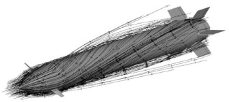
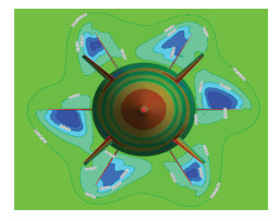
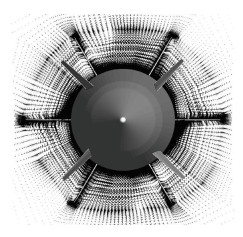
To obtain the steady flow field of the missile with a fixed tail, simulations were carried out with the following parameters: Mach number Ma=1.0, angle of attack α=0°, and the deflection angle of canards is 10°. Results of the steady flow field showed that the canard deflection had a strong effect on the rolling moment of the missile. The streamline distribution around the missile, static pressure contour, and vector field on the normal surface of the tail are shown in Figs. 6-8. Due to the canard deflection, asymmetric flow field developed around the missile. After the air flowed over the canard surfaces, an asymmetrical air flowed on the tail surfaces and produced adverse induced rolling moments.
|
Fig.6 Streamline distribution around the missile |
|
Fig.7 Static pressure contour on the normal surface of the tail |
|
Fig.8 Vector field on the normal surface of the tail |
4.3 Rolling Moment Coefficients Analyses of the Missile with a Free-Spinning Tail
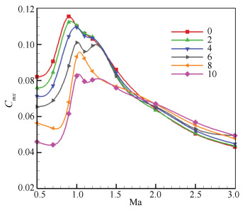
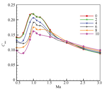
The analyses were performed at ten Mach numbers: 0.5-3.0, two canard deflections: 5° and 10°, and six angles of attack: 0°, 2°, 4°, 6°, 8°, and 10°. The viscous and pressure forces from the computed flow fields of the missile with a fixed tail were integrated along the missile body, canard, and tail surfaces to calculate the rolling moment coefficients. The rolling moment coefficients of the missile with a free-spinning tail were calculated by Eq.(9), and the computed results are shown in Figs. 9-10. For the subsonic cases, the rolling moment coefficient increased with the increase of the Mach number. For the transonic cases, with the change of the angle of attack, the Mach number was different when the maximum rolling moment coefficient occurred. When the angle of attack was 0°-2°, the rolling moment coefficient was the largest when the Mach number was 0.9. When the angle of attack was between 4°-10°, the rolling moment coefficient was the largest when the Mach number was 1.0. For the supersonic cases, the rolling moment coefficient decreased with the increase of the Mach number. Also, with the same canard deflection angle, the rolling moment coefficient changed with the angle of attack. For the subsonic cases, the larger the angle of attack was, the larger the rolling moment coefficient was, while for the supersonic cases, the larger the angle of attack was, the smaller the rolling moment coefficient was.
|
Fig.9 Rolling moment coefficients of 5° canard deflection |
|
Fig.10 Rolling moment coefficients of 10° canard deflection |
4.4 Comparison of the Calculation Results and the Experimental Results
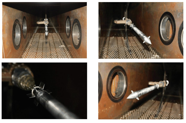
Wind tunnel tests were conducted at the FD-06 wind tunnel in China Academy of Aerospace Aerodynamics (CAAA). The range of the test Mach number at this wind tunnel is 0.4-4.5. In this study, the Mach number range is 0.5-3.0, and the Reynolds number range is 1.189×10⁷-2.851×10⁷. The missile with a free-spinning tail model tested at the wind tunnel is shown in Fig. 11.
|
Fig.11 Missile with a free-spinning tail model tested at the wind tunnel |
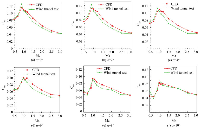
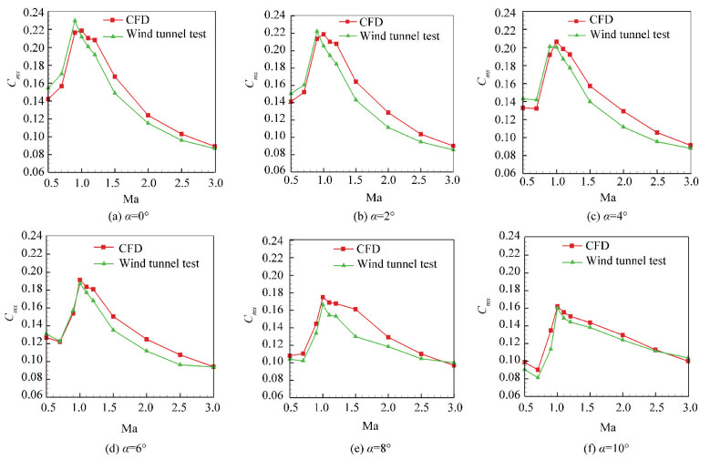
Comparisons of the rolling moment coefficients between wind tunnel tests and numerical calculations are shown in Figs. 12-13. When the range of Mach number is 0.5-3.0 and the angle of attack is 0-10°, all the computed rolling moment coefficients in this study showed very good agreement with the experimental values. Except for a few data points, the errors were within 10%, which proved that the method is accurate enough to calculate the rolling characteristics of a canard missile with a free-spinning tail and can reduce the quantity of calculation.
|
Fig.12 Comparisons of the rolling moment coefficients between wind tunnel tests and numerical calculations at 5° canard deflection |
|
Fig.13 Comparisons of the rolling moment coefficients between wind tunnel tests and numerical calculations at 10° canard deflection |
5 Conclusions
In this paper, a series of CFD simulations were performed to compute the rolling moment coefficients and flow field around a canard-controlled missile with a fixed tail. The results showed that when canards were deflected, the missile with a fixed tail would suffer adverse induced rolling moments, which can be effectively reduced by using a free-spinning tail on the canard-controlled missile. Eq.(9) was applied to calculate the rolling moment coefficient of the missile with a free-spinning tail based on the CFD simulations of the canard missile with a fixed tail. All the computed rolling moment coefficients in this study were greatly in agreement with the experimental results, which proved that the method is accurate to calculate the rolling characteristics of a canard missile with a free-spinning tail and can reduce the quantity of calculation.
| [1] |
Tahani M, Masdari M, Kazemi M. Aerodynamic performance improvement of a canard control missile. Aircraft Engineering and Aerospace Technology, 2017, 89(6): 871-878. DOI:10.1108/AEAT-01-2016-0019 (  0) 0) |
| [2] |
McDaniel M A, Evans C, Lesieutre D J. The effect of tail fin parameters on the induced roll of a canard-controlled missile. Proceedings of 28th AIAA Applied Aerodynamics Conference. Reston: AIAA, 2010. AIAA 2010-4226. DOI: 10.2514/6.2010-4226.
(  0) 0) |
| [3] |
Allen J M, Blair A B. Comparison of analytical and experimental supersonic aerodynamic characteristics of a forward control missile. Journal of Spacecraft and Rockets, 1982, 19(2): 155-159. DOI:10.2514/3.62226 (  0) 0) |
| [4] |
Blair A B, Dillon J L, Watson C B. Experimental study of tail-span effects on a canard-controlled missile. Journal of Spacecraft and Rockets, 1993, 30(5): 635-640. DOI:10.2514/3.25576 (  0) 0) |
| [5] |
DeSpirito J, Vaughn M E Jr., Washington W D. Numerical Investigation of Aerodynamics of Canard-Controlled Missile Using Planar and Grid Tail Fins. Part 1. Supersonic Flow.http://www.arl.army.mil/arlreports/2002/ARL-TR-2848.pdf, 2019-01-09.
(  0) 0) |
| [6] |
Feyzioglu E. Roll Characteristics and Shape Optimization of the Free-to-Rotate Tail-Fins on a Canard-Controlled Missile. Ankara: Middle East Technical University, 2014: 1-4.
(  0) 0) |
| [7] |
Schult E D. Free-Flight Measurements of the Rolling Effectiveness and Operating Characteristics of a Bellows-Actuated Split-Flap Aileron on a 60 Degree Delta Wing at Mach Numbers Between 0.8 and 1.8. https://digital.library.unt.edu/ark:/67531/metadc60629/, 2019-01-09.
(  0) 0) |
| [8] |
English R D. Rocket-Powered-Model Investigation of the Effects of Aeroelasticity on the Rolling Effectiveness of an 8.06-Percent-Scale McDonnell F3H-1 Airplane Wing at Mach Numbers from 0.5 to 1.4. https://digital.library.unt.edu/ark:/67531/metadc53017/, 2019-01-09.
(  0) 0) |
| [9] |
Regan F J, Falusi M E, Holmes J E. The Static and Magnus Aerodynamic Characteristics of the M823 Research Store Equipped with Fixed and Freely Spinning Stabilizers. http://www.dtic.mil/dtic/tr/fulltext/u2/757658.pdf, 2019-01-09.
(  0) 0) |
| [10] |
Blair A B. Wind-Tunnel Investigation at Supersonic Speeds of a Controlled Canard Missile with Fixed and Free-Rolling Tail Fins. https://ntrs.nasa.gov/archive/nasa/casi.ntrs.nasa.gov/19780024124.pdf, 2019-01-09.
(  0) 0) |
| [11] |
Blair A B. Remote-controlled canard missile with a Free-Rolling tail brake torque system. Journal of Spacecraft and Rockets, 1981, 18(6): 550-555. DOI:10.2514/3.57851 (  0) 0) |
| [12] |
Blair A B. Wind-Tunnel Investigation at Supersonic Speeds of a Remote-Controlled Canard Missile with a Free-Rolling Tail Brake Torque System. https://ntrs.nasa.gov/archive/nasa/casi.ntrs.nasa.gov/19870008235.pdf, 2019-01-09.
(  0) 0) |
| [13] |
Auman L M, Kreeger R E. Aerodynamic characteristics of a canard-controlled missile with a free-spinning tail. Proceedings of 36th AIAA Aerospace Sciences Meeting and Exhibit. Reston: AIAA, 1998. AIAA 1998-0410. DOI: 10.2514/6.1998-410.
(  0) 0) |
| [14] |
Lesieutre D, Love J, Dillenius M. Prediction of the nonlinear aerodynamic characteristics of tandem-control and rolling-tail missiles. Proceedings of AIAA Atmospheric Flight Mechanics Conference and Exhibit. Reston: AIAA, 2002: AIAA 2002-4511. DOI: 10.2514/6.2002-4511.
(  0) 0) |
| [15] |
Murman S M, Aftosmis M J. Cartesian-grid simulations of a canard-controlled missile with a spinning tail. Proceedings of 41st AIAA Applied Aerodynamics Conference. Reston: AIAA, 2002. AIAA-2003-3670.DOI: 10.2514/6.2003-3670.
(  0) 0) |
| [16] |
Nygaard T A. Aeromechanic analysis of a missile with freely spinning tailfins. Proceedings of 21st AIAA Applied Aerodynamics Conference. Reston: AIAA, 2003. AIAA 2003-3. DOI: 10.2514/6.2003-3672.
(  0) 0) |
| [17] |
Liu Z, Xie L J, Yang Y J, et al. Unsteady numerical simulation of aerodynamics effect of a spinning projectile. Acta Aeronautica et Astronautica Sinica, 2016, 37(5): 1401-1410. (in Chinese) DOI:10.7527/S1000-6893.2015.0306.(inChinese) (  0) 0) |
| [18] |
Xu K, Wang X, Zhang C, et al. Research on rolling characteristics missile during low spinning speeds. Journal of Ordnance Equipment Engineering, 2018, 39(9): 39-46. (in Chinese) DOI:10.11809/bqzbgcxb2018.09.009.(inChinese) (  0) 0) |
| [19] |
ANSYS, Inc. Ansys Fluent User's Guide. http://www.ansys.com, 2019-01-09.
(  0) 0) |
| [20] |
Spalart P R, Allmaras S R. A one-equation turbulence model for aerodynamic flows. Proceedings of 30th Aerospace Sciences Meeting and Exhibit. Reston: AIAA, 1992. AlAA-92-G439. DOI: 10.2514/6.1992-439.
(  0) 0) |
 2019, Vol. 26


