2. National Demonstration Center for Experimental Mechanical and Electrical Engineering Education, Tianjin University of Technology, Tianjin 300384, China
In mid-twentieth century, Roberson[1] implemented a vibration absorber with nonlinear stiffness in order to widen its working frequency band and improve its robustness. Until the last two decades, scholars have focused mostly on pure nonlinear absorbers, such as the so-called nonlinear energy sink (NES). NES is an efficient, robust, lightweight absorber that can passively absorb energy over wide frequency ranges[2-3]. Various researches of NES have been carried out, which focused mainly on three areas. The first area aims to study the mechanism and complex phenomenon of target energy transfer (TET). The second area focuses on increasing the efficiency of NES by improving its design. The third aspect is concentrated on the specific application of NES in different main structures and under different excitations.
Lin and Oguamanam[4] pointed out that the efficiency of TET is closely related to the 1:1 resonance capture, efficiency enhancement is achieved by using strong nonlinearity attachments. Costa et al.[5] investigated the energy transfer between different oscillators. Starosvetsky and Gendelman[6] investigated the mechanism of TET and demonstrated that quasi-periodic beating responses can exhibit more excellent vibration suppression than a steady-state response.
Al-Shudeifat[7] considered a realization of cubic nonlinear stiffness and investigated energy dissipation of NES under shock excitation. Panagopoulos et al.[8] attained efficient TET through choosing appropriate initial conditions. Fang et al.[9] explored a device which comprises an NES and a giant magnetostrictive material to enhance vibration suppression efficiency and realize energy harvesting. Starosvetsky and Gendelman[10] studied the interaction of a linear oscillator attached with an NES with two degrees of freedom. Starosvetsky and Gendelman[11] investigated the efficiency of NES with nonlinear damping under harmonic excitation and found that the utilization of piecewise-quadratic damping can eliminate higher branches. Ahmadabadi et al.[12] presented an optimal design for a system comprising an NES and a piezoelectric-based vibration energy harvester. Main structure with parallel NES devices attached was investigated for absorbing more input energy and improving the efficiency of TET, and the parallel NES devices were found to perform better than single NES[13-14]. Nguyen and Pernot[15] formulated a design criterion to guide optimization of NES parameters. Moreover, in order to overcome the shortcoming of the traditional NES that they can only mitigate excitation in a relatively narrow range of initial energy, a pendulum NES and an asymmetric magnet-based NES were introduced[16-17].
Viguie and Kerschen[18] investigated the dynamics of a nonlinear system coupled with a nonlinear vibration absorber and devised a qualitative tuning methodology for the absorber. Avramov and Gendelman[19] studied the interaction of a beam with a pure nonlinear vibration absorber. Kani et al.[20] studied the vibration absorption efficiency of a beam attached to an NES under external shock excitation, and it was found that, with the increase of the shock amplitude, the optimum value of stiffness of the NES decreases. Research from Guo[21] found that the application of NES on the reduction of whirling vibration amplitude in rotor systems can significantly reduce the resonant amplitude. Zhang et al.[22] used NES to suppress the vibration of composite laminated plate and found that the amplitude of the plate can be rapidly reduced by the NES. The efficiency of NES can also be attained while the absorber is coupled to a multiple-degree-of-system[23]. Lee et al.[24] used NES to suppress the aeroelastic instability in an experiment. Zhang et al.[25] focused on thermal shock-induced vibration suppression of an axially moving beam with an NES. In Ref.[26], NES was placed on a rotating beam to mitigate vibration, and the best range for the parameters of the NES was found as the one in which strong and weak modulated response occur simultaneously. Besides, in Ref.[27], nonlinear approach was proposed for whole-spacecraft vibration reduction. They found that an appropriately designed NES can efficiently absorb and dissipate broadband-frequency energy.
The above researches demonstrated that NES is effective for many kinds of structures. However, excitation energy below a threshold will hinder TET and NES's activation. Conversely, for too high excitation energy, the dissipation in NES will be greatly reduced. Although NES can absorb energy over wide frequency ranges, the TET in a system can be completed efficiently only within a certain excitation range. The influences of nonlinear stiffness on the energy dissipation of NES have been studied in several papers. However, the relationship between nonlinear stiffness and higher branches of response of a system including NES under large excitation has not been paid much attention to, and the effects of impulse excitation amplitude on the optimum nonlinear stiffness of NES need to be further analyzed. This paper puts forward a variable-stiffness NES scheme, aiming to overcome the reduction of NES performance with the increase of external load.
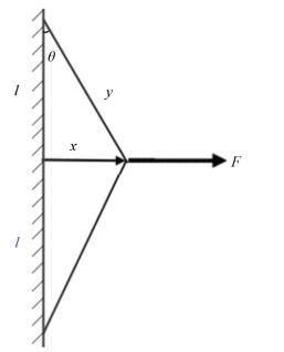
2 Realization of Variable StiffnessIn Fig. 1, the cubic stiffness is realized by an elastic string with sufficient length and both ends clamped.
|
Fig.1 Realization of variable-stiffness |
l denotes the half length of the effective string that clamps between the ends, which can be varied by changing the position of the two ends, and k denotes the axial equivalent stiffness of the string. Force F is applied at the middle of the string between the ends. Under the action of F, each half of the string is stretched to length y. The change in length is denoted by Δy, the offset distance from its initial position is marked as x, and the drift angle as θ. The relationship between the force and the change of length can be written as:
| $ F = 2k\Delta y\sin \theta $ | (1) |
Using geometric relations, we obtain:
| $ \Delta y = y - l = \sqrt {{l^2} + {x^2}} - l,\sin \theta = x/\sqrt {{l^2} + {x^2}} $ | (2) |
Substituting Eq. (2) into Eq. (1):
| $ F = 2kx\left( {1 - l/\left( {\sqrt {{l^2} + {x^2}} } \right)} \right) $ | (3) |
Eq. (4) is the Taylor expansion of the term >1/
| $ \frac{1}{{\sqrt {{l^2} + {x^2}} }} = \frac{1}{l} - \frac{{{x^2}}}{{2{l^3}}} + \frac{{3{x^4}}}{{8{l^5}}} + o\left( {{x^4}} \right) $ | (4) |
By neglecting higher order terms, restoring force caused by cubic stiffness can be expressed as:
| $ F \approx \left( {k/{l^2}} \right){x^3} $ | (5) |
This result shows that the cubic stiffness can be adjusted by varying the parameter l, i.e., the effective half length of the string between the two ends.
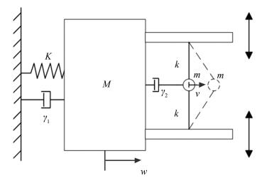
3 Response Under Harmonic ExcitationThe coupled system comprised of a linear oscillator (LO) and an NES with its nonlinear stiffness adjustable is depicted in Fig. 2. Two movable parts below the LO allow the length of the string to become adjustable but do not change the axial equivalent stiffness of the string. The double sided arrows in this figure denote the direction of motion of the movable parts. The equations of motion of the system driven by harmonic excitation are deduced as:
|
Fig.2 Target energy transfer system |
| $ \left( \begin{array}{l} \ddot w + {\gamma _1}\dot w + {\omega ^2}w + \frac{k}{{{l^2}}}{(w - v)^3} + {\gamma _2}(\dot w - \dot v) = \\ \;\;\;\;\;A\cos \mathit{\Omega }t\\ \varepsilon \ddot v + \frac{k}{{{l^2}}}{(v - w)^3} + {\gamma _2}(v - \dot w) = 0 \end{array} \right. $ | (6) |
where w and v denote the displacements of the LO and the NES, ω denotes the linear natural frequency of the LO, γ1 and γ2 denote the damping coefficients of the LO and the NES, respectively. A denotes the amplitude of the harmonic excitation, Ω denotes the frequency of the harmonic excitation, ε denotes the mass ratio between the NES and the LO, and 0 < ε≪1. For simplicity, M=1 is chosen for all cases.
Letting u=w-v, Eq. (6) can be expressed as:
| $ \left\{ {\begin{array}{*{20}{l}} {\ddot w + {\gamma _1}\dot w + {\omega ^2}w + \frac{k}{{{l^2}}}{u^3} + {\gamma _2}\dot u = A\cos \mathit{\Omega }t}\\ {\varepsilon (\ddot w - \ddot u) - \frac{k}{{{l^2}}}{u^3} - {\gamma _2}\dot u = 0} \end{array}} \right. $ | (7) |
We introduce the following transformations:
| $ \dot w + {\rm{i}}\mathit{\Omega }w = {\alpha _1}{{\rm{e}}^{{\rm{i}}\mathit{\Omega }t}},\dot u + {\rm{i}}\mathit{\Omega }u = {\alpha _2}{{\rm{e}}^{{\rm{i}}\mathit{\Omega }t}} $ | (8) |
where α1 and α2 are functions of t, and i is the imaginary unit. Subsequently, we obtain:
| $ \begin{array}{l} w = \frac{{{\alpha _1}{{\rm{e}}^{{\rm{i}}\mathit{\Omega t}}} - {{\bar \alpha }_1}{{\rm{e}}^{ - {\rm{i}}\mathit{\Omega t}}}}}{{2{\rm{i}}\mathit{\Omega }}},\dot w = \frac{{{\alpha _1}{{\rm{e}}^{i\Omega t}} + {{\bar \alpha }_1}{{\rm{e}}^{ - {\rm{i}}\Omega t}}}}{2}\\ \ddot w = 0.5\left( {{{\dot \alpha }_1}{{\rm{e}}^{{\rm{i}}\mathit{\Omega }t}} + {\rm{i}}\mathit{\Omega }{\alpha _1}{{\rm{e}}^{{\rm{i}}\mathit{\Omega }t}} + {{\dot {\bar \alpha} }_1}{{\rm{e}}^{ - {\rm{i}}\mathit{\Omega }t}} - {\rm{i}}\mathit{\Omega }{{\bar \alpha }_1}{{\rm{e}}^{ - {\rm{i}}\mathit{\Omega t}}}} \right)\\ u = \frac{{{\alpha _2}{{\rm{e}}^{{\rm{i}}\mathit{\Omega }t}} - {{\bar \alpha }_2}{{\rm{e}}^{ - {\rm{i}}\mathit{\Omega }t}}}}{{2{\rm{i}}\mathit{\Omega }}},\dot u = \frac{{{\alpha _2}{{\rm{e}}^{{\rm{i}}\mathit{\Omega }t}} + {{\bar \alpha }_2}{{\rm{e}}^{ - {\rm{i}}\mathit{\Omega t}}}}}{2}\\ \ddot u = 0.5\left( {{{\dot \alpha }_2}{{\rm{e}}^{{\rm{i}}\mathit{\Omega }t}} + {\rm{i}}\mathit{\Omega }{\alpha _2}{{\rm{e}}^{{\rm{i}}\mathit{\Omega }t}} + {{\dot {\bar \alpha} }_2}{{\rm{e}}^{ - {\rm{i}}\mathit{\Omega }t}} - {\rm{i}}\mathit{\Omega }{{\bar \alpha }_2}{{\rm{e}}^{ - {\rm{i}}\mathit{\Omega }t}}} \right) \end{array} $ | (9) |
where α1, α2 are the complex conjugates of α1 and α2, respectively. The slow flow equations can be derived by substituting Eq. (9) into Eq. (7):
| $ \left\{ \begin{array}{l} {{\dot \alpha }_1} + {\rm{i}}\mathit{\Omega }{\alpha _1} + {\gamma _1}{\alpha _1} + \frac{{{\omega ^2}{\alpha _1}}}{{{\rm{i}}\mathit{\Omega }}} + \frac{{3k\alpha _2^2{{\bar \alpha }_2}}}{{4{l^2}{\rm{i}}{\mathit{\Omega }^3}}} + {\gamma _2}{\alpha _2} = A\\ \varepsilon \left( {{{\dot \alpha }_1} + {\rm{i}}\mathit{\Omega }{\alpha _1} - {{\dot \alpha }_2} - {\rm{i}}\mathit{\Omega }{\alpha _2}} \right) - \frac{{3k\alpha _2^2{{\bar \alpha }_2}}}{{4{l^2}{\rm{i}}{\mathit{\Omega }^3}}} - {\gamma _2}{\alpha _2} = 0 \end{array} \right. $ | (10) |
Ansatz α1=a1+ib1 and α2=a2+ib2 are used, where a1, b1, a2, b2 are functions of t. Substituting these into Eq. (10) and separating the real and imaginary part yields:
| $ \left\{ \begin{array}{l} {{\dot a}_1} = - {a_1}{\gamma _1} + {b_1}\mathit{\Omega } - \frac{{{\omega ^2}{b_1}}}{\mathit{\Omega }} - \frac{{3k{b_2}\left( {a_2^2 + b_2^2} \right)}}{{4{l^2}{\mathit{\Omega }^3}}} - {\gamma _2}{a_2} + A\\ {{\dot b}_1} = - {a_1}\mathit{\Omega } - {b_1}{\gamma _1} + \frac{{{\omega ^2}{a_1}}}{\mathit{\Omega }} + \frac{{3k{a_2}\left( {a_2^2 + b_2^2} \right)}}{{4{l^2}{\mathit{\Omega }^3}}} - {\gamma _2}{b_2}\\ {{\dot a}_2} = - {a_1}{\gamma _1} + {b_2}\mathit{\Omega } - \frac{{{\omega ^2}{b_1}}}{\mathit{\Omega }} - \left( {1 + \frac{1}{\varepsilon }} \right)\left( {\frac{{3k{b_2}\left( {a_2^2 + b_2^2} \right)}}{{4{l^2}{\mathit{\Omega }^3}}} + } \right.\\ \;\;\;\;\;\;\;\;\left. {{\gamma _2}{a_2}} \right) + A\\ {{\dot b}_2} = - {b_1}{\gamma _1} - {a_2}\mathit{\Omega } + \frac{{{\omega ^2}{a_1}}}{\mathit{\Omega }} + \left( {1 + \frac{1}{\varepsilon }} \right)\left( {\frac{{3k{a_2}\left( {a_2^2 + b_2^2} \right)}}{{4{l^2}{\mathit{\Omega }^3}}} - } \right.\\ \;\;\;\;\;\;\;\left. {{\gamma _2}{b_2}} \right) \end{array} \right. $ | (11) |
Letting ȧ1=0,
| $ \left\{ \begin{array}{l} {a_1}{\gamma _1} - {b_1}\mathit{\Omega } + \frac{{{\omega ^2}{b_1}}}{\mathit{\Omega }} + \frac{{3k{b_2}\left( {a_2^2 + b_2^2} \right)}}{{4{l^2}{\mathit{\Omega }^3}}} + {\gamma _2}{a_2} = A\\ {a_1}\mathit{\Omega } + {b_1}{\gamma _1} - \frac{{{\omega ^2}{a_1}}}{\mathit{\Omega }} - \frac{{3k{a_2}\left( {a_2^2 + b_2^2} \right)}}{{4{l^2}{\mathit{\Omega }^3}}} + {\gamma _2}{b_2} = 0\\ {a_1}{\gamma _1} - {b_2}\mathit{\Omega } + \frac{{{\omega ^2}{b_1}}}{\mathit{\Omega }} + \left( {1 + \frac{1}{\varepsilon }} \right)\left( {\frac{{3k{b_2}\left( {a_2^2 + b_2^2} \right)}}{{4{l^2}{\mathit{\Omega }^3}}} + } \right.\\ \;\;\;\;\;\;\left. {{\gamma _2}{a_2}} \right) = A\\ {b_1}{\gamma _1} + {a_2}\mathit{\Omega } - \frac{{{\omega ^2}{a_1}}}{\mathit{\Omega }} - \left( {1 + \frac{1}{\varepsilon }} \right)\left( {\frac{{3k{a_2}\left( {a_2^2 + b_2^2} \right)}}{{4{l^2}{\mathit{\Omega }^3}}} - } \right.\\ \;\;\;\;\;\;\left. {{\gamma _2}{b_2}} \right) = 0 \end{array} \right. $ | (12) |
The amplitude of the LO is denoted by Aw and it can be calculated using the following expression:
| $ {A_w} = \left( {\sqrt {a_1^2 + b_1^2} } \right)/\mathit{\Omega } $ | (13) |
To determine whether the steady state response of the system is stable or not, let
| $ {a_1} = {a_{10}} + {\delta _1} $ | (14a) |
| $ {b_1} = {b_{10}} + {\delta _2} $ | (14b) |
| $ {a_2} = {a_{20}} + {\delta _3} $ | (14c) |
| $ {b_2} = {b_{20}} + {\delta _4} $ | (14d) |
where, a10, b10, a20, b20 are the stable solutions of Eq. (11) and δn (n=1, 2, 3, 4) denotes a small disturbance of each stable solution. Taking into account the change of variables (14) and preserving the linear part of the disturbance, Eq. (11) can be rewritten as:
| $ \left\{ \begin{array}{l} {{\dot \delta }_1} = - {\gamma _1}{\delta _1} + \mathit{\Omega }{\delta _2} - \frac{{{\omega ^2}}}{\mathit{\Omega }}{\delta _2} - \frac{{3k}}{{4{l^2}{\mathit{\Omega }^3}}} \cdot \\ \;\;\;\left[ {\left( {a_{20}^2 + 3b_{20}^2} \right){\delta _4} + 2{a_{20}}{b_{20}}{\delta _3}} \right] - {\gamma _2}{\delta _3}\\ {{\dot \delta }_2} = - {\gamma _1}{\delta _2} - \mathit{\Omega }{\delta _1} + \frac{{{\omega ^2}}}{\mathit{\Omega }}{\delta _1} + \frac{{3k}}{{4{l^2}{\mathit{\Omega }^3}}} \cdot \\ \;\;\;\left[ {\left( {3a_{20}^2 + b_{20}^2} \right){\delta _3} + 2{a_{20}}{b_{20}}{\delta _4}} \right] - {\gamma _2}{\delta _4}\\ {{\dot \delta }_3} = - {\gamma _1}{\delta _1} + \mathit{\Omega }{\delta _4} - \frac{{{\omega ^2}}}{\mathit{\Omega }}{\delta _2} - \left( {1 + \frac{1}{\varepsilon }} \right) \cdot \\ \;\;\;\left\{ {\frac{{3k}}{{4{l^2}{\mathit{\Omega }^3}}}\left[ {\left( {a_{20}^2 + 3b_{20}^2} \right){\delta _4} + 2{a_{20}}{b_{20}}{\delta _3}} \right] + {\gamma _2}{\delta _3}} \right\}\\ {{\dot \delta }_4} = - {\gamma _1}{\delta _2} - \mathit{\Omega }{\delta _3} + \frac{{{\omega ^2}}}{\mathit{\Omega }}{\delta _2} + \left( {1 + \frac{1}{\varepsilon }} \right) \cdot \\ \;\;\;\left\{ {\frac{{3k}}{{4{l^2}{\mathit{\Omega }^3}}}\left[ {\left( {3a_{20}^2 + b_{20}^2} \right){\delta _3} + 2{a_{20}}{b_{20}}{\delta _4}} \right] - {\gamma _2}{\delta _4}} \right\} \end{array} \right. $ | (15) |
The characteristic roots of the coefficient matrix of Eq. (15) can determine the stability of the solution, i.e., the solution can be regarded as stable if all the characteristic roots' real parts are negative.
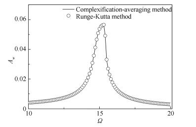
In this section, the parameters are set to ε=0.1, γ1=0.1, γ2=0.2, k=1 500, ω=15, while the frequency of harmonic excitation Ω changes from 10 to 20, the results can be obtained by solving Eq. (12) with Maple solve function. At first, we set l=1, corresponding to NES stiffness of knl=1 500. To prove the accuracy of the approximation obtained above, numerical results were obtained from Eq. (6) with Runge-Kutta method. When the amplitude of the harmonic force A=0.4, frequency response of the coupled system can be obtained, as shown in Fig. 3. Results obtained by the complexification-averaging method are pretty close with that obtained by Runge-Kutta method. Fig. 4 shows the frequency response of the LO with and without NES attached, under a harmonic excitation with an amplitude A=0.4. It can be seen that LO has a stable solution throughout the excitation band and the NES adequately absorbs the vibration energy at this amplitude of excitation.
|
Fig.3 Frequency response of the LO with NES attached for A=0.4 |

|
Fig.4 Frequency response of the LO with and without NES attached |
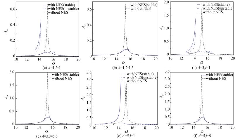
In Fig. 5, we made a further increase of the excitation amplitude, multiple solutions were found by solving Eq. (12) in some specific frequency band. When the excitation amplitude A=1, as shown in Fig. 5(a), unstable solutions appear in band Ω=14.8-16.2, which are usually presented as strongly modulated response, and this is beneficial to vibration reduction [28]. However, two new branches appear in the frequency band Ω=13.0-14.0, i.e., a stable higher branch and an unstable higher branch. In this band, the frequency response of LO may follow the two stable branches according to the accumulation of vibration energy, the vibration of LO stabilizes at the higher branch when enough energy accumulates, which causes its amplitude greatly increases.
|
Fig.5 Frequency responses of the coupled system |
When A=3, as shown in Fig. 5(c), the bands of strongly modulated response and the higher branches widen and the amplitude of LO increases. Furthermore, the efficiency of NES under this excitation becomes insufficient. An increase of the amplitude to A=5, as shown in Fig. 5(e), causes the merging of the higher branch and the lower branch, and a single stable solution appears in frequency band Ω=10-16.3. In addition, the amplitude of LO greatly increases and NES has a negligible effect on the LO, only changing the resonance frequency of the coupled system. The appearance of the higher branches and its merging with the lower branch causes NES to lose its efficacy. To eliminate the higher branches so as to enhance the efficiency of the NES, we varied the parameter l=1.5, l=6.5 and l=9 to suit the amplitude of excitation A=1, A=3 and A=5, and then recalculated the response of the system. As is depicted in Fig. 5(b), Fig. 5(d), and Fig. 5(f), the variable stiffness NES eliminates the higher branches and significantly limits the amplitude of LO, showing good vibration reduction efficiency.
The frequency band of strongly modulated response of the system under different excitation amplitudes is shown in Fig. 6. As the parameter l increases, i.e., the nonlinear stiffness knl decreases, there seems to be no strongly modulated response at first, which is caused by the merging of higher and lower branches. As l increases, the higher branch and the lower branch separate, frequency band of strongly modulated response begins to appear and gradually widens. When l continues to increase, with the elimination of the higher branches, the strongly modulated response band begins to narrow, and finally disappears around the natural frequency of the LO. According to the fact that the band of strongly modulated response is beneficial to the vibration absorption of NES and its widening can also be the sign of the emergence of the higher branch, it is best to maintain that this band exists only near the natural frequency of the LO by adjusting the nonlinear stiffness of the NES for better vibration absorption efficiency.

|
Fig.6 Frequency band of unstable solution of the coupled system |
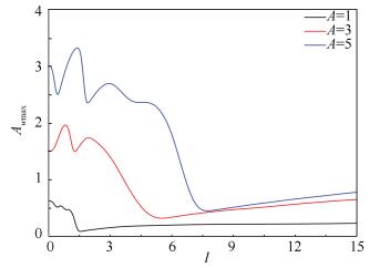
Fig. 7 depicts the maximum amplitude of the LO under different excitation amplitudes and for varying NES stiffness parameter. As the parameter l increases, after a transient fluctuation, the maximum of amplitude of the primary oscillator rapidly decreases to a minimum. Subsequently, the amplitude remains at a relatively low level due to the elimination of the higher branch. However, setting the parameter l too large would also affect the performance of the NES. It also can be concluded that if the amplitude of excitation changes in a wide range and only constant-stiffness NES can be used, the nonlinear stiffness should be set to a low value in order to enhance efficiency.
|
Fig.7 Maximum of amplitude of the LO |
4 Simulation Under Impulse Excitation
Impulse excitation can be simulated by appropriately setting the initial velocity of the LO. We set l=1.8, l=3.5, l=8 and set the initial velocity of LO to ẇ0=3, ẇ0=5, ẇ0=10, and compared with the system with l=1. In this section, the results were obtained from solving Eq. (6) with Runge-Kutta method.
As shown in Fig. 8, the black line denotes the transient response of the LO with parameter l=1, and the blue line denotes the response when the studied parameter is l=1.8, l=3.5, and l=8. For l=1, the amplitude of the LO decreases relatively slowly for every initial velocity. Conversely, the NES with parameters l=1.8, l=3.5 and l=8 all cause rapid attenuation of the response of the LO. In particular, in Fig. 8(b), for ẇ0=5, after 4 seconds the blue line which denotes the amplitude of the LO is already less than 0.02, whereas the same value of the black line is reached only after 11 seconds. The results indicate that compared with constant stiffness NES, variable-stiffness NES possesses superior vibration suppression efficiency, if the stiffness is well adjusted with the excitation amplitudes.

|
Fig.8 Comparison of the transient response of the coupled system |
With the purpose of making further investigation of the vibration suppression efficiency of the variable-stiffness NES, we introduced Ediss(t), which denotes the ratio of energy dissipated to the input energy.
| $ {E_{{\rm{diss}}}}(t) = 100\frac{{{\gamma _2}\int_0^t {(\dot w(} \tau ) - \dot v(\tau ){)^2}{\rm{d}}\tau }}{{\frac{1}{2}M\dot w{{(0)}^2}}} $ | (16) |
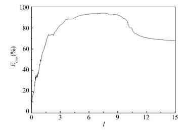
Fig. 9 shows this quantity of the variable stiffness NES as a percentage of the impulse magnitude for A=10 and t=14 s.
|
Fig.9 Energy dissipated of the variable-stiffness NES with A=10 |
As the parameter l increases, the rate of dissipated energy increases rapidly. The absorber performs well for l=4-9, with the ratio reaching up to 90%. If the parameter l is further increased to above 10, the nonlinear stiffness of the absorber becomes small and the efficiency begins to decrease.
However, a satisfactory ratio of energy dissipation (about 70 percent) can still be attained, supporting our harmonic excitation research. In other words, an optimum NES stiffness interval exists for each excitation amplitude, as in the case of vibration absorption efficiency. Prior to this interval (where the stiffness is too high), the performance of NES is unsatisfactory and unstable, and beyond this interval, any decrease of nonlinear stiffness will decrease the efficiency of the NES.
A contour plot is shown in Fig. 10 to investigate the relation of the vibration energy dissipated in the variable stiffness NES, the impulse magnitude ẇ(0), and the nonlinear stiffness parameter l. Colors in these figures denote different levels of energy dissipation. In the system, a linear oscillator coupled with a variable-stiffness NES and energy is dissipated sufficiently over a large range of impulse magnitudes, which means the variable-stiffness NES can absorb and dissipate vibration energy efficiently within a larger range of initial input energies. Beyond that, with the increase of impulse magnitude, higher energy dissipation efficiency can be obtained by increasing the parameter l accordingly.

|
Fig.10 Energy dissipated of the variable-stiffness NES vs. impulse magnitude (ẇ(0)) and the parameter of nonlinear stiffness (l) |
5 Conclusions
The vibration absorption efficiency of a variable-stiffness NES was investigated in this work. Realization of the variable stiffness was presented. The approximated dynamic equation of the studied system was obtained by complexification-averaging method, after which the stability of the solutions was analyzed. The results show that while the system was under harmonic excitation, increasing excitation amplitude made the system produce the higher and lower branches of the frequency response. These branches merged when the excitation amplitude was further increased, making the NES loses its efficacy. The higher branches can be eliminated and the efficiency of NES enhanced by tuning the parameter of nonlinear stiffness in accordance with the excitation amplitude. Furthermore, while the system was under impulse excitation, the variable-stiffness NES possessed the ability to suppress the amplitude of the primary oscillator and improve energy dissipation efficiency. The results indicate the optimum stiffness of NES is inversely proportional to the amplitude of excitation.
In many fields, especially aeronautics and astronautics, the external excitation amplitude varies widely, and characteristics such as light weight and broadband vibration absorption make NES indispensable. However, the efficiency of constant stiffness NES is influenced by changes in the excitation amplitude. The design of semi-active variable-stiffness systems can make NES well suited for a wide range of applications, and with only a few devices attached. This paper aims to explore a way to enhance the efficiency of the NES under variable loads. The details of the control method of the device were not discussed here. Consequently, the design of semi-active variable-stiffness NES for different primary structures is an open question and of great practical engineering significance.
| [1] |
Roberson R E. Synthesis of a nonlinear dynamic vibration absorber. Journal of the Franklin Institute, 1952, 254(3): 205-220. DOI:10.1016/0016-0032(52)90457-2 (  0) 0) |
| [2] |
Vakakis A F. Inducing passive nonlinear energy sinks in vibrating systems. Journal of Vibration and Acoustics-Transactions of the ASME, 2001, 123(3): 324-332. DOI:10.1115/1.1368883 (  0) 0) |
| [3] |
Gendelman O V. Transition of energy to a nonlinear localized mode in a highly asymmetric system of two oscillators. Nonlinear Dynamics, 2001, 25(1-3): 237-253. DOI:10.1007/978-94-017-2452-4_13 (  0) 0) |
| [4] |
Lin D C, Oguamanam D C D. Targeted energy transfer efficiency in a low-dimensional mechanical system with an essentially nonlinear attachment. Nonlinear Dynamics, 2015, 82(1-2): 971-986. DOI:10.1007/s11071-015-2211-1 (  0) 0) |
| [5] |
Costa S N J, Hassmann C H G, Balthazar J M, et al. On energy transfer between vibrating systems under linear and nonlinear interactions. Nonlinear Dynamics, 2009, 57(1-2): 57-67. DOI:10.1007/s11071-008-9419-2 (  0) 0) |
| [6] |
Starosvetsky Y, Gendelman O V. Attractors of harmonically forced linear oscillator with attached nonlinear energy sink. Ⅱ: Optimization of a nonlinear vibration absorber. Nonlinear Dynamics, 2008, 51(1-2): 47-57. DOI:10.1007/s11071-006-9168-z (  0) 0) |
| [7] |
Al-Shudeifat M A. Highly efficient nonlinear energy sink. Nonlinear Dynamics, 2014, 76(4): 1905-1920. DOI:10.1007/s11071-014-1256-x (  0) 0) |
| [8] |
Panagopoulos P N, Gendelman O, Vakakis A F. Robustness of nonlinear targeted energy transfer in coupled oscillators to changes of initial conditions. Nonlinear Dynamics, 2007, 47(4): 377-387. DOI:10.1007/s11071-006-9037-9 (  0) 0) |
| [9] |
Fang Z W, Zhang Y W, Li X, et al. Integration of a nonlinear energy sink and a giant magnetostrictive energy harvester. Journal of Sound and Vibration, 2017, 391: 35-49. DOI:10.1016/j.jsv.2016.12.019 (  0) 0) |
| [10] |
Starosvetsky Y, Gendelman O V. Interaction of nonlinear energy sink with a two degrees of freedom linear system: Internal resonance. Journal of Sound and Vibration, 2010, 329(10): 1836-1852. DOI:10.1016/j.jsv.2009.11.025 (  0) 0) |
| [11] |
Starosvetsky Y, Gendelman O V. Vibration absorption in systems with a nonlinear energy sink: Nonlinear damping. Journal of Sound and Vibration, 2009, 324(3): 916-939. DOI:10.1016/j.jsv.2009.02.052 (  0) 0) |
| [12] |
Ahmadabadi Z N, Khadem S E. Nonlinear vibration control and energy harvesting of a beam using a nonlinear energy sink and a piezoelectric device. Journal of Sound and Vibration, 2014, 333(19): 4444-4457. DOI:10.1016/j.jsv.2014.04.033 (  0) 0) |
| [13] |
Zhang Y W, Zhang Z, Chen L Q, et al. Impulse-induced vibration suppression of an axially moving beam with parallel nonlinear energy sinks. Nonlinear Dynamics, 2015, 82(1-2): 61-71. DOI:10.1007/s11071-015-2138-6 (  0) 0) |
| [14] |
Vaurigaud B, Savadkoohi A T, Lamarque C H, et al. Efficient targeted energy transfer with parallel nonlinear energy sinks: Theory and experiments. J. Comput. Nonlinear Dynam., 2011, 6(4): 041005. DOI:10.1115/1.4003687 (  0) 0) |
| [15] |
Nguyen T A, Pernot S. Design criteria for optimally tuned nonlinear energy sinks-part 1: transient regime. Nonlinear Dynamics, 2012, 69(1-2): 1-19. DOI:10.1007/s11071-011-0242-9 (  0) 0) |
| [16] |
Farid M, Gendelman O V. Tuned pendulum as nonlinear energy sink for broad energy range. Journal of Vibration and Control, 2015, 23(3): 373-388. DOI:10.1177/1077546315578561 (  0) 0) |
| [17] |
Al-Shudeifat M A. Asymmetric magnet-based nonlinear energy sink. Journal of Computational and Nonlinear Dynamics, 2015, 10(1): 014502. DOI:10.1115/1.4027462 (  0) 0) |
| [18] |
Viguie R, Kerschen G. Nonlinear vibration absorber coupled to a nonlinear primary system: A tuning methodology. Journal of Sound and Vibration, 2009, 326(3-5): 780-793. DOI:10.1016/j.jsv.2009.05.023 (  0) 0) |
| [19] |
Avramov K V, Gendelman O V. On interaction of vibrating beam with essentially nonlinear absorber. Meccanica, 2010, 45(3): 355-365. DOI:10.1007/s11012-009-9252-9 (  0) 0) |
| [20] |
Kani M, Khadem S E, Pashaei M H, et al. Design and performance analysis of a nonlinear energy sink attached to a beam with different support conditions. Proceedings of the Institution of Mechanical Engineers Part C-Journal of Mechanical Engineering Science, 2016, 230(4): 527-542. DOI:10.1177/0954406215578705 (  0) 0) |
| [21] |
Guo C, Al-Shudeifat M A, Vakakis A F, et al. Vibration reduction in unbalanced hollow rotor systems with nonlinear energy sinks. Nonlinear Dynamics, 2015, 79(1): 527-538. DOI:10.1007/s11071-014-1684-7 (  0) 0) |
| [22] |
Zhang Y W, Zhang H, Hou S, et al. Vibration suppression of composite laminated plate with nonlinear energy sink. Acta Astronautica, 2016, 123: 109-115. DOI:10.1016/j.actaastro.2016.02.021 (  0) 0) |
| [23] |
Tripathi A, Grover P, Kalmar-Nagy T, et al. On optimal performance of nonlinear energy sinks in multiple-degree-of-freedom systems. Journal of Sound and Vibration, 2017, 388: 272-297. DOI:10.1016/j.jsv.2016.10.025 (  0) 0) |
| [24] |
Lee Y S, Kerschen G, Michael McFarland D, et al. Suppressing aeroelastic instability using broadband passive targeted energy transfers, part 2: Experiments. AIAA Journal, 2007, 45(10): 2391-2400. DOI:10.2514/1.28300 (  0) 0) |
| [25] |
Zhang Y W, Yuan B, Fang B, et al. Reducing thermal shock-induced vibration of an axially moving beam via a nonlinear energy sink. Nonlinear Dynamics, 2017, 87(2): 1159-1167. DOI:10.1007/s11071-016-3107-4 (  0) 0) |
| [26] |
Bab S, Khadem S E, Mahdiabadi M K, et al. Vibration mitigation of a rotating beam under external periodic force using a nonlinear energy sink. Journal of Vibration and Control, 2015, 23(6): 1-25. DOI:10.1177/1077546315587611 (  0) 0) |
| [27] |
Yang K, Zhang Y W, Ding H, et al. Nonlinear energy sink for whole-spacecraft vibration reduction. Journal of Vibration and Acoustics, 2017, 139(2): 021011. DOI:10.1115/1.4035377 (  0) 0) |
| [28] |
Gendelman O V. Targeted energy transfer in systems with external and self-excitation. Part C: Journal of Mechanical Engineering Science, 2011, 225(9): 2007-2043. DOI:10.1177/0954406211413976 (  0) 0) |
 2020, Vol. 27


