2. School of Electrical & Electronic Engineering, Nanyang Technological University, Singapore 639798, Singapore
With the development of large power grid interconnection, disturbance occurring in the interconnected power grid are extended to neighboring areas. If oscillation cannot be inhibited in time, it may cause serious power system fault. For AC/DC interconnected power grid, due to the rapid regulation characteristics and overload capacity of HVDC, exerting additional transient control on it can restrain grid oscillation and improve interconnected power grid stability. A large number of experts and scholars have conducted extensive research in this aspect[1-10].
DC emergency power support is an effective method to damp power oscillation in AC/DC power grid. Refs. [10-11] study the DC active power and reactive power modulation to increase the transient stability of AC/DC system. In terms of designing auxiliary damping controller, there are mainly two kinds of designing methods. One is model-based method, the other is model-free method[12]. For model-based methods, because the system order is high, the mathematical model of the system usually needs to be obtained through the identification method[13]. Recently, extensive research have been carried out, which propose power oscillation damping and maintain the frequency stability of the interconnection system applying sliding mode control[14], model predictive control[15-16], neuro-fuzzy feedback linearization[17], and Lyapunov theory[18]. Limiting factors of emergency DC power support are studied in Ref.[19]. As can be seen from the literature, present research on HVDC emergency power support mainly focuses on two aspects:
1) Research on limiting factors of power support.
Owing to the need to consume a large amount of reactive power during HVDC normal operation, the reactive power limitation needs to be considered when the DC active power is increased. In addition, the power limitation of the DC system itself is taken into account.
2) Research on emergency power support amount.
The emergency power support amount is an extremely important parameter for damping system oscillation. The appropriate amount can effectively suppress grid oscillation. If the amount is not suitable, it will not only fail to damp the system oscillation, but also deteriorate the system.
How to determine the amount of power support is an extremely important research topic. The key factor that determines the amount of power support is the system unbalanced power. According to current research work on emergency power support, we find that the determination of emergency power support needs complex calculation[20-21], which is time-consuming and difficult to achieve on-line dynamic support. With the application of wide area measurement system (WAMS) in power system, HVDC wide area additional control becomes possible. Based on this, the extended state observer (ESO) of unbalanced power is established to realize on-line estimation of system unbalanced power, and then to optimize the emergency power support by considering the constraint conditions. Finally, the principle of ladder-increasing is adopted to realize the goal of emergency power support. Through the simulation of multi-infeed HVDC system, the effectiveness of the method in this paper is verified.
2 Emergency Power Support MechanismIn the study of transient stability of power system, the system is often equivalent to a two-machine instability mode. The system is divided into a critical group S and a remaining group A, so the problem of the power angle stability becomes the relative oscillation of the critical group S to the remaining group A. The transient equations of the critical group S and the remaining group A are as follows:
| $ \left\{\begin{array}{l} \dot{\delta}_{S}=\omega_{S} \\ \dot{\omega}_{S}=\frac{1}{M_{S}} \sum\limits_{i \in S}\left[P_{m i}-P_{e i}\right] \end{array}\right. $ | (1) |
| $ \left\{\begin{array}{l} \dot{\delta}_{A}=\omega_{A} \\ \dot{\omega}_{A}=\frac{1}{M_{A}} \sum\limits_{j \in A}\left[P_{m j}-P_{e j}\right] \end{array}\right. $ | (2) |
where
| $ \begin{array}{l} {\delta _S} = \frac{1}{{{M_S}}}\sum\limits_{i \in S} {{M_i}{\delta _i}, {\omega _S} = \frac{1}{{{M_S}}}\sum\limits_{i \in S} {{M_i}{\omega _i}} } \\ {\delta _A} = \frac{1}{{{M_A}}}\sum\limits_{j \in A} {{M_j}{\delta _j}} , {\omega _A} = \frac{1}{{{M_A}}}\sum\limits_{j \in A} {{M_j}{\omega _j}} \\ {M_S} = \sum\limits_{i \in S} {{M_i}} , {M_A} = \sum\limits_{j \in A} {{M_j}} \end{array} $ |
where MS, δS, ωS, Pmi, and Pei are the equivalent inertial time constant, power angle, angular frequency, mechanical power of unit i, and electromagnetic power of the critical group S, respectivel y; MA, δA, ωA, Pmj, and Pej are the variables of the remaining group A corresponding to the above, respectively.
Combining Eq. (1) with Eq. (2), the transient state equation of the two-machine system can be equivalent to the single-machine system, and the rotor motion equation of the equivalent single-machine system is
| $ \left\{ \begin{array}{l} {{\dot \delta }_{SA}} = {\omega _{SA}}\\ {{\dot \omega }_{SA}} = \frac{1}{{{M_S}}}\sum\limits_{i \in S} {\left[ {{P_{mi}} - {P_{ei}}} \right]} - \frac{1}{{{M_A}}}\sum\limits_{j \in A} {[{P_{mj}} - {P_{ej}}]} \end{array} \right. $ | (3) |
where δSA=δS-δA, ωSA=ωS-ωA. For the above equivalent single-machine system, when the system is in steady-state operation,
In the case of generator fault or large power load sudden start in the critical group S, the situation will result in an instantaneous shortfall in the power of the critical group S. When the mechanical power in the critical group S is less than the electromagnetic power, the rotor will slow down. If power support is equivalent to mechanical power, by adding the emergency power support measures, formula (3) becomes
| $ \left\{ \begin{array}{l} {{\dot \delta }_{SA}} = {\omega _{SA}}\\ {{\dot \omega }_{SA}} = \frac{1}{{{M_S}}}\sum\limits_{i \in S} {\left[ {\left( {{P_{mi}} + \mathit{\Delta} {P_m}} \right) - {P_{ei}}} \right] - } \\ \;\;\;\;\;\;\;\;\;\frac{1}{{{M_A}}}\sum\limits_{j \in A} {[\left( {{P_{mj}} - \mathit{\Delta} {P_m}} \right) - {P_{ej}}]} \end{array} \right. $ | (4) |
where ΔPm is the amount of DC emergency power support. From Eq.(4), it can be seen that through the additional DC emergency power support measures, the rotor frequency difference can be reduced, thus achieving the goal of stabilizing the power angle. The appropriate ΔPm plays an active role in stabilizing the power angle, and inappropriate ΔPm may worsen the system performance. Obviously, ΔPm plays a vital role in regulating the system unbalanced power. The unbalanced power changes dynamically due to the system's own regulation and load response. Through on-line estimation of unbalanced power of the system, dynamic emergency power support is achieved.
3 Unbalanced Power EstimatorThe diagnosis of power system faults or disturbances using ESO have been studied in Ref. [22]. A virtual fault is constructed by introducing additional parameters into the HVDC state equation, and the fault is estimated by an iterative solution. Ref.[23] uses ESO method to achieve the motor rotor flux observation. ESO is the central component of active disturbance rejection control (ADRC) [24]. In a broader sense, ESO is a practical disturbance observer[25], which can deal with uncertain problems such as unknown system parameters, unknown load disturbance, etc.
Based on the previous studies, this paper proposes the application of ESO to study unbalanced power estimation in AC/DC interconnected systems. By equalizing the unbalanced power into a disturbance state quantity, its size is estimated, and an emergency power support strategy is formulated.
3.1 Basic Principle of the Extended State EstimatorThe general expression of the system mathematical model is
| $ \left\{ \begin{array}{l} {x^n} = f\left( {x, \dot x, \ldots , {x^{(n - 1)}}, w\left( t \right)} \right) + bu\\ y = x \end{array} \right. $ | (5) |
where w(t) is unknown disturbance of the system, f(x,
Make x1(t)=x(t), x2(t)=
| $ \left\{ \begin{array}{l} {{\dot x}_1}\left( t \right) = {x_2}\left( t \right)\\ {{\dot x}_2}\left( t \right) = {x_3}\left( t \right)\\ \vdots \\ {{\dot x}_n}\left( t \right) = f\left( {x, \dot x, \ldots , {x^{(n - 1)}}, w\left( t \right)} \right) + bu\\ {{\dot x}_{n + 1}}\left( t \right) = \dot a\left( t \right)\\ y = {x_1}(t) \end{array} \right. $ | (6) |
where xn+1(t) is the expansion state of the system, which can be estimated in real time. For the system (6), its expansion state observer is established as follows:
| $ \left\{ \begin{array}{l} e = {z_1} - y\\ {{\dot z}_1} = {z_2} - {\beta _1}e\\ {{\dot z}_2} = {z_3} - {\beta _2}{\rm{fal}}\left( {e, \alpha /2, d} \right)\\ {{\dot z}_3} = {z_4} - {\beta _3}{\rm{fal}}\left( {e, \alpha /4, d} \right)\\ \vdots \\ {{\dot z}_n} = {z_{n + 1}} - {\beta _n}{\rm{fal}}\left( {e, \alpha /{2^{n - 1}}, d} \right) + bu\\ {{\dot z}_{n + 1}} = - {\beta _{n + 1}}{\rm{fal}}(e, \alpha /{2^n}, d) \end{array} \right. $ | (7) |
where z1, …, zn are the state estimated values of the original system, zn+1 is the expansion state of the system, i.e., the estimated value of the unknown function, β1, …, βn+1 are parameters of the extended state observer, and fal(·) is a non-smooth function as follows:
| $ {\mathop{\rm fal}\nolimits} (e \cdot \alpha \cdot d) = \left\{ {\begin{array}{*{20}{l}} {|e{|^\alpha }{\mathop{\rm sign}\nolimits} (e), }&{|e| > d}\\ {e/{d^{1 - \alpha }}, }&{|e| \le d} \end{array}} \right. $ |
where 0 < α≤1 and d is related to sampling step.
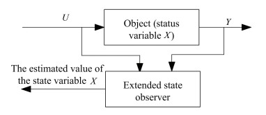
Eq.(7) shows that the system state can be estimated from the input and output of the system as long as the observer parameters are properly chosen, and the extended state observer is shown in Fig. 1.
|
Fig.1 Extended state observer |
3.2 Construction of Unbalanced Power Estimator
The system angular frequency is defined as the equivalent angular velocity of its Center of Inertia (COI) as follows:
| $ {\omega _{{\rm{COI}}}} = \frac{1}{{{M_{JT}}}}\sum\limits_{i = 1}^n {{M_{Ji}}{\omega _i}} \;\;\;\;\;(i = 1, 2, \ldots , n) $ |
where
The relationship between generator frequency change rate and system power variation is as follows[26]:
| $ \dot f = \frac{{{f_0}}}{{{M_{JT}}}}\left( {{P_m} - {P_e}} \right) = \frac{{{f_0}}}{{{M_{JT}}}}\mathit{\Delta} P $ | (8) |
where
In Eq.(8), take (f0/MJT)ΔP as the disturbance of the system, mark it as w(t), then it can be written as follows:
| $\dot f = w(t) $ | (9) |
Eq. (9) represents a 0 input system, which can be written as a state equation as follows:
| $ \left\{ \begin{array}{l} {{\dot x}_1}\left( t \right) = {x_2}\left( t \right)\\ {{\dot x}_2}\left( t \right) = \dot a\left( t \right)\\ y = {x_1}(t) \end{array} \right. $ |
where x1(t)=f, x2(t)=a(t)=(f0/MJT)ΔP.
According to the ESO principle, it can be written as an extended state observer as follows:
| $ \left\{ \begin{array}{l} e = {z_1} - y\\ {{\dot z}_1} = {z_2} - {\beta _1}e\\ {{\dot z}_2} = - {\beta _2}{\rm{fal}}(e, \alpha /2, d) \end{array} \right. $ |
where z1 is the estimated value of f, and z2 is the expansion state of the system, i.e., the estimated value of the (f0/MJT)ΔP. Therefore, by establishing the system's extended state observer, on-line estimation of the unbalanced power can finally be achieved. Mark the unbalanced power as
| $ \mathit{\Delta} {P_{m0}} = - \mathit{\Delta} \hat P = \frac{{ - {z_2} \times {M_{JT}}}}{{{f_0}}} $ |
As for the actual power support, power support is not necessarily equal to the amount of ΔPm0 due to the impact of power support constraints, so ΔPm0 is called pseudo control, but it should have a certain relationship with ΔPm0.
4 Emergency Power Support Strategy OptimizationWithout considering the dynamic characteristics of HVDC transmission lines, HVDC can be represented by a first-order inertia link. The dynamic process of HVDC power can be expressed as follows:
| ${\dot P_{{\rm{dc}}}} = \frac{1}{{{T_d}}}\left( { - {P_{{\rm{dc}}}} + {P_{{\rm{dcREF}}}} + \mathit{\Delta} {P_m}} \right) $ | (10) |
where PdcREF is the set-point of HVDC power, Td is the equivalent time constant of HVDC system, ΔPm is control variable of the system. ΔPm is not necessarily equal to ΔPm0 due to various influences such as self-regulation of grid, load characteristics, and power support constraints. Make ΔPm=k·ΔPm0, 0≤k≤1, substitute it into formula (10), then
| $ {\dot P_{{\rm{dc}}}} = \frac{1}{{{T_d}}}\left( { - {P_{dc}} + {P_{{\rm{dcREF}}}} + k\cdot\mathit{\Delta} {P_{m0}}} \right) $ |
where k is control variable, which is related to the AC system frequency, equivalent inertia time constant. The value of k is limited by many factors, which can be optimized by means of power support constraints.
4.1 Emergency Power Support Limiting FactorsWhether the DC system can reach the power which sets a value in accordance with the power boost command mainly depends on two limiting factors. One is the level of AC bus voltage, which is essentially due to the HVDC need to consume a large amount of reactive power in the promotion of active power, thus making reactive power insufficient and bus voltage drop, consequently resulting in the DC system's inability to effectively enhance the power support. This limiting factor is directly related to the strength of AC system. The other limiting factor is the transmission capacity of the DC system itself. The HVDC system generally has 1.1 times long-term overload capability and 1.5 times short-time overload ability. In addition to overload operation, the DC transmission system also has the minimum power limit, which is determined by the minimum current limiting factor of the DC system. When the current is lower than the limit value, the DC current will be cut off.
For the limitation of AC system bus voltage, the voltage sensitivity factor (VSF) is defined to evaluate the limit of the AC system bus voltage level to the power increase in this paper. Specifically, it is defined as
| $ {F_{{\rm{VSF}}}} = \frac{{\mathit{\Delta} U}}{{{U_N}}} $ | (11) |
where ΔU is the AC bus voltage drop caused by the increase of DC power, UN is the rated value of AC system bus voltage. Substitute k·ΔPm0 into formula (11), then
| $k\cdot\mathit{\Delta} {P_{m0}}\cdot{F_{{\rm{VSF}}}} = \frac{{k\cdot\mathit{\Delta} {P_{m0}}\cdot\mathit{\Delta} U}}{{{U_N}}} $ |
If the value of k·ΔPm0·ΔU is in the range of the voltage fluctuation, the value of k is 1, the power boost is equal to the unbalanced power estimated by the observer. Otherwise, it is in accordance with the maximum admissible voltage fluctuation to calculate the value of k. The limitation factor of HVDC transmission capacity itself can be realized by limiting amplitude.
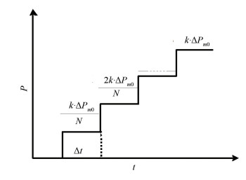
4.2 Ladder-Increasing Principle for Power SupportBased on the kinetic theory and kinematics theory, once the equilibrium state of the object is broken, the external force should be adjusted in real time according to the movement state of the object so as to make the object smoothly transit into a new equilibrium state. Based on this, in case of emergency power support, power angle oscillation curve needs to be monitored in real time and made stable in a small scope in the whole transient transition period so as to ensure the smooth transition from transient state to stable state. Substitute ΔPm=k·ΔPm0 into formula (4):
| $ \begin{array}{l} {{\dot \omega }_{SA}} = \frac{1}{{{M_S}}}\sum\limits_{i \in S} {\left[ {\left( {{P_{mi}} + k\cdot\mathit{\Delta} {P_{m0}}} \right) - {P_{ei}}} \right] - } \\ \;\;\;\;\;\;\;\;\frac{1}{{{M_A}}}\sum\limits_{j \in A} {[\left( {{P_{mj}} - k\cdot\mathit{\Delta} {P_{m0}}} \right) - {P_{ej}}]} \end{array} $ |
where the
|
Fig.2 Power ladder-increasing principle |
In Fig. 2, the value of N is affected by the intensity of the AC system. When the AC system is strong, the value of N can be appropriately reduced. Conversely, the value of N is appropriately increased. According to previous studies, the value of N ranging between 5 and 8 is more appropriate.
4.3 Multi-Infeed Power Support FactorTheoretically, during the fault period, each HVDC of the multi-infeed HVDC transmission system can achieve power balance for the AC/DC interconnected system by increasing the amount of power, but additional control effect on different HVDC has certain different influence. Multi-infeed power support factor is often used to select the optimal HVDC system for power support, which is defined as the product of AC/DC interaction factor (ADIF) or multi-infeed interaction factor (MIIF) and multi-infeed effective short circuit ratio (MESCR). ADIF was utilized to measure the degree of electrical coupling between AC and DC for AC/DC parallel transmission system. The greater the value is, the closer the connection is. MIIF is a measure of the degree of electrical coupling between DC system and DC system for multiple DC parallel transmission system. The greater the value is, the closer the connection is.
ADIF is defined as
| $ {F_{{\rm{ADIF}}, ji}} = \frac{{\mathit{\Delta} {U_j}}}{{\mathit{\Delta} {U_i}}} $ |
where ΔUi is the voltage change of converter bus caused by switching a shunt reactive power branch on it when the DC system running at the rated power; ΔUj is substation bus voltage response variation for the AC system to be observed. FMIIF, ji is multi-infeed interaction factor and has the same definition as FADIF, ji, except that here ΔUj is expressed as the voltage variation in the DC converter station bus to be observed.
MESCR is defined as
| $ {K_{{\rm{MESCR}}i}} = \frac{{{S_{aci}} - {Q_{CNi}}}}{{{P_{dNi}} + \sum\limits_{j, j \ne i} {\left( {{F_{{\rm{MIIF}}, ji}} \times {P_{dNj}}} \right)} }} $ |
where Saci is the three-phase short-circuit capacity of the converter i; QCNi is the reactive power supplied by filter and shunt capacitor of AC bus in converter station; PdNi and PdNj are rated capacity of DC system i and j.
Power support factor is defined as
| $ {\lambda _{j, i}} = {F_{{\rm{ADIF}}, ji}} \times {K_{{\rm{MESCR}}i}} $ |
The optimal control location for the multi-infeed HVDC system can be chosen by the maximum DC power support factor and achieve the best power support effect.
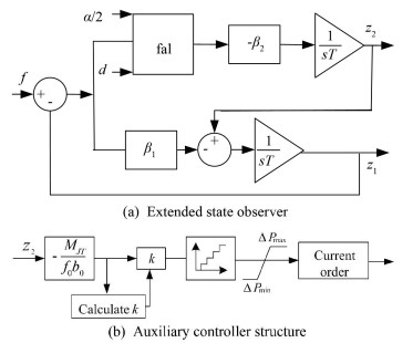
4.4 Optimal Emergency Power Support StrategyIn summary, the optimal emergency power support strategy can be obtained in this paper. First of all, the optimal control location is selected through the power support factor, then the unbalanced power can be estimated based on extended state observer, and power support optimization can be estimated based on power support constraints. Finally, power support can be realized based on the principle of ladder-increasing. The control structure is shown in Fig. 3.
|
Fig.3 Power support control structure |
Fig. 3(a) is an extended state observer control structure, and f is the frequency of the equivalent inertial center of the AC system; Fig. 3(b) is an auxiliary controller structure for the emergency power support.
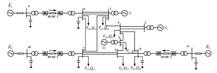
5 Simulation AnalysesThe three-HVDC transmission system with three machines was built on PSCAD, and the topology is shown in Fig. 4. In this system, three HVDC lines all adopt standard CIGRE model, rectifier side fixed DC current control, and inverter side fixed turn-off angle control. The power of all the HVDC lines is Pdc=1 000 MW, Vdc=500 kV. The generator model adopts detailed six-order model, which both contains excitation and speed regulation system, and all of them are not equipped with power system stabilizer. The generator G1 and G3 rated capacity are 700 MVA, G2 is 512 MVA, and inertia time constants of the three generators are H=6.5 s.
|
Fig.4 Three-HVDC transmission system with three machines |
Firstly, the parameters of the second-order extended state observer are adjusted, and the tuning principle and the empirical parameter setting formula are used to adjust the parameters[25]:
| $ \left\{ \begin{array}{l} d = h\\ {\beta _1} = 1/h\\ {\beta _2} = 1/(3h) \end{array} \right. $ |
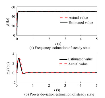
where h is the sampling step size. The effects of each parameter on system performance are as follows: when α and d increase, the tracking of the state becomes slower, the steady state error becomes smaller; when β1 increases, the tracking of the state becomes slower, the steady state error increases, and the overshoot decreases little; when β2 increases, the tracking of the state becomes faster, the steady-state error increases, and the overshoot increases. Finally, the observer parameters are set for α/2=0.5, d=0.05, β1=20, β2=50. When the system is in steady state, the performance of the observer was tested, and the test results are shown in Fig. 5.
|
Fig.5 Steady-state output |
It can be seen from Fig. 5, when the system is in steady-state operation, the rated frequency is 50 Hz. As shown in Fig. 5, the unbalanced power of the system is 0. The estimated value of the observer is equal to the actual value of the system, and the actual value can be tracked quickly, which proves that the performance of the observer is good and the parameter setting is reasonable.
The system model established in this paper is three-infeed HVDC system, so there is no AC tie line. Therefore, only the multi-infeed interaction factors are calculated, and the factors is presented in Table 1.
| Table 1 Interaction factors matrix of DC/DC |
The MESCR of HVDC1 is 3.56, HVDC2 is 3.78, and HVDC3 is 4.67. When the active power imbalance is caused by internal disturbance of the AC system, only MESCR index can be used to select the optimal control location, i.e., HVDC3 is the optimal additional control location for the internal disturbance.
It can be seen from Table 2 that when HVDC2 fails, the control effect of HVDC3 is better than that of HVDC1; when HVDC3 fails, the control effect of HVDC2 is better than that of HVDC1.
| Table 2 DC power support factors |
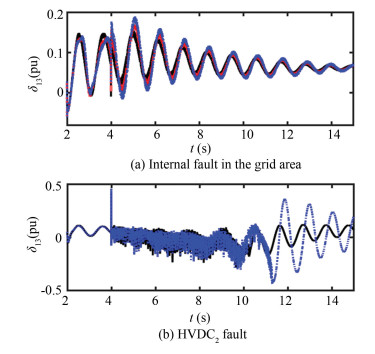
Firstly, the correctness of the control position selection was verified. Set two types of disturbance: type 1 is internal disturbance of AC system, which loses 552WM in BUS3 at 2 s and returns to normal operation at 4 s; type 2's HVDC2 fault occurs at 2 s and is cleared at 4 s, then HVDC2 restarts. Comparison of different HVDC control effects are shown in Fig. 6.
|
Fig.6 Control effects comparison |
It can be seen from Fig. 6(a) that in Case 1, the control effect of HVDC3 is slightly better than HVDC2 and the control effect of HVDC2 is slightly better than HVDC1. For AC system faults, it is proved correct to select the optimal DC according to the MESCR indicator. In Case 2, the control effect of HVDC3 is better than HVDC1. For DC system faults, it is proved correct to use the multi-feed power support factor to select the optimal DC. Through the comparison of simulation results, the correctness of the control position selection method is proved.
The following three cases were used to verify the effectiveness of adaptive emergency power support strategy proposed in this paper.
Case 1: 652MW is lost in BUS2 at 3 s due to fault.
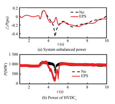
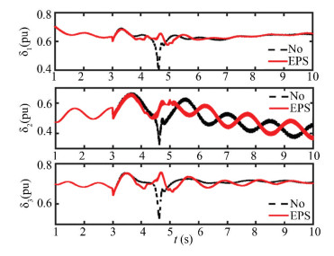
The simulation results are shown in Figs. 7-8.
|
Fig.7 Power curves in Case 1 |
|
Fig.8 Power angle curves in Case 1 |
Fig. 7 (a) is the dynamic unbalanced power of the system estimated by the extended state observer. It can be seen from the diagram that the unbalanced power of the system is a dynamic quantity rather than a constant value. The black-dotted line is the unbalanced power of the system when the emergency power support controller is not put into use, and the solid red curve is the unbalanced power after the emergency power support controller is put into use. Comparison shows that the power balance in the system can be achieved quickly and stably after the emergency power controller is put into use.
Fig. 7 (b) is the HVDC3 power response curve. After the emergency power controller is put into use, the power balance can be realized quickly.
Fig. 8 is power angle curve of G1, G2, and G3. Comparison shows that it can effectively restrain the swing of generator power angle after the emergency power controller is put into use, and make system relatively smoothly transit to a steady state.
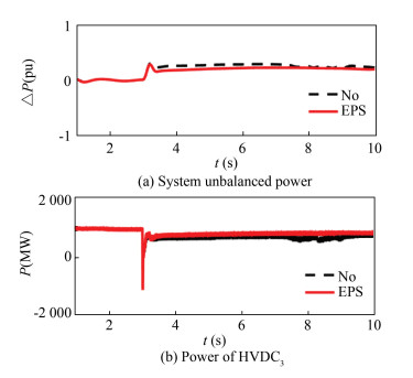
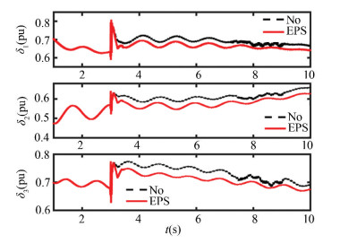
Case 2: 700WM load suddenly increases in BUS6 at 3 s.
The simulation results are shown in Figs. 9-10.
|
Fig.9 Power curves in Case 2 |
|
Fig.10 Power angle curve in Case 2 |
Fig. 9(a) is the dynamic unbalanced power of the system estimated by the extended state observer. Fig. 9(b) is the HVDC3 power response curve. Fig. 10 is the power angle curve of G1, G2 and G3. As can be seen from Fig. 10, with additional power control, the power angle offsets of the three generators are very small and recover quickly. The simulation results shows that the control effect is also very good for Case 2, as shown in Figs. 9-10.
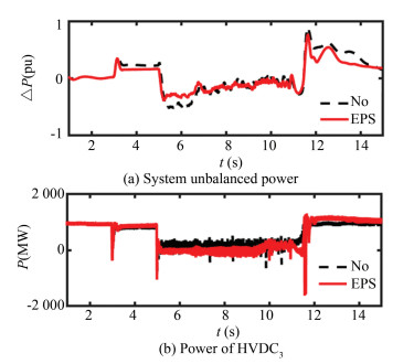
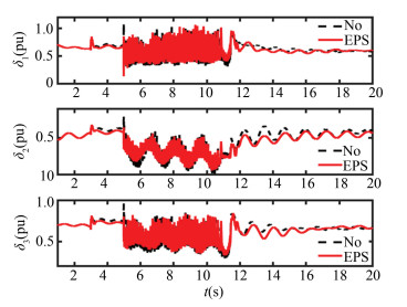
Case 3: HVDC2 is outage at 3 s and the fault is cleared at 5 s, then HVDC2 restarts.
From Figs. 11-12, it can be seen that the proposed method can also exert positive control effect for HVDC fault.
|
Fig.11 Power curves in Case 3 |
|
Fig.12 Power angle curve in Case 3 |
Through the simulation analysis and comparison of the three cases above, it can be found that the proposed method in this paper can dynamically and adaptively adjust the power transmission by itself according to the operating status of the system, and is effective in suppressing the power system oscillation. Therefore, the method is proved to be effective and robust.
6 ConclusionsIn this paper, an adaptive emergency power support method based on the system unbalanced power on-line estimation was proposed, and the effectiveness of the proposed method was verified by simulation analysis. There are two main conclusions:
1) Power system unbalanced power changes dynamically during the transient process. Expanded state estimator can estimate unbalanced power online. Based on the estimated value, dynamic power support can be achieved.
2) For different types of power disturbance, there exists an optimal additional control location. For AC system internal faults, the maximum value of MESCR is used to select the optimal HVDC, and for HVDC faults, the maximum value of the multi-infeed power support factor is used to select the optimal HVDC.Selecting optimal power support realizes optimal power support with minimal control costs.
3) This method does not require complicated calculations and is easy to implement compared to existing methods.
The proposed method in this paper is a self-adaptable emergency power support method, which provides reference for the additional transient control of the actual AC/DC system.
| [1] |
Renedo J, Garcı A, Rouco L. Active power control strategies for transient stability enhancement of AC/DC grids with VSC-HVDC multi-terminal systems. IEEE Transactions on Power Systems, 2016, 31: 4595-4604. DOI:10.1109/TPWRS.2016.2517215 (  0) 0) |
| [2] |
Azad S P, Taylor J A, Iravani R. Decentralized supplementary control of multiple lcc-hvdc links. IEEE Transactions on Power Systems, 2016, 31: 572-580. DOI:10.1109/TPWRS.2015.2393372 (  0) 0) |
| [3] |
Ahmad S, Khan L. Adaptive feedback linearization based HVDC damping control paradigm for power system stability enhancement. Proceedings of the 2016 International Conference on Emerging Technologies (ICET). Piscataway: IEEE, 2016. 1-6. DOI: 10.1109/ICET.2016.7813240.
(  0) 0) |
| [4] |
Darabian M, Jalilvand A, Azari M. Power system stability enhancement in the presence of renewable energy resources and HVDC lines based on predictive control strategy. International Journal of Electrical Power & Energy Systems, 2016, 80: 363-373. DOI:10.1016/j.ijepes.2016.01.050 (  0) 0) |
| [5] |
Pipelzadeh Y, Chaudhuri B, Green T C. Control coordination within a VSC HVDC link for power oscillation damping: A robust decentralized approach using homotopy. IEEE Transactions on Control Systems Technology, 2013, 21: 1270-1279. DOI:10.1109/TCST.2012.2202285 (  0) 0) |
| [6] |
Massmann J, Roehder A, Fuchs B, et al. Stability enhancement by VSC-HVDC with a supplementary frequency control strategy in case of system splits. Proceedings of the 2016 Electric Power Quality and Supply Reliability (PQ). Piscataway: IEEE, 2016. 151-156. DOI: 10.1109/PQ.2016.7724105.
(  0) 0) |
| [7] |
Wang W, Beddard A, Barnes M, et al. Analysis of active power control for VSC-HVDC. IEEE Transactions on Power Delivery, 2014, 29: 1978-1988. DOI:10.1109/TPWRD.2014.2322498 (  0) 0) |
| [8] |
Zeng G, Li X Y, Liu T Q, et al. Multi-channel wide area adaptive damping control for suppressing low frequency and sub-synchronous oscillation. Acta Physica Sinica, 2014, 63: 228801-1-228801-9. DOI:10.7498/aps.63.228801 (  0) 0) |
| [9] |
Li C S, Liu T Q, Liu L B, et al. An auto disturbance rejection controller of multi-HVDC. Transactions of China Electrotechnical Society, 2015, 30: 10-17. DOI:10.19595/j.cnki.1000-6753.tces.2015.07.002 (  0) 0) |
| [10] |
Vovos N A, Galanos G D. Enhancement of the transient stability of integrated AC/DC systems using active and reactive power modulation. IEEE Transactions on Power Apparatus and Systems, 1985, 104: 1696-1702. DOI:10.1109/TPAS.1985.319201 (  0) 0) |
| [11] |
Harnefors L, Johansson N, Zhang L, et al. Interarea oscillation damping using active power modulation of multi terminal HVDC transmissions. IEEE Transactions on Power Systems, 2014, 29(5): 2529-2538. DOI:10.1109/TPWRS.2014.2306826 (  0) 0) |
| [12] |
Shen Y, Yao W, Wen J Y, et al. Adaptive supplementary damping control of VSC-HVDC for interarea oscillation using GrHDP. IEEE Transactions on Power Systems, 2018, 33(2): 1777-1789. DOI:10.1109/TPWRS.2017.2720262 (  0) 0) |
| [13] |
Eriksson R, Söder L. Optimal coordinated control of multiple HVDC links for power oscillation damping based on model identification. European Transactions on Electrical Power, 2012, 22: 188-205. DOI:10.1002/etep.554 (  0) 0) |
| [14] |
Weng H, Xu Z. WAMS based robust HVDC control considering model imprecision for AC/DC power systems using sliding mode control. Electric Power Systems Research, 2013, 95: 38-46. DOI:10.1016/j.epsr.2012.08.008 (  0) 0) |
| [15] |
Azad S P, Iravani R, Tate J.E. Damping inter-area oscillations based on a model predictive control (MPC) HVDC supplementary controller. IEEE Transactions on Power Systems, 2013, 28: 3174-3183. DOI:10.1109/TPWRS.2013.2247640 (  0) 0) |
| [16] |
Fuchs A, Imhof M, Demiray T, et al. Stabilization of large power systems using VSC-HVDC and model predictive control. IEEE Transactions on Power Delivery, 2014, 29: 480-488. DOI:10.1109/TPWRD.2013.2280467 (  0) 0) |
| [17] |
Ahmad S, Khan L. Performance analysis of conjugate gradient algorithms applied to the neuro-fuzzy feedback linearization-based adaptive control paradigm for multiple HVDC links in AC/DC power system. Energies, 2017, 10: 819-841. DOI:10.3390/en10060819 (  0) 0) |
| [18] |
Eriksson R. Coordinated control of multi terminal DC grid power injections for improved rotor angle stability based on Lyapunov theory. IEEE Transactions on Power Delivery, 2014, 29: 1789-1797. DOI:10.1109/TPWRD.2013.2293198 (  0) 0) |
| [19] |
Weng H, Xu Z, Xu F, et al. Research on constraint factor of emergency power support of HVDC systems. Proceedings of the CSEE, 2014, 34: 1519-1527. DOI:10.13334/j.0258-8013.pcsee.2014.10.002 (  0) 0) |
| [20] |
Zhu L, Wang X R, Lu C C, et al. Research of emergency DC power support strategies for large-scale power grid based on PSD-BPA. Power System Protection and Control, 2013, 41: 139-144. (  0) 0) |
| [21] |
Wang Y, Liu B, Liu T B, et al. Coordinated optimal dispatching of emergency power support among provinces after UHVDC transmission system block fault. Proceedings of the CSEE, 2015, 35: 2695-2702. DOI:10.13334/j.0258-8013.pcsee.2015.11.007 (  0) 0) |
| [22] |
Yan B Y, Tian Z H, Shi S J, et al. A new method for fault diagnosis in HVDC systems. Automation of Electric Power Systems, 2007, 31: 57-61. (  0) 0) |
| [23] |
Lin F, Zhang C P, Song W C, et al. Flux observer of induction motor based on extended state observer. Proceedings of the CSEE, 2003, 23: 145-147. DOI:10.13334/j.0258-8013.pcsee.2003.04.029 (  0) 0) |
| [24] |
Han J Q. The extended state observer of a class of uncertain system. Control and Decision, 1995, 10: 85-88. DOI:10.13195/j.cd.1995.01.85.hanjq.020 (  0) 0) |
| [25] |
Han J Q. Active Disturbance Rejection Control. Beijing: National Defense Industry Press, 2013: 184-192.
(  0) 0) |
| [26] |
Krishayya P C S, Adapa R, Holm M, et al.IEEE guide for planning DC links terminating at AC locations having low short-circuit capacities.Part Ⅰ: AC/DC system interaction phenomena. France: CIGRE, 1997.
(  0) 0) |
| [27] |
Liu C R, Wei F S, Chen Z W, et al. Magnitude adaptive emergency power support control technology. Automation of Electric Power Systems, 2013, 37: 123-128. DOI:10.7500/AEPS20130227018 (  0) 0) |
 2020, Vol. 27


