2. Heavy-duty Intelligent Manufacturing Equipment Innovation Center of Hebei Province, Yanshan University, Qinhuangdao 066004, Hebei, Chin
The three-order Rubik's Cube (RC) has the characteristics of recombination and variable degree of freedom[1-2]. From the perspective of mechanism science, the RC not only has many configurations, but also has regular continuous transformation among the configurations. The description of its configuration transformation and the degree of freedom analysis are difficult problems in the study of the RC[3]. Metamorphic mechanisms are a kind of variable degrees of freedom and topological change. The mechanism of this kind can implement the change of degree of freedom and the rotation mode, and realize different functions under different configurations by changing the structure of topology[4-5].
At present, some important achievements have been made in the description of metamorphic mechanisms and its topological configuration. Dai[6] proposed the theory of metamorphic mechanisms for the first time in the study of paper folding crafts, and analyzed the structure transformation[7-8] of some mechanism cases for the first time by using matrix representation and matrix method. Later he used the monochrome topology diagram to represent the topological structure of the metamorphic mechanisms[9-10], and used the adjacency matrix which contains two elements 0 and 1 to describe the configuration of the metamorphic mechanisms. Bai et al.[11] proposed an information matrix that can describe all the structural information of the metamorphic mechanisms configuration. Through the matrix, all kinematic chain structure information can be obtained, such as the number of rotation pairs, the number and size of mechanical components, and connection information between mechanical components. This method realizes the programmatic design of metamorphic mechanisms and kinematics analysis. Yu et al.[12] used the screw theory to construct metamorphic branched chain according to the characteristics of basic branched chain configuration and realized the metamorphic design of the parallel mechanism. Variable metamorphic parallel mechanism was designed by locking different rotation pairs. A metamorphic parallel mechanism was constructed with variable constraint properties on the movable platform by locking different pairs of motion. Tian et al.[13] divided the metamorphic model of the metamorphic mechanisms into five categories: geometry, rotation, force, driving joint, and combined metamorphosis, and described the transformation mechanism of the manipulator by using the metamorphic equation. Liu et al.[14] combined the screw theory with adjacency matrix and took metamorphic parallel mechanism as an example to conduct the analysis systematically. The metamorphic parallel mechanism was divided into three categories: the change of constraint direction, the change of quantity of constraint, and the change of constraint type. The metamorphic parallel mechanism was synthesized for each type combined with the changing demand of constraint. Finally, a metamorphic parallel mechanism which can realize multiple degrees of freedom and rotation modes was designed. Wang[15] synthesized reconfigurable hybrid branched chains with metamorphic properties. This kind of metamorphic parallel mechanism can avoid the constraint singularity and the superposition of the existing reconfigurable parallel mechanisms in the reconfigurable position. Its working mode and degree of freedom can be changed in a wide range, and the strange position of the mechanism can be avoided effectively. Zhen et al.[16] put forward the changing rules of the mechanical structure of the robot's waist. It is found that the movable waist robot with variable metamorphic characteristics has better stability of rotation than that of the present fixed waist robot. Wu et al.[17] designed a 3-UPU parallel mechanism based on the motion orientation changes by the metamorphic theory. By changing the kinematic chain connection relationship, the mechanism can change the axis of the Hooke hinge on the moving and static platforms between the parallel and intersection, to change its rotation output and form a new type of parallel metamorphic mechanism. Dai et al.[18] described and analyzed the structure change of magic ball mechanism with metamorphic characteristics. He put forward a method to analyze the mobility of rotation chain and auxiliary chain, and then discussed the mechanical structure of magic ball. Yang et al.[19] determined the topological structure characteristics based on DOF formula, and revealed the physical connotation of DOF formula, which describes the mapping relationship among mechanism DOF, topological structure, and rotation bearing characteristics. Guo et al.[20] described configuration transformation for variable degree of freedom by applying metamorphic mechanisms principle and the theory of topology. He presented a new way of "rod-rod" merging for topological configuration analysis with different types of variable degrees of freedom for mechanisms.
RC mechanism is different from traditional ordinary mechanism. The number of multi-component and special component connection enable RC mechanism to have the characteristics of variable topology and degree of freedom. These characteristics have potential application prospects and value in modern engineering industry. The aim is to form a set of mathematical description theory suitable for the configuration change of RC, and lay a theoretical foundation for the later research on freedom, kinematics, and dynamics of RC mechanism.
Based on the adjacency matrix, the configuration of the RC and its change rules are analyzed in this paper. The concept of "entanglement degree of freedom" is defined to analyze the degree of freedom of the RC, and a method is proposed for describing the rotation of the RC by using the prime number.
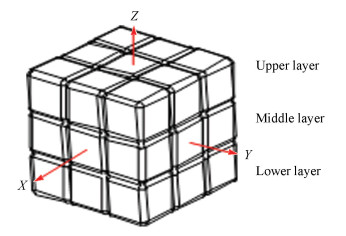
2 Description of Topological Configuration of the Three-Order RC 2.1 Expression of Single Layer Rotation Process of the RC MechanismThe RC mechanism is different from the traditional common mechanism. The connection between multiple components and special components enables the RC mechanism to have the characteristic of variable degree of freedom. A coordinate frame was set up at the center of the RC, as shown in Fig. 1. The movement process of the RC was simplified as a single rotation around a fixed axis according to the physical rotation properties of the RC mechanism, and the rotation of the other layers was essentially equivalent to the single rotation around a fixed axis. The following provisions make a convenient description:
|
Fig.1 Coordinate system and layer classification of the RC |
1) When the RC was in the state shown in Fig. 1, the connection between the center of the RC and the center of the central block of each face was defined as the outer normal, and this direction from the center of the RC to the center of the central block of each face was defined as the outer normal direction. Thus the direction of the outer normal line of the cube was reference direction.
2) According to the right-hand screw rule, the forward and backward operations for single layer rotation of the RC mechanism were set up. The rotating process of a single layer around a certain axis by 90° was called single step rotation.
3) According to the physical structure of the RC, it was divided into upper, middle, and lower layers in the direction of Z-axis, as shown in Fig. 1. The upper, middle, and lower layers of the X- andY-axis can be done in the same manner.
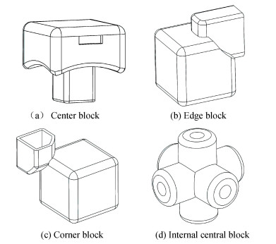
4) The twenty-six solid pieces of the RC were divided into three types: center block, edge block, and corner block. The cross at the geometric center of the RC was defined as the internal central block, as shown in Fig. 2.
|
Fig.2 The center block, edge block, corner block, and internal central block of the RC |
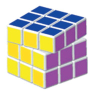
5) When the rotation angle of a single layer around a certain axis was between 0° and 90°, the RC was in a non-initial state, as shown in Fig. 3.
|
Fig.3 Rotation angle no greater than 90° |
The single forward rotation process for the upper part of RC around the Z-axis was analyzed. The upper part of the Z-axis of the cube was rotated forward to the Z-axis no more than 90°. After the rotation, the position of center block in the upper layer did not change relative to the position of the internal central block of the middle layer. The positions of the four corner blocks and the four edge blocks in the upper layer were changed relative to the positions of that in the middle layer. However, there was a fixed constraint relation between the position change of four edge blocks in the upper layer relative to the blocks in the middle layer and that of the four corner blocks relative to the blocks in the middle layer. The constraint relation was determined by the physical structure of the upper layer. According to the structural characteristics of the overall rotation when the upper layer rotated continuously, the four blocks in the rotation layer were considered as the over constrained components. In this way, for single forward rotation for the upper part of RC around the Z-axis, we just need to study the position relationship between the four corner blocks and center block in the upper layer and four corner blocks and four edge blocks in the middle layer, as well as the inner central block during the rotation of the three order RC. Thus the topological configuration of the RC rotation can be fully represented.
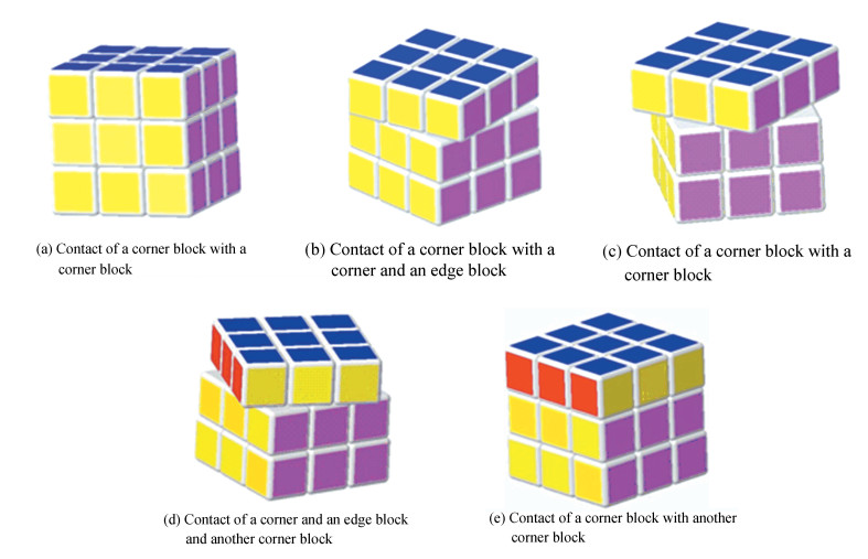
2.2 Adjacency Matrix Structure for Topological Configuration of the Rotation around a Fixed Axis of the RCTaking the upper layer rotating around the Z-axis as an example, the contact relationship of blocks between the upper layer and the middle layer was constantly changing during the overall rotation of the upper layer. During the ninety degree rotation of the upper layer of the RC, the connection relationship between the upper four corner blocks and the middle blocks had five states (as shown in Fig. 4): the contact of a corner block with a corner block, the contact of a corner block with a corner and an edge block, the contact of a corner block with a corner block, an edge block and another corner block, the contact of a corner and an edge block and another corner block, the contact of a corner block with another corner block. After 90° rotation, the cube returned to its initial state. It should be noted that according to any structure mode of the structural characteristics of the RC, the center block in the upper layer and the internal central block in the middle layer are directly connected through the central axis of the cross, so they are always in contact.
|
Fig.4 Five configurations of the upper layer |
The upper blocks were numbered 1, 2, 3, 4, and 5, where 1, 2, 3, and 4 were the upper corner blocks. The position of them was equivalent, and the numbering initial position could be arbitrarily defined. 5 was the upper center block. The middle blocks were numbered 1', 2', 3', 4', 5', 6', 7', 8', and 9', where 1', 3', 5', and 7' were corner blocks, each had an equivalent position, and the numbering initial position could be arbitrarily defined. 2', 4', 6', and 8' were edge blocks. Each edge block had an equivalent position, and 9' was an internal central block. According to the connection relationship between the upper four corner blocks and the upper center block with the middle blocks in the rotation process of the RC, the adjacency matrix of the contact relationship was constructed using the method of topology[17] and graph theory[18]. The contact relationship matrix of five rows and nine columns can be listed.
If the cube is forwarded to the Z-axis for a single operation, and if the upper block and the lower block are in contact, the connection relationship between the two adjacent blocks is represented by 1, it is represented by 0 without contact, and then the adjacency matrix can be defined as:
| $ {\mathit{\boldsymbol{A}}_{KL}} = {({\mathit{\boldsymbol{m}}_{ij}})_{i \times j}},i = 1,2,3,4,5;j = 1,2, \cdots ,9 $ | (1) |
In the formula, K is the rotation axis when rotating, and L represents the rotating layer of the upper, middle, and lower layer. If mij=1, i is in contact with j; if mij=0, i and j are not in contact.
According to Eq. (1), the adjacency matrix of configuration a can be obtained, which means the adjacency matrix AZU in the initial state along the upper part of the Z-axis is:
| $ \begin{array}{l} \ \ \ \ \ {\kern 1pt} {\kern 1pt} {\kern 1pt} {\kern 1pt} {\kern 1pt} {\kern 1pt} {\kern 1pt} {\kern 1pt} {\kern 1pt} {\kern 1pt} {\kern 1pt} {\kern 1pt} {\kern 1pt} {\kern 1pt} {\kern 1pt} {\kern 1pt} {\kern 1pt} {\kern 1pt} {\kern 1pt} {\kern 1pt} {\kern 1pt} {\kern 1pt} {\kern 1pt} {\kern 1pt} {\kern 1pt} {\kern 1pt} {\kern 1pt} {\kern 1pt} {\kern 1pt} {\kern 1pt} {\kern 1pt} {\kern 1pt} \begin{array}{*{20}{l}} {{\kern 1pt} {1^\prime }}&{{2^\prime }}&{{3^\prime }}&{{4^\prime }}&{{5^\prime }}&{{6^\prime }}&{{7^\prime }}&{{8^\prime }}&{{9^\prime }} \end{array}\\ {\mathit{\boldsymbol{A}}_{{\rm{ZU}}}} = \left[ {\begin{array}{*{20}{c}} 1&\ 0&\ 0&\ 0&\ 0&\ 0&\ 0&\ 0&\ 1\\ 0&\ 0&\ 1&\ 0&\ 0&\ 0&\ 0&\ 0&\ 1\\ 0&\ 0&\ 0&\ 0&\ 1&\ 0&\ 0&\ 0&\ 1\\ 0&\ 0&\ 0&\ 0&\ 0&\ 0&\ 1&\ 0&\ 1\\ 0&\ 0&\ 0&\ 0&\ 0&\ 0&\ 0&\ 0&\ 1 \end{array}} \right]\begin{array}{*{20}{l}} 1\\ 2\\ 3\\ 4\\ 5 \end{array} \end{array} $ |
Similarly, the adjacency matrices of topological configurations b, c, d and e are:
| $ {\mathit{\boldsymbol{A}}^\prime }_{{\rm{ZU}}} = \left[ {\begin{array}{*{20}{c}} 1&1&0&0&0&0&0&0&1\\ 0&0&1&1&0&0&0&0&1\\ 0&0&0&0&1&1&0&0&1\\ 0&0&0&0&0&0&1&1&1\\ 0&0&0&0&0&0&0&0&1 \end{array}} \right] $ |
| $ {\mathit{\boldsymbol{A}}^{\prime \prime }}_{{\rm{ZU}}} = \left[ {\begin{array}{*{20}{l}} 1&1&1&0&0&0&0&0&1\\ 0&0&1&1&1&0&0&0&1\\ 0&0&0&0&1&1&1&0&1\\ 1&0&0&0&0&0&1&1&1\\ 0&0&0&0&0&0&0&0&1 \end{array}} \right] $ |
| $ {\mathit{\boldsymbol{A}}^{\prime \prime \prime }}_{{\rm{ZU}}} = \left[ {\begin{array}{*{20}{c}} 0&1&1&0&0&0&0&0&1\\ 0&0&0&1&1&0&0&0&1\\ 0&0&0&0&0&1&1&0&1\\ 1&0&0&0&0&0&0&1&1\\ 0&0&0&0&0&0&0&0&1 \end{array}} \right] $ |
| $ {\mathit{\boldsymbol{A}}^{\prime \prime \prime \prime }}_{{\rm{ZU}}} = \left[ {\begin{array}{*{20}{l}} 0&0&1&0&0&0&0&0&1\\ 0&0&0&0&1&0&0&0&1\\ 0&0&0&0&0&0&1&0&1\\ 1&0&0&0&0&0&0&0&1\\ 0&0&0&0&0&0&0&0&1 \end{array}} \right] $ |
It is not difficult to find from the adjacency matrix of each configuration that there is regular contact and separation among the blocks in the whole process with the rotation of the upper layer of the cube.
Similarly, the adjacency matrix A ZD under the initial state of the lower layer of Z-axis is:
| $ {\mathit{\boldsymbol{A}}_{{\rm{ZD}}}} = \left[ {\begin{array}{*{20}{c}} 1&0&0&0&0&0&0&0&1\\ 0&0&1&0&0&0&0&0&1\\ 0&0&0&0&1&0&0&0&1\\ 0&0&0&0&0&0&1&0&1\\ 0&0&0&0&0&0&0&0&1 \end{array}} \right] $ |
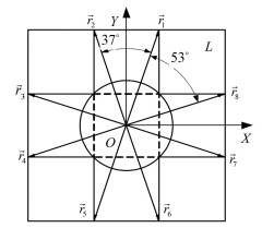
The adjacency matrix of the topological configuration is an abstract representation to the rotation process of the RC. The continuous analysis of the adjacency matrix transformation was performed as follows. The length of each small cubicle is l, the vertex of adjacent blocks touching each other on the edge is the vector end point, and eight vectors were established in the upper layer to describe the position of each block (as shown in Fig. 5), which are represented by
|
Fig.5 Vector graphics of the upper layer |
The vector coordinates of the upper layer are as follows:
| $ \left\{ {\begin{array}{*{20}{l}} {{{\mathit{\boldsymbol{\vec r}}}_1} = (0.5l,1.5l),\quad {{\mathit{\boldsymbol{\vec r}}}_2} = ( - 0.5l,1.5l)}\\ {{{\mathit{\boldsymbol{\vec r}}}_3} = ( - 1.5l,0.5l),{{\mathit{\boldsymbol{\vec r}}}_4} = ( - 1.5l, - 0.5l)}\\ {{{\mathit{\boldsymbol{\vec r}}}_5} = ( - 0.5l, - 1.5l),{{\mathit{\boldsymbol{\vec r}}}_6} = (0.5l, - 1.5l)}\\ {{{\mathit{\boldsymbol{\vec r}}}_7} = (1.5l, - 0.5l),\quad {{\mathit{\boldsymbol{\vec r}}}_8} = (1.5l,0.5l)} \end{array}} \right. $ | (2) |
The rotation in the upper layer of the cube can be represented by the rotation of the established vector. The rotation position of each block is represented by the two vectors from the origin to the two vertices. The upper rotation of the cube is the rotation of the vector
| $ {\theta _1} = {\rm{arccos}}\frac{{\frac{5}{2}{l^2} + \frac{5}{2}{l^2} - 2{l^2}}}{{2 \times \frac{5}{2}{l^2}}} \approx {53^\circ } $ |
As shown in Fig. 5, the angle between
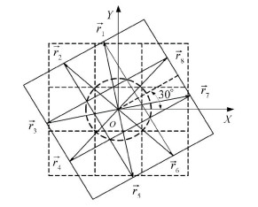
|
Fig.6 Rotation diagram of the upper layer |
The change of topological structure is also the change of the contact relationship between the two blocks with relative motion, expressed by the rotation angle α. Referring to Fig. 6, the rotation angles α corresponding to the five configuration states a, b, c, d, and e are shown in Table 1.
| Table 1 Angles of five configuration states |
The rotation matrix of the vector was set up as follows:
| $ {\mathit{\boldsymbol{\vec r}}_i} = \left( {\begin{array}{*{20}{c}} {{\rm{cos}}\alpha }&{ - {\rm{sin}}\alpha }\\ {{\rm{sin}}\alpha }&{{\rm{cos}}\alpha } \end{array}} \right)\left( {\begin{array}{*{20}{l}} {{r_{ix}}}\\ {{r_{iy}}} \end{array}} \right) $ | (3) |
In Eq. (3), i=1, 2, 3, …, 8.
It can be seen from Eq. (3) that the change of the rotational position of the cube is the change of the rotation angle. When the rotation angle is determined, the position of the vector representing the position of the RC is determined, and the topological structure of the cube at the position is determined.
It can be seen from the above analysis that in the process of one operation of the RC, there is a clear relationship between the change of topological structure and its structural size, and the mutation of the topological structure is determined by the combination of its structural size and rotation angle.
In this section, the topological configuration of the third-order RC mechanism was described. The adjacency matrix was used to describe the state of the RC in the single-layer rotation process, and the angular ranges of the five configurations in the rotation process were given.
3 Degree of Freedom Analysis of the RC 3.1 Construction of Topology Adjacency MatricesIn the process of RC rotation, the state reached by the RC when the middle layer rotates alone is equivalent to that when the middle layer of RC does not rotate but both upper and lower layers rotate simultaneously. The state after the upper, middle, and lower layers rotate is expressed by adjacency matrix, AZU, AZM, and AZD, respectively. The topological adjacency matrix in the initial state of the Z-axis middle layer is the union of the Z-axis upper layer topological adjacency matrix and the lower layer topological adjacency matrix, which is defined as:
| $ {\mathit{\boldsymbol{A}}_{{\rm{ZM}}}} = {\mathit{\boldsymbol{A}}_{{\rm{ZU}}}} \cup {\mathit{\boldsymbol{A}}_{{\rm{ZD}}}} $ | (4) |
According to the construction mode of the Z-axis three-layer topological adjacency matrix, the topological adjacency matrices of the three layers of the X- and Y-axis in the initial state can be constructed as
If expanded to other axis directions, the set of topology adjacency matrices of the RC in the initial state is MN, which can be expressed as:
| $ {\mathit{\boldsymbol{M}}_{\rm{N}}} = ({\mathit{\boldsymbol{A}}_{{\rm{NU}}}},{\mathit{\boldsymbol{A}}_{{\rm{NM}}}},{\mathit{\boldsymbol{A}}_{{\rm{ND}}}}),N = X,Y,Z $ | (5) |
Furthermore, if the set of topology adjacency matrices of the cube in the initial state is M , then it can be expressed as:
| $ \mathit{\boldsymbol{M}} = ({M_X},{M_Y},{M_Z}) $ | (6) |
From Eqs. (5)-(6), there are nine elements for M , which define topological structure of the cube in the initial state. When the cube rotates around a coordinate axis, the topology adjacent matrices under the other two axes will not be able to form a matrix with 5-row and 9-column, which is defined as an element O. Taking an infinitesimal angle of the upper Z-axis as an example, the set of topological adjacency matrix of the cube in the initial state is:
| $ \mathit{\boldsymbol{U}} = (O,O,O,O,O,O,{M_Z}) $ | (7) |
Similarly, taking it as an example that an infinitesimal angle can be rotated by the upper layer of the X- or Y-axis, the set of the topological adjacency matrix of the cube in the initial state is:
| $ {\mathit{\boldsymbol{V}} = ({M_X},O,O,O,O,O,O)} $ | (8) |
| $ {\mathit{\boldsymbol{W}} = (O,O,O,{M_Y},O,O,O)} $ | (9) |
Obviously,
There is a coupling relationship in the structure of the RC, which shows the characteristics of a lot of changes of degrees of freedom and difficulty in description. In order to describe this characteristic, relieving this coupling relationship was considered, and the concept of entanglement degree of freedom is proposed as follows: the entanglement degree of the mechanism is the number of non-zero elements in the adjacency matrix of the overall topological structure after an infinitesimal displacement of a movable component of the mechanism in the initial state.
It is known from the definition that the nature of the entanglement degree of freedom is the number of components which has the possibility of motion after an infinitesimal displacement of a movable component.
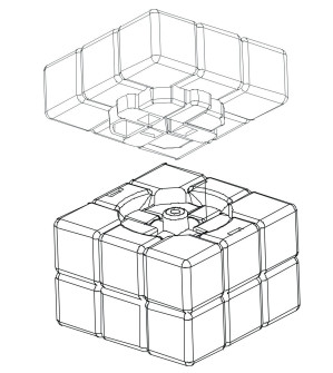
As shown in Fig. 7, the RC center is a combination of multiple parts that are tightly combined into a mutually constrained movement, where a single component is shared by three revolute pairs in the initial state, and nine corners on a facet form a revolute pair when rotating. At this point each corner is owned by the revolute pair and not by the other two revolute pairs, which is manifested in that the rotation of the corner block is not a single rotation of the block, and the rotation of each block of the cube is subordinate to the rotation of the entire surface, and the degrees of freedom are uniform at this time. Thus nine blocks form a face, and one face has a revolute pair. When a certain surface rotates, the remaining four faces with the common edge of the face will not be able to rotate, which is the core reason for the recombination and variable degree of the freedom of the RC.
|
Fig.7 Single layer rotation diagram of RC |
When an infinitesimal rotation angle occurs in one layer of the cube, the adjacency matrix of the layer and the adjacent layer changes, and the four faces having a common edge with the surface no longer form an adjacency matrix. The nine elements in the adjacent matrix M of topological structure of the cube in the initial state are all changed. According to the definition of entanglement degrees of freedom, the degrees of freedom in any state of the cube can be found.
3.3 Analysis of RC Degree of Freedom under Definition of Entangled Degree of FreedomEq. (6) shows that the set of the adjacency matrix M of the topological structure of the RC in the initial state was composed of MX, MY, and MZ. If two elements A1, A2, are selected from the three subsets, only one element is allowed to be selected in each subset, i.e.:
| $ {{A_1},{A_2} \in \mathit{\boldsymbol{M}}} $ | (10a) |
| $ {{A_1} \in {M_j};j = X,Y,Z} $ | (10b) |
| $ {{A_2} \in {M_k};k = X,Y,Z} $ | (10c) |
| $ {j \ne k} $ | (10d) |
Eq. (10) shows that a slight rotation occurs on the surface represented by the selected element, i.e., a slight rotation occurs on the two surfaces perpendicular to each other in the optional space. The cube is unable to rotate at this time, i.e., this adds two driving forces to the entire mechanism of cube at the same time. At this time, the motion form of each layer of the RC is determined. So the whole cube becomes a rigid body, and no movement can be done. At this time, the entanglement degree of the cube mechanism is 2, and the movable member is the two layers of the added drive.
If one element A is selected from the set of the adjacency matrix M of the topological structure of the RC in the initial state, it can be expressed as below:
| $ \begin{array}{*{20}{l}} {{\kern 1pt} {\kern 1pt} {\kern 1pt} {\kern 1pt} {\kern 1pt} {\kern 1pt} {\kern 1pt} {\kern 1pt} {\kern 1pt} {\kern 1pt} {\kern 1pt} {\kern 1pt} {\kern 1pt} {\kern 1pt} {\kern 1pt} {\kern 1pt} {\kern 1pt} {\kern 1pt} {\kern 1pt} {\kern 1pt} {\kern 1pt} {\kern 1pt} {\kern 1pt} {\kern 1pt} {\kern 1pt} {\kern 1pt} {\kern 1pt} {\kern 1pt} A \in \mathit{\boldsymbol{M}}}\\ {A \in {M_j},j = X,Y,Z} \end{array} $ | (11) |
Eq. (11) shows that a slight rotation occurs on the surface represented by the selected element, and the cube will rotate around the fixed axis. From Eqs. (7)-(9), the set of the adjacency matrix of the topological structure of the cube is one of three sets U, V, W, with three elements. It can be known from the definition of the entanglement degree of the mechanism that the entanglement degree is 3, i.e., there are three layers that can move independently although the RC mechanism has three movable layers at this time. Eq. (4) shows that the motion of the middle layer can be represented by the motion of the upper layer and lower layer. The independent motion of the cube has 3 layers, the number of layers with kinematic independence is only 2 according to the equivalence of the motion result.
The number of independent layers in kinematics is the basis for judging the optimal loading of the driving force of the RC mechanism. Thus the least quantity of drivers is supplied according to the quantity of degree of freedom with kinematic independence of the cube, so the RC mechanism as a whole will have a complete movement.
As shown in Fig. 1, the cube itself has three completely independent axes, and each axis can independently derive three independently rotatable layers and two degree of freedom with kinematic independence from Eq. (11). So for the whole RC, the number of layers that can move independently is the number 9 of all elements from set M in Eq. (6), but the number of layers with kinematic independence is 6.
In this section, the degree of freedom of RC mechanism was analyzed with adjacency matrix. The concept of the degree of freedom of RC entanglement was defined, and the expression method of the degree of freedom of RC under the degree of freedom of entanglement was given.
4 Prime Representation in Rotation Process of Three-Order RC 4.1 Prime Numbering MethodFrom the basic theorem of arithmetic, any natural number greater than 1 can be decomposed into the product of some prime numbers, and in the case of no order, this decomposition is unique, i.e., the result of multiplication of prime numbers is unique. This theorem was used as the basis for the determination of the rotation of the cube.
The three-order cube layer is defined as follows: the cube includes six opposite layers, namely, the upper layer, the lower layer, the left layer, the right layer, the front layer, and the back layer, which are represented by letters U, D, L, R, F, and B, respectively.
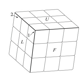
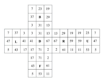
Regardless of the color of the cube, the whole cube is considered a mechanism, and each block of the cube is different. This difference is manifested by different prime numbers. For the different facets of the same block, the same prime number was marked, and different blocks were marked with different prime numbers, with the position shown in Fig. 8 as the initial position. The selected prime numbers and layer codes were distributed in the cube expansion map as shown in Fig. 9.
|
Fig.8 Schematic diagram of the three-order RC in the initial position |
|
Fig.9 Prime number distribution in the RC expansion map |
4.2 RC Rotation Judgment Method
The recognition of RC rotation needs to solve three problems: the determination of the Rubik's rotation layer and the rotation axis, and whether the layer is forward or reverse.
Due to the physical structure of the RC, any two layers with a common edge cannot rotate at the same time, i.e., if any two faces of the RC with a common edge are fixed, the whole RC will become a rigid body and cannot make any movements. The prime information, which is carried by the block on the three edges from any one of the eight vertices of the RC, can completely represent all the information of the RC. When two adjacent faces with the same edge are selected and the prime number information of the three edges from any corner of the common edge (which means edge block of the cube) is checked, the rotation of the RC can be known by comparative analysis.
As shown in Figs. 8-9, if the L-face and the U-face of the cube are selected and the prime number information on them is checked, the corner block 1 and the corner block 2 satisfy the above checking requirements. Taking the corner block 1 as an example to explain the checking method, the three edges, which are marked with black line in the Fig. 8, are the selected edges, and the prime number information on the block is shown in Fig. 9.
The method of judgment is as follows:
Step 1 The prime numbers of the edge block on each side marked with the black line were multiplied by the prime numbers on the adjacent corner blocks. Three sets of data were obtained because there were three sides, and the edges on the three sides were considered as the reference. The multiply order followed up and down, left and right, and before and after. The prime product was stored in the array in turn. For example, for the intersection of the U layer and the L layer as shown in Fig. 8, the following sequence was performed: first the prime number on the edge block was multiplied by the prime number on the corner block 1, and then was multiplied by the prime number on the edge block and the prime numbers on the corner blocks 2.
Step 2 After the cube layer was rotated, the same operation was performed to obtain the other three sets of data.
Step 3 The two sets of data were compared and analyzed to determine which cube layer was rotating.
Step 4 According to the judgment result of the previous step, the method of judging the clockwise and anticlockwise rotation of the rotating layer is described as follows: the rotating layer and only one side of the selected three sides intersected, the intersection point was one corner block on the three sides (four corner blocks on the three sides), the corner block was in the selected checking face (the checking faces were U face and F face in this case) and was opposite to another corner block in the rotating layer. The prime number information on the corner block was captured by using the sensor. Then the prime number was used to multiply the prime number intersected on the edge of the side. If the product is the same as one of the above set of data (the prime product is unique), then the layer is in rotating state. If it is not in the above set of data, it is another rotation state.
A unified mathematical description of the above expressions is as follows:
1) The prime product of the three selected edges of the cube in the initial state was recorded in the array Aij. i=1, 2, 3 represents the set of data, and j=1, 2 represents the number in the i set of data.
2) The prime product information of the three sides after the cube was rotated in the array Gmn was recorded. The meaning of m and I was the same, so was n and j.
3) Record
4) Using the fourth step method to determine how the rotating layer rotates, i.e., clockwise or counterclockwise, is not described here.
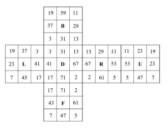
4.3 A Rotation Example of the RCThe above selected detection facet was taken as an example for illustration. The prime number distribution in the initial position is shown in Fig. 9. The prime number distribution when the upper part of the RC was rotated counterclockwise once is shown in Fig. 10.
|
Fig.10 Prime number distribution after the counter clockwise rotation of the RC |
1) At the beginning:
2) After rotation:
3) Comparison of the above two sets of data
4) According to the judgment method in the fourth step, the detected prime number was 19, and the data required to be judged was 23×19.
In this section, the process of RC rotation using the method of prime number label was presented, the judgment process of RC rotation based on prime number was given, and an example of judgment of RC rotation based on the expansion diagram of RC with prime number label was explained.
5 Conclusions1) An adjacency matrix of contact relation in single layer rotation of RC was constructed based on the method of topology and graph theory, and the transformation rules of five configurations were analyzed.
2) The concept of entanglement degree of freedom was proposed, and the set of adjacency matrix was set up. The degree of freedom of the RC was determined in any shape by finding the number of non-zero elements in the set of adjacency matrix, and the degree of freedom of the RC was described.
3) A method of using prime number to represent RC rotation was proposed. This method is concise in calculation and appropriate for computer processing.
| [1] |
Zeng D X, Li M, Wang J J, et al. Overview of Rubik's Cube and reflections on its application in mechanism. Chinese Journal of Mechanical Engineering, 2018, 31: 9-20. DOI:10.1186/s10033-018-0269-7 (  0) 0) |
| [2] |
Zhao B H, Gao S Y, Zhang J N, et al. Rubik's Cube type deep space exploration aircraft. Technology Innovation and Application, 2014(24): 61-63. (in Chinese) (  0) 0) |
| [3] |
Li S C. The Science and Culture in Rubik's Cube. Beijing: Higher Education Press, 2015: 10-12. (in Chinese)
(  0) 0) |
| [4] |
Zeng D X, Li M, Wang J J, et al. Analysis of structural composition and representation of topological structures of Rubik's Cube mechanism. Mechanism and Machine Theory, 2019. (  0) 0) |
| [5] |
Zhao C, Guo H W, Deng Z Q, et al. Structure design and performance evaluation of variable configuration truss-type satellite platform. Journal of Harbin Institute of Technology, 2018, 50(1): 11-17. (in Chinese) DOI:10.11918/j.issn.0367-6234.201610032 (  0) 0) |
| [6] |
Dai J S, Jones J R. Mobility in metamorphic mechanisms of foldable erectable kinds. Journal of Mechanical Design, 1999, 121(3): 375-382. DOI:10.1115/1.2829470 (  0) 0) |
| [7] |
Wang C, Xu J J. An algorithm for finding the three-dimension paths of the S-shaped intellectual magic square. Software Design and Development, 2008, 1(4): 686-690. (in Chinese) (  0) 0) |
| [8] |
Dai J S, Zhang Q X. Metamorphic mechanisms and their configuration models. Chinese Journal of Mechanical Engineering, 2000, 13(3): 212-218. DOI:10.3901/CJME.2000.03.212 (  0) 0) |
| [9] |
Dai J S, Ding X L, Wang D L. Topological changes and the corresponding matrix operations of a spatial metamorphic mechanism. Chinese Journal of Mechanical Engineering, 2005, 41(8): 30-35. (in Chinese) DOI:10.3901/JME.2005.08.030 (  0) 0) |
| [10] |
Dai J S, Jones J R. Matrix representation of topological changes in metamorphic mechanisms. ASME Transactions, Journal of Mechanical Design, 2005, 127(7): 837-840. DOI:10.1115/1.1866159 (  0) 0) |
| [11] |
Bai P, Sun L B, Liang G. A new matrix expression method for whole information to describe and analyze a metamorphic mechanism. Mechanical Science and Technology, 2017, 36(4): 553-559. (in Chinese) DOI:10.13433/j.cnki.1003-8728.2017.0410 (  0) 0) |
| [12] |
Yu H Y, Zeng C Y, Guo Z. Type synthesis method of lower-mobility metamorphic parallel mechanism. Journal of Harbin Institute of Technology, 2018, 50(1): 42-49. (in Chinese) DOI:10.11918/j.issn.0367-6234.201703071 (  0) 0) |
| [13] |
Tian H B, Ma H W, Ma K. Method for configuration synthesis of metamorphic mechanisms based on functional analyses. Mechanism and Machine Theory, 2018, 123: 27-39. DOI:10.1016/j.mechmachtheory.2018.01.009 (  0) 0) |
| [14] |
Liu X D. Structural Analysis and Synthesis of Parallel Metamorphic Mechanisms. Beijing: Beijing University of Posts and Telecommunications, 2017. (in Chinese)
(  0) 0) |
| [15] |
Wang B, Fang Y F. Type synthesis of metamorphic parallel mechanism with spherical five. Journal of Mechanical Engineering, 2018, 54(19): 18-26. (in Chinese) DOI:10.3901/JME.2018.19.018 (  0) 0) |
| [16] |
Zhen W K, Kang X, Zhang X S, et al. Gait planning of a novel metamorphic quadruped robot. Journal of Mechanical Engineering, 2016, 52(11): 26-33. DOI:10.3901/JME.2016.11.026.(inChinses) (  0) 0) |
| [17] |
Wu T, Zhang W X, Ding X L. Design and analysis of a novel parallel metamorphic mechanism. Journal of Mechanical Engineering, 2015, 51(7): 30-37. (in Chinese) DOI:10.3901/JME.2015.07.030 (  0) 0) |
| [18] |
Dai J S, Li D L, Zhang Q X, et al. Mobility analysis of a complex structured ball based on mechanism decomposition and equivalent screw system analysis. Mechanism and Machine Theory, 2004, 39(4): 445-458. DOI:10.1016/j.mechmachtheory.2003.12.004 (  0) 0) |
| [19] |
Yang T L, Shen H P, Liu A X, et al. Review of the formulas for degrees of freedom in the past ten years. Journal of Mechanical Engineering, 2015, 51(13): 69-80. (in Chinese) DOI:10.3901/JME.2015.13.069 (  0) 0) |
| [20] |
Guo Z H, Ma L Z, Yang Q Z. Topological type analysis of the variable freedom mechanism based on the metamorphic principle. China Mechanical Engineering, 2005, 16(1): 1-3, 7. (in Chinese) (  0) 0) |
 2020, Vol. 27


