Tensegrity structures are composed of flexible strings and rigid bars[1-3] that deliver any external force or torque to internal member force in the form of torsional or compressional forces[4-5]. Strings in tensegrity structures withstand the torsional internal force that always directs along the strings axis, while bars experience a compressional internal force that always directs along the bars axis[6-7]. Tensegrity structures possess a property which assures that the shape of the tensegrity can be changed with little changes in the potential energy of the structure[8-9]. Since six bar tensegrity ball structure is symmetric in motion in hexagonal packing, nodes and members can be divided into categories by the same dynamics[10-11]. With the properties of being deployable and tunable, tensegrity structures can easily change shapes under the provision of some external force or torque, therefore they are considered the most suitable to be utilized in tough environmental conditions and for space exploring missions[8, 12-13]. Six bar tensegrity ball robots can be packed, separated, and launched easily without any hazard to the payload, and thus have been applied experimentally for the exploration of other planets by NASA[14-16]. Zhang et al.[17]conducted drop tests of three different modular tensegrity lattice systems of a six bar tensegrity ball robot to analyze the impact of resistance in landing. They found that lattice is not enough as a structural solution that strut material should also be considered and the landing of the robot on two vertical bars is more effective in protecting the payload. The investigation of symmetric motion in different members of the structure in compression and expansion is essential for packing, landing, rolling, and moving the six bar ball tensegrity structure for exploring planetary missions. However, there is no study that has demonstrated the dynamic symmetry in different members of six bar tensegrity structure and the effect of external force on structure in compression and expansion processes.
In this paper, the dynamic symmetry of compression and expansion processes was analyzed in six bar tensegrity ball structure with the application of external force which changes the positions of members and nodes and deforms the structure. A comparative analysis of compression and expansion processes was performed to assure the processes following the motion laws and the deformation of the structure. The paper aims to investigate different members (either flexible or rigid) that obey same laws of motion and experience same movement with the study of deformation velocity, displacement, momentum, and deformation in compression and expansion. Direct and indirect effects of external force on different members of six bar tensegrity structure were analyzed. The relationship between external force and force densities of different members in compression and expansion was also formulated in this study on an assumption basis.
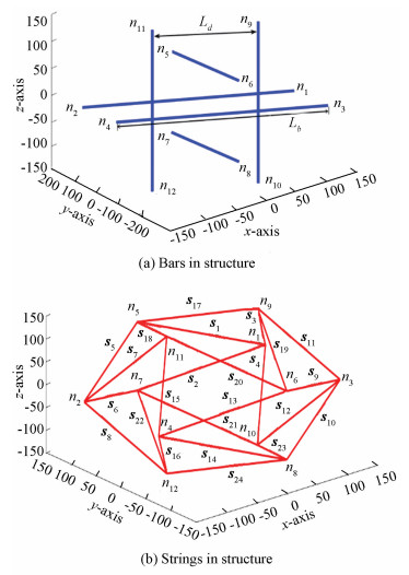
2 Defining the Tensegrity StructureSix bar tensegrity ball structure is a highly symmetrical structure containing 12 rigid compressive bars and 24 flexible strings in tension[18](Fig. 1). Each bar length is Lb and displayed by thick lines, and each string length is Ls shown by thin lines. All parallel bars have the same distance Ld.

|
Fig.1 Six bar tensegrity ball structure |
The six bar tensegrity ball structure has 12 nodes and a node ni, which can be represented in Cartesian coordinates as
| $ {n_i} = ({n_{ix}}\quad {n_{iy}}\quad {n_{iz}}),i \in (1, \cdots ,12) $ |
Node matrix can be written by arranging all nodes along columns as
| $ \mathit{\boldsymbol{N}} = {[{n_1}{\kern 1pt} {\kern 1pt} {\kern 1pt} {n_2}{\kern 1pt} {\kern 1pt} {\kern 1pt} {\kern 1pt} \cdots {\kern 1pt} {\kern 1pt} {\kern 1pt} {\kern 1pt} {n_{12}}]_{3 \times 12}} $ |
All members of the structure are connected by two nodes and shape the structure as a self-balanced structure. Every member can be described by two of end nodes that it is linked with. Here, members are represented by node vectors. There are six bars in the structure (Fig. 2(a)), and bar bi (i bar vector) can be described by a node vector that starts from nj and ends at nk as follows:
|
Fig.2 Strings and bars in six bar tensegrity ball structure |
| $ {\mathit{\boldsymbol{b}}_i} = \left[ {\begin{array}{*{20}{l}} {{\mathit{\boldsymbol{b}}_{ix}}}\\ {{\mathit{\boldsymbol{b}}_{iy}}}\\ {{\mathit{\boldsymbol{b}}_{iz}}} \end{array}} \right] = {n_k} - {n_j} = \left[ {\begin{array}{*{20}{l}} {{n_{kx}} - {n_{jx}}}\\ {{n_{ky}} - {n_{jy}}}\\ {{n_{kz}} - {n_{jz}}} \end{array}} \right] $ |
where, i∈(1, …, 6) and k, j∈(1, …, 12).
Bar matrix can be described by arranging bars along columns as
| $ \mathit{\boldsymbol{B}} = {[{\mathit{\boldsymbol{b}}_1}{\kern 1pt} {\kern 1pt} {\kern 1pt} {\mathit{\boldsymbol{b}}_2}{\kern 1pt} {\kern 1pt} {\kern 1pt} {\kern 1pt} \cdots {\kern 1pt} {\kern 1pt} {\kern 1pt} {\kern 1pt} {\mathit{\boldsymbol{b}}_6}]_{3 \times 6}} $ |
The structure has 24 flexible strings (Fig. 2(b)), and string si (i string vector) can be described by a node vector that starts from np and ends at nq as follows:
| $ {\mathit{\boldsymbol{s}}_\mathit{\boldsymbol{i}}} = \left[ {\begin{array}{*{20}{l}} {{\mathit{\boldsymbol{s}}_{ix}}}\\ {{\mathit{\boldsymbol{s}}_{iy}}}\\ {{\mathit{\boldsymbol{s}}_{iz}}} \end{array}} \right] = {n_q} - {n_p} = \left[ {\begin{array}{*{20}{l}} {{n_{qx}} - {n_{px}}}\\ {{n_{qy}} - {n_{py}}}\\ {{n_{qz}} - {n_{pz}}} \end{array}} \right] $ |
where, i∈(1, …, 24) and p, q∈(1, …, 12).
String matrix can be defined by arranging all strings along columns as
| $ \mathit{\boldsymbol{S}} = {[{\mathit{\boldsymbol{s}}_1}{\kern 1pt} {\kern 1pt} {\kern 1pt} {\mathit{\boldsymbol{s}}_2}{\kern 1pt} {\kern 1pt} {\kern 1pt} {\kern 1pt} \cdots {\kern 1pt} {\kern 1pt} {\kern 1pt} {\kern 1pt} {\mathit{\boldsymbol{s}}_{24}}]_{3 \times 24}} $ |
An analytical approach was adopted to find out the relationship between external force and members force densities in compression and expansion of the structure.
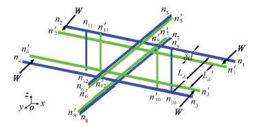
3.1 Relationship between External Force and Force Densities in CompressionIf equal and opposite external force W is applied along y-axis on nodes n1, n2, n3, and n4 of two parallel bars b1 and b2 lying on the xoy plane (Fig. 3), it will compress the structure and relocate all nodes and members from n to n', because all nodes and members are interconnected with each other. An external force that acts in the inward direction squeezed the structure and reduced the distance Ld by δd to a new distance Ld', and equal compression was assumed along all axes. Eq.(1) displays new coordinates of the structure in compression.
|
Fig.3 Compressing the structure by external force along one plane |
| $ \begin{array}{l} {\kern 1pt} {\kern 1pt} {\kern 1pt} {\kern 1pt} {\kern 1pt} {\kern 1pt} {\kern 1pt} {\kern 1pt} {\kern 1pt} {\kern 1pt} {\kern 1pt} {\kern 1pt} {\kern 1pt} {\kern 1pt} {\kern 1pt} {\kern 1pt} {\kern 1pt} {\kern 1pt} {\kern 1pt} {\kern 1pt} {\kern 1pt} {\kern 1pt} {\kern 1pt} {\kern 1pt} {\kern 1pt} {\kern 1pt} {\kern 1pt} {\kern 1pt} \begin{array}{*{20}{c}} {\ \ \quad {n_1}^\prime }{\ \ \ \ \ \ \quad {n_2}^\prime }{\ \ \ \ \ \ \quad {n_3}^\prime }{\ \ \ \ \ \ \ \ \quad {n_4}^\prime }{\ \ \ \ \ \ \ \quad {n_5}^\prime }{\ \ \ \ \ \ \quad {n_6}^\prime }{\ \ \ \ \ \ \ \quad {n_7}^\prime }{\ \ \ \ \ \ \ \quad {n_8}^\prime }{\ \ \ \ \ \ \ \quad {n_9}^\prime }{\ \ \ \ \ \ \quad {n_{10}}^\prime }{\ \ \ \ \ \ \quad {n_{11}}^\prime }{\ \ \ \ \ \ \quad {n_{12}}^\prime } \end{array}\\ \mathit{\boldsymbol{N}} = \left[ {\begin{array}{*{20}{c}} {0.5{L_b}}&{ - 0.5{L_b}}&{0.5{L_b}}&{ - 0.5{L_b}}&0&0&0&0&{0.5L_d^\prime }&{0.5L_d^\prime }&{ - 0.5L_d^\prime }&{ - 0.5L_d^\prime }\\ {0.5L_d^\prime }&{0.5L_d^\prime }&{ - 0.5L_d^\prime }&{ - 0.5L_d^\prime }&{0.5{L_b}}&{ - 0.5{L_b}}&{0.5{L_b}}&{ - 0.5{L_b}}&0&0&0&0\\ 0&0&0&0&{0.5L_d^\prime }&{0.5L_d^\prime }&{ - 0.5L_d^\prime }&{ - 0.5L_d^\prime }&{0.5{L_b}}&{ - 0.5{L_b}}&{0.5{L_b}}&{ - 0.5{L_b}} \end{array}} \right] \\ \in {{\bf{R}}^{3 \times 12}} \end{array} $ | (1) |
n1', n2', n3', n4' are in xoy plane, n5', n6', n7', n8' are in yoz plane, and n9', n10', n11', n12' are in zox plane.The outer bars demonstrate when there is no external force acting on the structure, and inner bars lines show the structure in compression under the effect of external force W.
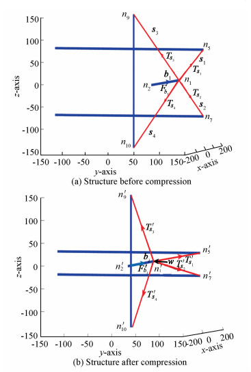
Fig. 4(a) shows the structure in a static position when there is no external force, and Fig. 4(b) presents the compressed structure when an external force W acts along the inward direction of the structure. To study the effect of the external force on the structure, node 1 (n1) was considered in calculation. Therefore, all forces acting on the node are
|
Fig.4 External force compressing the structure |
| $ \mathit{\boldsymbol{W}} + {\mathit{\boldsymbol{F}}_{{\mathit{\boldsymbol{b}}_1}}} + \mathit{\boldsymbol{T}}_{{\mathit{\boldsymbol{s}}_1}}^\prime + \mathit{\boldsymbol{T}}_{{\mathit{\boldsymbol{s}}_2}}^\prime + \mathit{\boldsymbol{T}}_{{\mathit{\boldsymbol{s}}_3}}^\prime + \mathit{\boldsymbol{T}}_{{\mathit{\boldsymbol{s}}_4}}^\prime = 0 $ |
where W is the external force applied on node n1, which changes the internal force of all members. Fb1 is the force applied by bar b1, and T's1, T's2, T's3 and T's4 are the forces applied by strings s1, s2, s3 and s4 in a compressed structure (Fig. 4(b)).Therefore,
| $ \begin{array}{l} \mathit{\boldsymbol{W}} + {\lambda ^\prime }(n_1^\prime - n_2^\prime ) + \gamma _1^\prime (n_5^\prime - n_1^\prime ) + \gamma _2^\prime (n_7^\prime - n_1^\prime ) + \\ {\kern 1pt} {\kern 1pt} {\kern 1pt} {\kern 1pt} {\kern 1pt} {\kern 1pt} {\kern 1pt} {\kern 1pt} {\kern 1pt} {\kern 1pt} {\kern 1pt} {\kern 1pt} {\kern 1pt} {\kern 1pt} {\kern 1pt} {\kern 1pt} {\kern 1pt} {\kern 1pt} {\kern 1pt} {\kern 1pt} {\kern 1pt} {\kern 1pt} {\kern 1pt} {\kern 1pt} {\kern 1pt} \gamma _3^\prime (n_9^\prime - n_1^\prime ) + \gamma _4^\prime ({n_{10}} - n_1^\prime ) = 0 \end{array} $ |
Here note that equal compression in all directions has been assumed, so force density γ' in all strings is the same for this analysis and bar force density is expressed by λ' as
| $ \mathit{\boldsymbol{W}} + {\lambda ^\prime }(n_1^\prime - n_2^\prime ) + {\gamma ^\prime }(n_5^\prime + n_7^\prime + n_9^\prime + n_{10}^\prime - {4^\prime }{n_1}) = 0 $ |
The equation in matrix form defines three axes of coordinates as
| $ \left[ {\begin{array}{*{20}{l}} 0\\ w\\ 0 \end{array}} \right] + {\lambda ^\prime }\left[ {\begin{array}{*{20}{l}} {n_{1x}^\prime - n_{2x}^\prime }\\ {n_{1y}^\prime - n_{2y}^\prime }\\ {n_{1z}^\prime - n_{2z}^\prime } \end{array}} \right] + {\gamma ^\prime }\left[ {\begin{array}{*{20}{l}} {{n_{5x}}^\prime + n_{7x}^\prime + n_{9x}^\prime + n_{10x}^\prime - 4n_{1x}^\prime }\\ {n_{5y}^\prime + n_{7y}^\prime + n_{9y}^\prime + n_{10y}^\prime - 4n_{1y}^\prime }\\ {n_{5z}^\prime + n_{7z}^\prime + n_{9z}^\prime + n_{10z}^\prime - 4n_{1z}^\prime } \end{array}} \right] = 0 $ |
Put all the values of the coordinates of nodes into
| $ \begin{array}{l} \left[ {\begin{array}{*{20}{c}} 0\\ w\\ 0 \end{array}} \right] + {\lambda ^\prime }\left[ {\begin{array}{*{20}{c}} {0.5{L_b} - ( - 0.5{L_b})}\\ {0.5L_d^\prime - 0.5L_d^\prime }\\ {0 - 0} \end{array}} \right] + \\ {\kern 1pt} {\kern 1pt} {\kern 1pt} {\kern 1pt} {\kern 1pt} {\kern 1pt} {\kern 1pt} {\kern 1pt} {\kern 1pt} {\kern 1pt} {\kern 1pt} {\kern 1pt} {\kern 1pt} {\gamma ^\prime }\left[ {\begin{array}{*{20}{c}} {0 + 0 + 0.5L_d^\prime + 0.5L_d^\prime - 4 \times 0.5{L_b}}\\ {0.5{L_b} + 0.5{L_b} + 0 + 0 - 4 \times 0.5L_d^\prime }\\ {0.5L_d^\prime + ( - 0.5L_d^\prime ) + 0.5{L_b} + ( - 0.5{L_b}) - 4 \times 0} \end{array}} \right] = 0 \end{array} $ |
Then, forces along the x-axis are
| $ \begin{array}{l} 0 + {\lambda ^\prime }(0.5{L_b} - ( - 0.5{L_b})) + {\gamma ^\prime }(0 + 0 + \\ {\kern 1pt} {\kern 1pt} {\kern 1pt} {\kern 1pt} {\kern 1pt} {\kern 1pt} (0.5L_d^\prime ) + (0.5L_d^\prime ) - 4 \times 0.5{L_b}) = 0 \end{array} $ |
| $ {\lambda ^\prime }({L_b}) + {\gamma ^\prime }(L_d^\prime - 2{L_b}) = 0 $ |
Forces along the y-axis are
| $ \begin{array}{l} \mathit{\boldsymbol{W}} + {\lambda ^\prime }(0.5L_d^\prime - 0.5L_d^\prime ) + {\gamma ^\prime }(0.5{L_b} + 0.5{L_b} + \\ {\kern 1pt} {\kern 1pt} {\kern 1pt} {\kern 1pt} {\kern 1pt} {\kern 1pt} {\kern 1pt} {\kern 1pt} {\kern 1pt} {\kern 1pt} {\kern 1pt} {\kern 1pt} {\kern 1pt} {\kern 1pt} {\kern 1pt} {\kern 1pt} {\kern 1pt} {\kern 1pt} {\kern 1pt} {\kern 1pt} {\kern 1pt} {\kern 1pt} {\kern 1pt} {\kern 1pt} {\kern 1pt} 0 + 0 - 4 \times (0.5L_d^\prime )) = 0 \end{array} $ |
| $ \mathit{\boldsymbol{W}} + {\lambda ^\prime }(0) + {\gamma ^\prime }({L_b} - 2L_d^\prime ) = 0 $ |
| $ \mathit{\boldsymbol{W}} = {\gamma ^\prime }(2L_d^\prime - {L_b}) $ |
| $ ∵\ {L_b} = 2L_d^\prime + 4\delta d $ |
| $ \therefore \mathit{\boldsymbol{W}} = {\gamma ^\prime }(2L_d^\prime - 2L_d^\prime - 4\delta d) $ |
Therefore, the following equation is obtained:
| $ \mathit{\boldsymbol{W}} = - 4{\gamma ^\prime }\delta d $ | (2) |
Since there is no bar force along the y-axis, Eq.(2) of external force is obtained which compresses the structure in terms of string force density.
Forces along the z-axis are
| $ \begin{array}{l} {\lambda ^\prime }(0 - 0) + {\gamma ^\prime }((0.5L_d^\prime ) + ( - 0.5L_d^\prime ) + \\ {\kern 1pt} {\kern 1pt} {\kern 1pt} {\kern 1pt} {\kern 1pt} {\kern 1pt} {\kern 1pt} {\kern 1pt} {\kern 1pt} {\kern 1pt} {\kern 1pt} {\kern 1pt} {\kern 1pt} {\kern 1pt} {\kern 1pt} {\kern 1pt} {\kern 1pt} {\kern 1pt} {\kern 1pt} {\kern 1pt} {\kern 1pt} {\kern 1pt} 0.5{L_b} - 0.5{L_b} - 4 \times 0) = 0 \end{array} $ |
| $ {\gamma ^\prime }(0.5L_d^\prime - 0.5L_d^\prime + 0.5{L_b} - 0.5{L_b} - 4 \times 0) = 0 $ |
There is no effect of force along the z-axis direction, so forces are added along the x-axis and the y-axis directions as follows:
| $ {\lambda ^\prime }({L_b}) + {\gamma ^\prime }(L_d^\prime - 2{L_b}) + \mathit{\boldsymbol{W}} + {\gamma ^\prime }({L_b} - 2L_d^\prime ) = 0 $ |
| $ {\lambda ^\prime }({L_b}) - {\gamma ^\prime }({L_d} + {L_b}) + \mathit{\boldsymbol{W}} = 0 $ |
| $ ∵\ {L_b} = 2{L_d}^\prime + 4\delta d $ |
| $ \begin{array}{l} \therefore {\lambda ^\prime }(2L_d^\prime + 4\delta d) - {\gamma ^\prime }(L_d^\prime + 2L_d^\prime + 4\delta d) - \\ {\kern 1pt} {\kern 1pt} {\kern 1pt} {\kern 1pt} {\kern 1pt} {\kern 1pt} {\kern 1pt} {\kern 1pt} {\kern 1pt} {\kern 1pt} {\kern 1pt} {\kern 1pt} {\kern 1pt} {\kern 1pt} {\kern 1pt} {\kern 1pt} {\kern 1pt} {\kern 1pt} {\kern 1pt} {\kern 1pt} {\kern 1pt} {\kern 1pt} {\kern 1pt} {\kern 1pt} {\kern 1pt} {\kern 1pt} {\kern 1pt} {\kern 1pt} {\kern 1pt} {\kern 1pt} {\kern 1pt} {\kern 1pt} {\kern 1pt} {\kern 1pt} {\kern 1pt} {\kern 1pt} {\kern 1pt} {\kern 1pt} {\kern 1pt} {\kern 1pt} {\kern 1pt} {\kern 1pt} {\kern 1pt} {\kern 1pt} {\kern 1pt} {\kern 1pt} {\kern 1pt} {\kern 1pt} {\kern 1pt} {\kern 1pt} {\kern 1pt} {\kern 1pt} {\kern 1pt} {\kern 1pt} 4{\gamma ^\prime }\delta d = 0 \end{array} $ |
Therefore,
| $ {\lambda ^\prime } = (\frac{{3L_d^\prime + 8\delta d}}{{2L_d^\prime + 4\delta d}}){\gamma ^\prime } $ | (3) |
It represents the relationship between bar force density and string force density in compression.
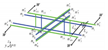
3.2 Relationship between External Force and Force Densities in ExpansionIf equal and opposite external force W is applied along y-axis on nodes n1, n2, n3, and n4 of two parallel bars b1 and b2 lying on xoy plane (Fig. 5), it will expand the structure and relocate all nodes and members from n to n', for all nodes and members are interconnected with each other. An external force that acts along the outward direction expanded the structure and increased the distance Ld by δd to a new distance Ld', and equal expansion was assumed along all axes. The new coordinates of the structure in expansion were the same as those in Eq.(1), except that the distance between two parallel bars Ld' was different. The inner bars illustrate when there is no external force acting on the structure, and outer bars represent the structure in expansion under the effect of external force W.
|
Fig.5 External force expanding the structure |
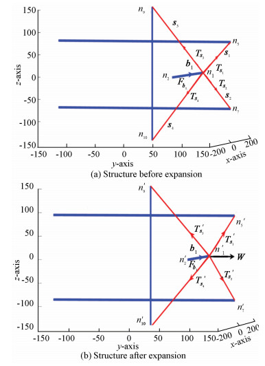
Fig. 6(a) shows the structure in a static position when there is no external force, and Fig. 6(b) shows the changes in the structure under the application of external force W that expands the structure. To study the effect of this external force on the structure in an outward direction, node 1 (n1) was analyzed in the calculation, and all forces acting on node are
|
Fig.6 External force expanding the structure |
| $ \mathit{\boldsymbol{W}} + {\mathit{\boldsymbol{F}}_{{\mathit{\boldsymbol{b}}_1}}} + \mathit{\boldsymbol{T}}_{{\mathit{\boldsymbol{s}}_1}}^\prime + \mathit{\boldsymbol{T}}_{{\mathit{\boldsymbol{s}}_2}}^\prime + \mathit{\boldsymbol{T}}_{{\mathit{\boldsymbol{s}}_3}}^\prime + \mathit{\boldsymbol{T}}_{{\mathit{\boldsymbol{s}}_4}}^\prime = 0 $ |
where W is the external force applied on node n1, which changes the internal force of all members. Fb1 is the force applied by bar b1, and T's1, T's2, T's3, and T's4 are the forces applied by strings s1, s2, s3 and s4 in an expanded structure (Fig. 6(b)).Therefore,
| $ \begin{array}{l} \mathit{\boldsymbol{W}} + {\lambda ^\prime }(n_1^\prime - n_2^\prime ) + \gamma _1^\prime (n_5^\prime - n_1^\prime ) + \gamma _2^\prime (n_7^\prime - n_1^\prime ) + \\ {\kern 1pt} {\kern 1pt} {\kern 1pt} {\kern 1pt} {\kern 1pt} {\kern 1pt} {\kern 1pt} {\kern 1pt} {\kern 1pt} {\kern 1pt} {\kern 1pt} {\kern 1pt} {\kern 1pt} {\kern 1pt} {\kern 1pt} {\kern 1pt} {\kern 1pt} {\kern 1pt} {\kern 1pt} {\kern 1pt} {\kern 1pt} {\kern 1pt} {\kern 1pt} {\kern 1pt} {\kern 1pt} \gamma _3^\prime (n_9^\prime - n_1^\prime ) + \gamma _4^\prime (n_{10}^\prime - n_1^\prime ) = 0 \end{array} $ |
Here note that equal expansion has been assumed, so force density γ' in all strings is the same for our analysis and bar force density can be expressed by λ' as
| $ \begin{array}{l} \mathit{\boldsymbol{W}} + {\lambda ^\prime }(n_1^\prime - n_2^\prime ) + {\gamma ^\prime }(n_5^\prime + n_7^\prime + n_9^\prime + n_{10}^\prime - \\ {\kern 1pt} {\kern 1pt} {\kern 1pt} {\kern 1pt} {\kern 1pt} {\kern 1pt} {\kern 1pt} {\kern 1pt} {\kern 1pt} {\kern 1pt} {\kern 1pt} {\kern 1pt} {\kern 1pt} {\kern 1pt} {\kern 1pt} {\kern 1pt} {\kern 1pt} {\kern 1pt} {\kern 1pt} {\kern 1pt} {\kern 1pt} {\kern 1pt} {\kern 1pt} {\kern 1pt} 4n_1^\prime ) = 0 \end{array} $ |
This equation in matrix form that defines three axes of coordinates can be written as
| $ \left[ {\begin{array}{*{20}{l}} 0\\ w\\ 0 \end{array}} \right] + {\lambda ^\prime }\left[ {\begin{array}{*{20}{l}} {n_{1x}^\prime - n_{2x}^\prime }\\ {n_{1y}^\prime - n_{2y}^\prime }\\ {n_{1z}^\prime - n_{2z}^\prime } \end{array}} \right] + {\gamma ^\prime }\left[ {\begin{array}{*{20}{l}} {n_{5x}^\prime + n_{7x}^\prime + n_{9x}^\prime + n_{10x}^\prime - 4n_{1x}^\prime }\\ {n_{5y}^\prime + n_{7y}^\prime + n_{9y}^\prime + n_{10y}^\prime - 4n_{1y}^\prime }\\ {n_{5z}^\prime + n_{7z}^\prime + n_{9z}^\prime + n_{10z}^\prime - 4n_{1z}^\prime } \end{array}} \right] = 0 $ |
Put all the values of the coordinates of nodes into
| $ \begin{array}{l} \left[ {\begin{array}{*{20}{c}} 0\\ w\\ 0 \end{array}} \right] + {\lambda ^\prime }\left[ {\begin{array}{*{20}{c}} {0.5{L_b} - ( - 0.5{L_b})}\\ {0.5L_d^\prime - 0.5L_d^\prime }\\ {0 - 0} \end{array}} \right] + \\ {\kern 1pt} {\kern 1pt} {\kern 1pt} {\kern 1pt} {\kern 1pt} {\kern 1pt} {\kern 1pt} {\kern 1pt} {\kern 1pt} {\kern 1pt} {\kern 1pt} {\kern 1pt} {\kern 1pt} {\gamma ^\prime }\left[ {\begin{array}{*{20}{c}} {0 + 0 + 0.5L_d^\prime + 0.5L_d^\prime - 4 \times 0.5{L_b}}\\ {0.5{L_b} + 0.5{L_b} + 0 + 0 - 4 \times 0.5L_d^\prime }\\ {0.5L_d^\prime + ( - 0.5L_d^\prime ) + 0.5{L_b} + ( - 0.5{L_b}) - 4 \times 0} \end{array}} \right] = 0 \end{array} $ |
So forces along the x-axis are
| $ \begin{array}{l} 0 + {\lambda ^\prime }(0.5{L_b} - ( - 0.5{L_b})) + {\gamma ^\prime }(0 + 0 + \\ {\kern 1pt} {\kern 1pt} {\kern 1pt} {\kern 1pt} {\kern 1pt} {\kern 1pt} (0.5L_d^\prime ) + (0.5L_d^\prime ) - 4 \times 0.5{L_b}) = 0 \end{array} $ |
| $ {\lambda ^\prime }({L_b}) + {\gamma ^\prime }(L_d^\prime - 2{L_b}) = 0 $ |
Forces along the y-axis are
| $ \begin{array}{l} \mathit{\boldsymbol{W}} + {\lambda ^\prime }(0.5L_d^\prime - 0.5L_d^\prime ) + {\gamma ^\prime }(0.5{L_b} + 0.5{L_b} + 0 + \\ {\kern 1pt} {\kern 1pt} {\kern 1pt} {\kern 1pt} {\kern 1pt} {\kern 1pt} {\kern 1pt} {\kern 1pt} {\kern 1pt} {\kern 1pt} {\kern 1pt} {\kern 1pt} {\kern 1pt} {\kern 1pt} {\kern 1pt} {\kern 1pt} {\kern 1pt} {\kern 1pt} {\kern 1pt} {\kern 1pt} {\kern 1pt} {\kern 1pt} {\kern 1pt} {\kern 1pt} {\kern 1pt} 0 - 4 \times (0.5L_d^\prime )) = 0 \end{array} $ |
| $ \mathit{\boldsymbol{W}} + {\lambda ^\prime }(0) + {\gamma ^\prime }({L_b} - 2L_d^\prime ) = 0 $ |
| $ \mathit{\boldsymbol{W}} = {\gamma ^\prime }(2L_d^\prime - {L_b}) $ |
| $ ∵\ {L_b} = 2L_d^\prime + 4\delta d $ |
| $ \therefore \mathit{\boldsymbol{W}} = {\gamma ^\prime }(2L_d^\prime - 2L_d^\prime - 4\delta d) $ |
Therefore,
| $ \mathit{\boldsymbol{W}} = - 4{\gamma ^\prime }\delta d $ | (4) |
There is no bar force along the y-axis, so Eq.(4) of external force is applied in terms of string force density.
Forces along z-axis are
| $ \begin{array}{l} {\lambda ^\prime }(0 - 0) + {\gamma ^\prime }((0.5L_d^\prime ) + ( - 0.5L_d^\prime ) + \\ {\kern 1pt} {\kern 1pt} {\kern 1pt} {\kern 1pt} {\kern 1pt} {\kern 1pt} {\kern 1pt} {\kern 1pt} {\kern 1pt} {\kern 1pt} {\kern 1pt} {\kern 1pt} {\kern 1pt} {\kern 1pt} {\kern 1pt} {\kern 1pt} {\kern 1pt} {\kern 1pt} {\kern 1pt} {\kern 1pt} {\kern 1pt} {\kern 1pt} 0.5{L_b} - 0.5{L_b} - 4 \times 0) = 0 \end{array} $ |
| $ {\gamma ^\prime }(0.5L_d^\prime - 0.5L_d^\prime + 0.5{L_b} - 0.5{L_b} - 4 \times 0) = 0 $ |
Since there is no effect of force along the z-axis direction, all forces are added to the x-axis and the y-axis directions as follows:
| $ {\lambda ^\prime }({L_b}) + {\gamma ^\prime }(L_d^\prime - 2{L_b}) + \mathit{\boldsymbol{W}} + {\gamma ^\prime }({L_b} - 2L_d^\prime ) = 0 $ |
| $ {\lambda ^\prime }({L_b}) - {\gamma ^\prime }({L_d} + {L_b}) + \mathit{\boldsymbol{W}} = 0 $ |
| $ ∵\ {L_b} = 2{L_d}^\prime + 4\delta d $ |
| $ \begin{array}{l} \therefore {\lambda ^\prime }(2L_d^\prime + 4\delta d) - {\gamma ^\prime }(L_d^\prime + 2L_d^\prime + 4\delta d) - \\ {\kern 1pt} {\kern 1pt} {\kern 1pt} {\kern 1pt} {\kern 1pt} {\kern 1pt} {\kern 1pt} {\kern 1pt} {\kern 1pt} {\kern 1pt} {\kern 1pt} {\kern 1pt} {\kern 1pt} {\kern 1pt} {\kern 1pt} {\kern 1pt} {\kern 1pt} {\kern 1pt} {\kern 1pt} {\kern 1pt} {\kern 1pt} {\kern 1pt} {\kern 1pt} {\kern 1pt} {\kern 1pt} {\kern 1pt} {\kern 1pt} {\kern 1pt} {\kern 1pt} {\kern 1pt} {\kern 1pt} {\kern 1pt} {\kern 1pt} {\kern 1pt} {\kern 1pt} {\kern 1pt} {\kern 1pt} {\kern 1pt} {\kern 1pt} {\kern 1pt} {\kern 1pt} {\kern 1pt} {\kern 1pt} {\kern 1pt} {\kern 1pt} {\kern 1pt} {\kern 1pt} {\kern 1pt} {\kern 1pt} {\kern 1pt} {\kern 1pt} {\kern 1pt} {\kern 1pt} {\kern 1pt} 4{\gamma ^\prime }\delta d = 0 \end{array} $ |
Thus the following equation is obtained:
| $ {\lambda ^\prime } = (\frac{{3L_d^\prime + 8\delta d}}{{2L_d^\prime + 4\delta d}}){\gamma ^\prime } $ | (5) |
It demonstrates the relation between string force density and bar force density in expansion.
4 Simulation ModelTwo individual models were established for analyzing the structure in compression and expansion processes, and the parameters are listed in Table 1.
| Table 1 Parameters of the simulation model |
4.1 Simulation for Compressing the Structure
A simulation work was performed in ADAMS for analyzing the motion of all bars and the elongation in all strings when same external force W acts on all four nodes of two parallel bars lying on one plane and compresses the structure (Fig. 3).
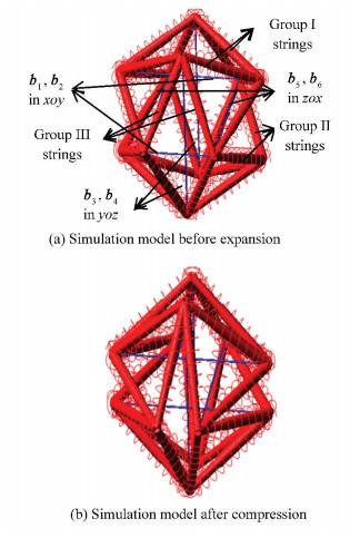
All strings have been replaced here by spiral springs and all bars have been displayed by solid lines (Fig. 7(a)). External force W was applied to act on bars b1 and b2 on xoy plane along y-axis direction, which squeezed the structure by relocating all nodes and decreased the distance between parallel bars b1 and b2 lying on xoy plane, b3 and b4 on yoz plane, and b5 and b6 on zox plane (Fig. 7(b)).
|
Fig.7 Simulation model for compression analysis |
4.1.1 Bars moment analysis
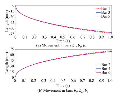
All bars in the structure moved inwards, squeezing the structure and decreasing the distance between two parallel bars. All parallel bars moved with the same distance in the opposite direction to each other and decreased the distance between Ld. When an external force W was applied on two parallel bars b1 and b2 along the y-axis, it was observed that different movement in bars lay on different planes while same and opposite movement in two parallel bars lay on the same plane. Parallel bars b1 and b2 lying on xoy plane experienced more movement and more decrease in the distance because of the direct effect of force, compared with those of parallel bars b3 and b4 on yoz and b5 and b6 on zox planes. Since parallel bars b3 and b4 received more indirect effect from the external force in compression, they experienced more movement and decrease in distance compared with parallel bars b5 and b6 (Fig. 8).
|
Fig.8 Movement analysis in all six bars in compression |
4.1.2 Elongation in string length
When an external force is applied on the structure in inward direction, it squeezes the whole structure and causes movement in all bars, resulting in the elongation of all strings in length. The 24 strings can be divided into three groups of 8 strings as per experiencing the same elongation in their length. All these 8 strings in each group which connect with bars that lie on two different planes had same elongation and deformation velocity (Fig. 9).

|
Fig.9 Elongation in length of strings in compression |
Fig. 2(b) and Fig. 7(a) show the details of all strings. Strings s1, s2, s5, s6, s9, s10, s13, s14, (categorized in Group Ⅰ) that connect with bars b1 and b2, and b3 and b4, had the same elongation in length and experienced deformation with same deformation velocity. Strings s3, s4, s7, s8, s11, s12, s15, s16 (categorized in Group Ⅱ)that connect with bars b5 and b6, and b1 and b2 had the same elongation in length and deformed with same deformation velocity. All other 8 strings s17, s18, s19, s20, s21, s22, s23, s24 (categorized in Group Ⅲ) connecting with bars b3 and b4 and b5 and b6 had the same elongation in length and received deformation with same deformation velocity.
The strings in Group Ⅰ experienced more elongation than all other strings, and those in Group Ⅲ had more elongation than those in Group Ⅱ in compressing the structure.
4.2 Simulation for Expanding the StructureA similar simulation work was performed in ADAMS for analyzing the motion of all bars and the elongation in all strings when same external force W acts on all four nodes of two parallel bars lying on one plane and expands the structure (Fig. 5).
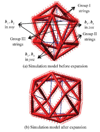
All strings have been replaced here by spiral springs and all bars have been displayed by solid lines (Fig. 10(a)). External force W was applied on bars b1 and b2 on xoy plane along the y-axis direction, which expanded the structure by relocating all nodes and increased the distance between parallel bars b1 and b2 lying on xoy plane, b3 and b4 on yoz plane, and b5 and b6 on zox plane (Fig. 10(b)).
|
Fig.10 Simulation model for expansion analysis |
4.2.1 Bars moment analysis
All bars in the structure moved outwards, expanding the structure and increasing the distance between two parallel bars, when an external force W was applied along one plane on the structure. All two parallel bars in one set of two bars moved with the same distance in the opposite direction to each other, leading to the increase in distance between these bars. When an external force was applied on two parallel bars b1 and b2 along the y-axis direction, it was found that different movement in bars lay on different planes whereas same and opposite movement in all two parallel bars lay on the same plane. Parallel bars b1 and b2 lying on xoy plane experienced more movement and more increase in distance, due to the direct effect of force compared with the other two sets of parallel bars (i.e., b3 and b4 lying on yoz plane and b5 and b6 on zox plane). Parallel bars b5 and b6 received more indirect effect of the external force in expansion, so they experienced more movement and increase in distance than parallel bars b3 and b4 (Fig. 11).
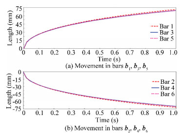
|
Fig.11 Movement analysis in all six bars in expansion |
4.2.2 Elongation in string
When an external force is applied to the structure in outward direction, it expands the whole structure and causes the movement in all bars, leading to the elongation of all strings in length. The 24 strings can be divided into three groups of 8 strings as per experiencing the same elongation in their length. All these 8 strings in each group which connect with bars lying on two different planes had same elongation and deformation velocity (Fig. 12).

|
Fig.12 Elongation in length of strings in expansion |
For details of all strings refer to Fig. 2(b) and Fig. 10(b). All 8 string s1, s2, s5, s6, s9, s10, s13, s14 (categorized in Group Ⅰ) that connect with bars b1 and b2 and b3 and b4 had the same elongation in length and deformed with the same deformation velocity. Strings s3, s4, s7, s8, s11, s12, s15, s16 (categorized in Group Ⅱ) that connect with bars b5 and b6 and b1 and b2 had same elongation in length and experienced deformation by same velocity. While all other 8 strings s17, s18, s19, s20, s21, s22, s23, s24 (categorized in Group Ⅲ) that connect with bars b3 and b4 and b5 and b6 had the same elongation in length and deformed with the same deformation velocity.
Strings in Group Ⅱ experienced more elongation than all others, and those in Group Ⅲ had more elongation than those in Group Ⅰ in the expansion of the structure.
4.3 Comparison of Structure in Compression and ExpansionIn this section, all the graphs mentioned above were zoomed in to compare with the results in compression and expansion processes of the structure regarding to dynamic symmetry.
4.3.1 Comparison in bars movementSince compression and expansion are opposite processes, the results obtained are also opposite as displayed in Table 2.
| Table 2 Movement in all bars in compression and expansion (mm) |
Two parallel bars b1 and b2 lying on the same plane had the same but opposite movement in compressing and expanding the structure (Table 2), which was the same for all other parallel bars that lay on the same plane. Furthermore, other two non-parallel bars b3 and b5 lying on different planes had the same movement but opposite in direction in compression and expansion. Same situation occurred for non-parallel bars b4 and b6 lying on different planes (Fig. 13).
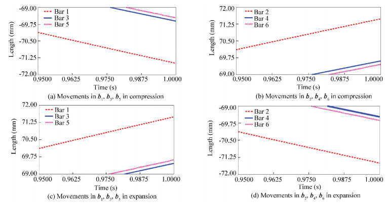
|
Fig.13 Movement analysis in all six bars in compression and expansion processes |
4.3.2 Comparison of elongation in strings
Since expansion is the inverse process of compression, when same external force was applied on a structure with same parameters in compression and expansion, noteworthy symmetrical and reversed results in the elongation of different strings were obtained. Strings (Group Ⅰ) that experienced maximum elongation in compression had a minimum elongation in the expansion of the structure, whereas strings (Group Ⅱ) that experienced minimum elongation in compression had a maximum elongation in the expansion, and those (Group Ⅲ) experienced medium elongation in compression had the same elongation in expansion (Table 3).
| Table 3 Elongation in strings during compression and expansion (mm) |
Strings s1, s2, s5, s6, s9, s10, s13, s14 (Group Ⅰ) in compression and strings s3, s4, s7, s8, s11, s12, s15, s16 (Group Ⅱ) in expansion had equal and maximum elongation. Strings (Group Ⅰ) in expansion and strings (Group Ⅱ) in compression had same and minimum elongation. Strings s17, s18, s19, s20, s21, s22, s23, s24 (Group Ⅲ) had same and medium elongation in compression and expansion (Fig. 14).
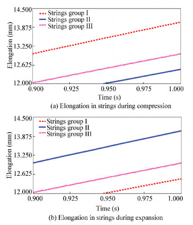
|
Fig.14 Elongation in strings |
5 Conclusions
In this paper, direct and indirect effects of external force on six bar tensegrity ball structure were studied in compression and expansion processes. The dynamic symmetry of the structure in both processes was analyzed, in which similar and reversed results were obtained. Unequal compression and expansion of the structure were observed when an external force was applied along one plane on two parallel bars by simulation. The parallel bars under direct effect of external force had maximum movement in compression and expansion compared with the other two sets which experienced indirect effect of force. Therefore, the assumption for the analytical calculations to develop the relationship between member force densities and the applied external force can be modified by the obtained correct simulation results. All strings can be divided into three groups as per the same dynamics, elongation, and deformation velocity.
| [1] |
Fuller R B. Tensile-integrity structures. U.S.: 3063521, 1959.
(  0) 0) |
| [2] |
Otto F. Tensile Structures. Cambridge: MIT Press, 1967: 52-96.
(  0) 0) |
| [3] |
Fuller R B, Applewhite E J. Synergetics: Explorations in the Geometry of Thinking. New York: Scribner, 1975.
(  0) 0) |
| [4] |
Sultan C. Chapter 2 tensegrity: 60 years of art, science, and engineering. Advances in Applied Mechanics, 2009, 43: 69-145. DOI:10.1016/S0065-2156(09)43002-3 (  0) 0) |
| [5] |
Skelton R E, de Oliveira M. Tensegrity Systems. Boston, MA: Springer, 2009.1-44. DOI: 10.1007/978-0-387-74242-7.
(  0) 0) |
| [6] |
Aldrich J B, Skelton R E. Backlash-free motion control of robotic manipulators driven by tensegrity motor networks. Proceedings of the 45th IEEE Conference on Decision and Control. Piscataway: IEEE, 2006.2300-2306. DOI: 10.1109/CDC.2006.377341.
(  0) 0) |
| [7] |
Chan W L, Skelton R E. Equilibria and stiffness of planar tensegrity structures. Proceedings of AAS/AIAA Space Flight Mechanics Meeting. Washington D.C.: AAS, 2002.
(  0) 0) |
| [8] |
Skelton R E, Adhikari R, Pinaud J P, et al. An introduction to the mechanics of tensegrity structures. Proceedings of the 40th IEEE Conference on Decision and Control. Piscataway: IEEE, 2001.4254-4259. DOI: 10.1109/CDC.2001.980861.
(  0) 0) |
| [9] |
Skelton R E, de Oliveira M C. Analysis of tensegrity dynamics. Tensegrity Systems. Boston, MA: Springer, 2009.157-178. DOI: 10.1007/978-0-387-74242-7_5.
(  0) 0) |
| [10] |
Luo A, Yang H, Liu H, et al. Compression process research of 6-bars tensegrity structure. Proceedings of 2017 IEEE International Conference on Mechatronics and Automation (ICMA). Piscataway: IEEE, 2017.1337-1341.
(  0) 0) |
| [11] |
Sultan C, Corless M, Skelton R E. Symmetrical reconfiguration of tensegrity structures. International Journal of Solids and Structures, 2002, 39(8): 2215-2234. DOI:10.1016/S0020-7683(02)00100-2 (  0) 0) |
| [12] |
Tibert G. Deployable tensegrity structures for space applications. Stockholm, Sweden: Royal Institute of Technology, 2002. DOI: 10.1177/026635119200700207.
(  0) 0) |
| [13] |
Furuya H. Concept of deployable tensegrity structures in space application. International Journal of Space Structures, 1992, 7(2): 143-151. (  0) 0) |
| [14] |
SunSpiral V, Gorospe G, Bruce J, et al. Tensegrity based probes for planetary exploration: entry, descent, and landing (EDL) and surface mobility analysis. International Journal of Planetary Probes, 2013, 7: 13. (  0) 0) |
| [15] |
Iscen A, Agogino A, SunSpiral V, et al. Controlling tensegrity robots through evolution. Proceedings of the 15th Annual Conference on Genetic and Evolutionary Computation. New York: ACM, 2013.1293-1300. DOI: 10.1145/2463372.2463525.
(  0) 0) |
| [16] |
Vespignani M, Friesen J M, SunSpiral V, et al. Design of SUPERball v2, a compliant tensegrity robot for absorbing large impacts (IROS). Proceedings of 2018 IEEE/RSJ International Conference on Intelligent Robots and Systems. Piscataway: IEEE, 2018.2865-2871.
(  0) 0) |
| [17] |
Zhang A, Cera B, Agogino A. Characterization of six-bar spherical tensegrity lattice topologies. Proceedings of IASS Annual Symposia. Madrin, Spain: International Association for Shell and Spatial Structures(IASS), 2018.1-7.
(  0) 0) |
| [18] |
Luo A, Skelton R E, Liu H, et al. Structure of the ball tensegrity robot. Proceedings of 2014 IEEE International Conference on Robotics and Biomimetics. Piscataway: IEEE, 2014.1781-1786. DOI: 10.1109/ROBIO.2014.7090593.
(  0) 0) |
 2021, Vol. 28


