In the development of modern wireless communication technology, microwave components with high frequencies always play pivotal roles. The film bulk acoustic resonator (FBAR) has been a topic of interest in labs as well as in particular applications, for it provides high operation frequency, an ultra-high quality (Q) factor, a large coupling coefficient, low volume, reduced cost, and good power handling capability[1-3]. The solidly mounted resonator(SMR), as a type of FBAR, consists of quarter-wave thick layers of alternating low and high acoustic impedance materials, a configuration referred to as the Bragg reflector[4]. The sound waves can be reflected by the Bragg reflector at every interface to form the resonance. A large percentage of the acoustic energy is reflected back into the resonator. Compared with the FBAR using an air/crystal interface on both faces of the resonator to trap acoustic energy, the SMR provides little risk of mechanical damage in any of the standard processes used in dicing, assembly, and packing[5].
The efficiency of the Bragg reflector depends on the number and ratio of alternating layers[6]. The common choice of low acoustic impedance material is silicon dioxide (SiO2) in the field[7-8]. Materials with large density, such as tungsten (W), platinum (Pt), and molybdenum (Mo), are usually used as high acoustic impedance layers. Consequently, the problem of parasitic capacitance, which will depress the performance of the whole chip, may be caused by the metallic nature of the high acoustic impedance layers[9]. If a dielectric material such as aluminum nitride (AlN) was applied, it would require more alternating layers to achieve the same efficiency as W/SiO2 layers[10]. Therefore, the use of a dielectric material with large acoustic velocity and impedance as the high acoustic impedance layers for an all-dielectric reflector becomes an excellent method of improving the quality of the SMR.
Diamond has the highest elastic constant and sound propagation velocity[11]. However, the high cost, limited size, and difficulty in the growing of single-crystalline diamond (SCD), and the rough surface of polycrystalline diamond (PCD), have seriously limited the use of chemical vapor deposition (CVD) diamond as a high acoustic impedance material of a SMR. Therefore, we used tetrahedral amorphous carbon (ta-C) and nanocrystalline diamond (NCD) films to solve these problems. The ta-C films, which are actually a type of hydrogen-free diamondlike carbon with more than 50% sp3 content, can be deposited at room temperature and appear as a smooth surface over a large area (12-inch diameter disk)[12-14]. The NCD film can also be deposited at a temperature lower than 500 ℃[15], and due to an average grain size of less than 100 nm, it has a smooth surface. Therefore, these two types of film are suitable for this application.
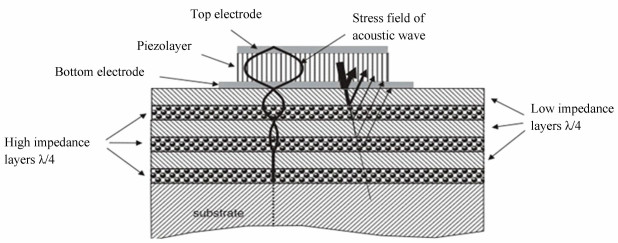
In this paper, the simulation analysis, which is independent from experiments confirming the reliability of NCD, realized the design of the SMR with high frequency and laid the foundations for experimental operation. The influence of Bragg reflectors on the properties of SMRs has been simulated using Mathcad based on the model of SMR shown in Fig. 1; the high acoustic impedance materials are W, ta-C, and NCD. Furthermore, we used an ADS (Advanced Design System) created by Agilent to simulate the model of SMR and investigate the influence of parasitic factors. By comparing the Q factor and impedance-frequency curve of ta-C, NCD, and traditional W metal, we concluded that NCD has better properties.
|
Fig.1 High acoustic impedance material structure |
1 Theoretical Considerations 1.1 Model of Resonator
According to Fig. 1, the piezoelectric stack is characterized by a three-layered configuration of Mo/AlN/Mo. The Bragg reflector consists of several pairs of alternating high and low acoustic impedance layers, under which is Si substrate. To maximize the energy that is reflected back to the resonator, the thicknesses of the high/low acoustic impedance layers should be equal to a quarter-wavelength of the resonant frequency.
To simulate the properties of the SMR, the input impedance as a function of frequency should be ascertained. Using mechanical and electrical theory and considering the boundary conditions, we derived the equations to describe the input impedance as shown below[16]:
| $ Z=\frac{1}{\mathrm{j} \omega C_{0}}\left[1-K^{2} \frac{\tan \left(k_{z} h\right)}{k_{z} h} \times\right. \\ \left.\frac{\left(Z'_{\text {top }}+Z'_{\text {bot }}\right) \cos ^{2}\left(k_{z} h\right)+{\rm{jsin}} \left(2 k_{z} h\right)}{\left(Z'_{\text {top }}+Z'_{\text {bot }}\right) \cos \left(2 k_{z} h\right)+{\rm{jsin}} \left(2 k_{z} h\right)\left(1+Z'_{\text {top }} Z'_{\text {bot }}\right)}\right] $ | (1) |
| $ Z'_{\mathrm{top}}=\frac{Z_{\mathrm{top}}}{Z_{p}^{c}}, Z'_{\mathrm{bot}}=\frac{Z_{\mathrm{bot}}}{Z_{p}^{c}}, Z_{p}^{c}=\sqrt{\rho c_{33}^{E}} $ | (2) |
wherein ρ and c33E are the density and the elastic constant respectively, C0 is the static capacitance, K2 is the electromechanical coupling factor, kz is the wave number (kz=2π/λ), ω is the angular frequency (ω=2πf), h is half the thickness of the piezoelectric film, Zpc is the acoustic impedance of the piezoelectric film, and Ztop' and Zbot' are the normalized acoustic impedance looking from the top to the upside and from the bottom to the downside of the piezoelectric film, respectively.
The load acoustic impedance above or below the piezoelectric film can be found using the transmission line equation [16]
| $ Z_{\mathrm{in}}=\left(Z_{\mathrm{mech}}\right) \frac{Z_{\text {load }}+\mathrm{j} Z_{\mathrm{mech}} \tan \left(k_{z} z\right)}{Z_{\mathrm{mech}}+\mathrm{j} Z_{\mathrm{load}} \tan \left(k_{z} z\right)} $ | (3) |
wherein Zmech represents the characteristic impedance of a mechanical transmission line section, Zload represents the input impedance of any point of the section, and z represents the distance between the point that Zload refers to and the position of Zin. We can obtain Ztop and Zbot as functions of frequency by substituting the characteristic impedance and thickness of the high/low acoustic impedance layers as well as electrodes. The boundaries of Ztop and Zbot are respectively 0 (the characteristic impedance of air) and the characteristic impedance of Si.
To complete the mathematical model thoroughly, the mechanical loss must be considered, so we can use complex propagation constant k' to replace the wave number kz[17]:
| $ k^{\prime}=k_{z} \cdot \sqrt{\frac{1}{1+\frac{\mathrm{j} \omega \eta_{33}^{E}}{c_{33}^{E}+e_{z 3}^{2} / \varepsilon_{z z}^{s}}}} $ | (4) |
wherein c33E, ez3, εszz, and η33E are the elastic constant, piezoelectric constant, dielectric constant, and coefficient of viscosity, respectively.
There are two important parameters of the SMR: the quality factor (Q) and the effective electro mechanical coupling factor (keff), which are defined as follows[18-19]:
| $ Q_{s / p}=\frac{f}{2}\left|\frac{\mathrm{d} \angle Z}{\mathrm{~d} f}\right|_{f_{s}} $ | (5) |
| $ k_{\mathrm{eff}}=\sqrt{\frac{f_{p}^{2}-f_{s}^{2}}{f_{p}^{2}}} $ | (6) |
where, ∠Z is the phase of the input impedance, and fs and fp are the series resonant frequency and parallel resonant frequency respectively. The Q factor denotes the energy loss of the SMR while keff denotes the bandwidth. Generally, the performance of the FBAR will be better when keff and Q are larger.
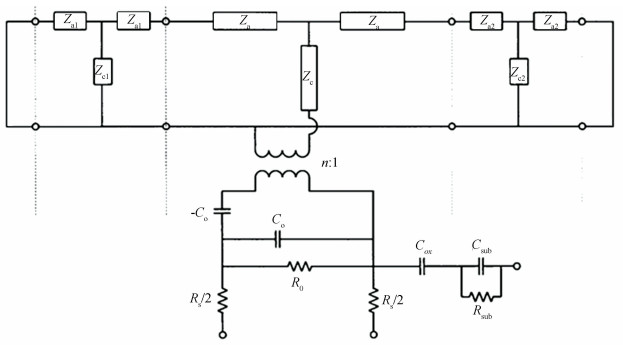
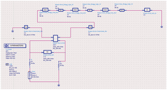
1.2 Simulation of ADSThe Advanced Design System (ADS) is a powerful electric-magnetic design and simulation software program by Agilent. We used it to simulate the parasitic influences of the FBAR, which are hard to calculate by math. The theoretical model discussed before can be abstracted as a Mason model [20], and Fig. 2 shows the equivalent circuit of the SMR. In this circuit, the upper part of the voltage transformer represents the mechanical circuit and the lower part represents the electrical circuit, so that the Mason model can simulate the transformation of mechanical and electrical energy in an electric circuit. The advantage and necessity of using ADS is that we can add parasitic factors easily. For example, if we want to know the influence of the parasitic capacitance between the bottom electrode and the W of the Bragg reflector, we just need to put a capacitance with the parameters of these materials in parallel like Cox. The simulation diagrams are shown in Fig. 3 and Fig. 4.
|
Fig.2 Simulation circuit of SMR |

|
Fig.3 Simulation diagram of SMR by ADS using W as a high acoustic impedance layer |
|
Fig.4 Simulation diagram of SMR by ADS using NCD as a high acoustic impedance layer |
2 Results and Discussion 2.1 Input Impedance by Mathcad
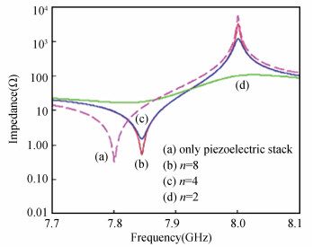
Fig. 5 shows the resonant curves of the designed SMR, wherein the parameter n denotes the number of alternating layers in the Bragg reflector. The broken curve represents the case with only the piezoelectric stack, which means that the film bulk acoustic resonator (FBAR) is in an ideal state in which the piezoelectric stack is working without the electrode or Bragg reflector. The parallel resonant response peak and series resonant response dip have no excursion but become sharper with increasing n, which illustrates that the reflection effect of the sound wave is ascribed to the number of alternating layers in the Bragg reflector. The efficiency improves as n increases, which means less energy loss and a higher Q factor.
|
Fig.5 SMR impedance curves for alternating layers of 2, 4, and 8 layers respectively and for piezoelectric stacks |
Compared with the case with only piezoelectric stacks, the parallel resonant frequency always agrees, but the series resonant frequency has an excursion to the right even with a larger n. This is because we designed the thicknesses of high/low acoustic impedance layers equal to a quarter-wavelength of the parallel resonant frequency, which is certainly smaller than a quarter-wavelength of the series resonant frequency. As λ=ν/f, a smaller λ ultimately leads to a larger f.
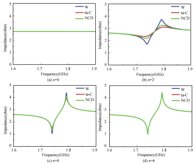
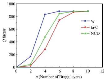
The resonant curves of W, ta-C, and NCD as the high acoustic impedance of the SMR are also compared in Fig. 6. The effects of the value of n are also plotted as functions of frequency. It shows that the parallel resonant response peak and series resonant response dip with W have a higher range and a sharper slope than the others with the same n, and that as n increases, the superiority of W gradually disappears and all three curves become nearly the same when n equals 6. We also compared the Q factor of each type of SMR for different n (Fig. 7). As we can see, the Q factor of the SMR with W as the high acoustic impedance layers is larger than the one with ta-C or NCD with the same n, when n is less than 10. This is ascribed to the larger characteristic acoustic impedance of W, which results in a larger impedance ratio and a better reflection efficiency. The Q factors of the SMR with different high acoustic impedance layers finally approach the same value when the value of n is equal to or greater than 10. Considering the cost of the technique, W is obviously the better option because it allows us to save layers. This means if we overlook the parasitic influences introduced by the metal, W as a high acoustic impedance material with good processing compatibility is a favorable choice. However, the parasitic factors can badly decrease the Q factor of the FBAR at high frequency, which will be discussed next.
|
Fig.6 Resonance curves of W, ta-C, and NCD as high acoustic impedance layers of SMR |
|
Fig.7 Q factor of W, ta-C, and NCD as the high acoustic impedance layer of SMR in different n |
2.2 Parasitic Influences and Q Factor
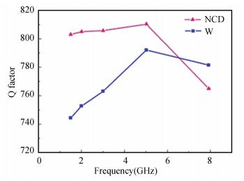
We used ADS to simulate the effect of W and NCD as high acoustic impedance layers on device quality factor. The reason why ta-C is not chosen as a high acoustic impedance layer is that, in the previous simulation, as shown in Fig. 6, the energy reflected by ta-C at the same layer number n is lower than that of W and NCD, and this material has the weakest reflection effect on acoustic wave. We also compared the Q factors when the resonance frequency ranges from 1.5 GHz to 8 GHz by reducing the thickness of the piezoelectric layer and electrodes. According to 2d=λ=ν/f, a small d (thickness of acoustic layer) leads to a large f. The result is shown in Fig. 8. When the frequency is lower than 6 GHz, NCD is evidently superior to W. This is because the parasitic influences of metal decrease the performance of the SMR.
|
Fig.8 Q factor of W and NCD as the high acoustic impedance layer of SMR at different resonant frequencies |
In this process, the resonant frequency increases higher than 3 GHz, Qs (Q factor in series resonant frequency) becomes very small. This is because the capacitive impedance of the parasitic capacitance between two electrodes becomes so small at high frequency that the impedance away from the resonant points becomes very small (Fig. 7). Therefore, the series resonant point, of which the impedance equals to zero, is not very sharp, and Qs becomes very small. We solved this in simulation by reducing the area of the "sandwich structure" to reduce the parasitic capacitance. The reducing ratio should allow the following formula:
| $ A=\alpha \frac{d}{f} $ | (7) |
where α is the ratio constant, and A is the area.
When the frequency is higher than 8 GHz, the area of the "sandwich structure" will become very small, nearly 0.14 mm2. The limited size will reduce the volume of power and cause difficulty in producing. Therefore, the FBAR cannot work at very high frequency, and in the range within which the FBAR can work, NCD is the best choice of high acoustic impedance material amongst metals and other dielectric materials.
3 ConclusionsBased on the theoretical model of a SMR, the input impedance and Q factor of SMR with W, ta-C, and NCD as high acoustic impedance layers were simulated by Mathcad. It has been shown that a Bragg reflector can improve the performance of a FBAR effectively, and 6 layers is the best choice when using W or NCD as the high acoustic impedance layer. The higher the impedance, the better. Next, the SMR with parasitic influence was simulated by ADS, and it was found that the parasitic factors can decrease the Q factor of SMR. Although many metals have a high acoustic impedance, they will cause parasitic effects which negatively affect the performance of the FBAR. Because the work frequency was limited by size, we only discuss the frequency range lower than 8 GHz. NCD with high acoustic impedance and electric resistance, and low mechanical loss, is therefore well suited to a Bragg reflector.
| [1] |
Fattinger G G. BAW Resonator design considerations - An overview. Proceedings of the 2008 IEEE International Frequency Control Symposium. Piscataway: IEEE, 2008.762-767. DOI: 10.1109/FREQ.2008.4623102.
(  0) 0) |
| [2] |
Xu W C, Choi S, Chae J. A contour-mode film bulk acoustic resonator of high quality factor in a liquid environment for biosensing applications. Applied Physics Letters, 2010, 96(5): 053703. DOI:10.1063/1.3309586 (  0) 0) |
| [3] |
Nirschl M, Schreiter M, Vörösb J. Comparison of FBAR and QCM-D sensitivity dependence on adlayer thickness and viscosity. Sensors & Actuators A: Physical, 2011, 165(2): 415-421. DOI:10.1016/j.sna.2010.11.003 (  0) 0) |
| [4] |
Chen D, Xu Y, Wang J J, et al. The AlN based solidly mounted resonators consisted of the all-metal conductive acoustic Bragg reflectors. Vacuum, 2010, 85(2): 302-306. DOI:10.1016/j.vacuum.2010.07.001 (  0) 0) |
| [5] |
Ruby R. Review and comparison of bulk acoustic wave FBAR, SMR technology. 2007 IEEE Ultrasonics Symposium Proceedings. Piscataway: IEEE, 2007.1029-1040. DOI: 10.1109/ULTSYM.2007.262.
(  0) 0) |
| [6] |
Jacobsen S M. Piezoelectric resonator with an efficient all-dielectric Bragg reflector. U.S. : US007463118B2.2008-12-09.
(  0) 0) |
| [7] |
Mai L, Song H, Tuan L M, et al. A comprehensive investigation of thermal treatment effects on resonance characteristics in FBAR devices. Microwave & Optical Technology Letters, 2005, 47(5): 459-462. DOI:10.1002/mop.21199 (  0) 0) |
| [8] |
Hassine N B, Mercier D, Renaux P, et al. Self heating under RF power in BAW SMR and its predictive 1D thermal model. Proceedings of the 2009 IEEE International Frequency Control Symposium Joint with the 22nd European Frequency and Time Forum. Piscataway: IEEE, 2009.237-240. DOI: 10.1109/FREQ.2009.5168176.
(  0) 0) |
| [9] |
Mai L, Lee J, Pham V-S, et al. A novel fabrication technique of FBAR devices for mobile broadband WiMAX applications. Microwave & Optical Technology Letters, 2008, 50(2): 375-378. DOI:10.1002/mop.23088 (  0) 0) |
| [10] |
Milyutin E, Gentil S, Muralt P. Shear mode bulk acoustic wave resonator based on c-axis oriented AlN thin film. Journal of Applied Physics, 2008, 104(8): 084508. DOI:10.1063/1.2996319 (  0) 0) |
| [11] |
Zhu J Q, Wang S, Jiang C Z, et al. Tetrahedral amorphous carbon films as a frequency-increasing interlayer of surface acoustic wave devices with a ZnO/Si configuration. Applied Physics A: Materials Science & Processing, 2009, 97(1): 195-200. DOI:10.1007/s00339-009-5160-z (  0) 0) |
| [12] |
He Y, Peng L, Robertson J. Fabrication and bio-functionalization of tetrahedral amorphous carbon thin films for bio sensor applications. Diamond & Related Materials, 2011, 20(7): 1020-1025. DOI:10.1016/j.diamond.2011.06.005 (  0) 0) |
| [13] |
Roch T, Lasagni A, Beyer E. Nanosecond UV laser graphitization and delamination of thin tetrahedral amorphous carbon films with different sp3/sp2 content. Thin Solid Films, 2011, 519(11): 3756-3761. DOI:10.1016/j.tsf.2011.01.338 (  0) 0) |
| [14] |
Zhu J Q, Han J C, Han X, et al. sp3-rich deposition conditions and growth mechanism of tetrahedral amorphous carbon films deposited using filtered arc. Journal of Applied Physics, 2008, 104(1): 13512-13520. DOI:10.1063/1.2951588 (  0) 0) |
| [15] |
Kromka A, Potocky Š, Čermák J, et al. Early stage of diamond growth at low temperature. Diamond and Related Materials, 2008, 17(7-10): 1252-1255. DOI:10.1016/j.diamond.2008.03.035 (  0) 0) |
| [16] |
Salgar S, Kim G, Han D-H, et al. Modeling and simulation of the thin film bulk acoustic resonator. Proceedings of the 2002 IEEE International Frequency Control Symposium and PDA Exhibition. Piscataway: IEEE, 2002.40-44. DOI: 10.1109/FREQ.2002.1075853.
(  0) 0) |
| [17] |
Lin R-C, Chen Y-C, Hsieh P-T, et al. Effects of substrate residue on the frequency response of high-tone bulk acoustic resonator. Proceedings of the 2007 IEEE International Frequency Control Symposium Joint with the 21st European Frequency and Time Forum. Piscataway: IEEE, 2007.695-698. DOI: 10.1109/FREQ.2007.4319164.
(  0) 0) |
| [18] |
Lakin K M, Kline G R, Mccarron K T. High Q microwave acoustic resonators and filters. IEEE Transactions on Microwave Theory and Techniques, 1993, 41(12): 2139-2146. DOI:10.1109/22.260698 (  0) 0) |
| [19] |
Nakamura K, Kanbara H. Theoretical analysis of a piezoelectric thin film resonator with acoustic quarter-wave multilayers. Proceedings of the 1998 IEEE International Frequency Control Symposium. Piscataway: IEEE, 1999.876-881. DOI: 10.1109/FREQ.1998.718003.
(  0) 0) |
| [20] |
Shim D S, Feld D A. A general nonlinear Mason model of arbitrary nonlinearities in a piezoelectric film. Proceedings of the 2010 IEEE International Ultrasonics Symposium. Piscataway: IEEE, 2010.295-300. DOI: 10.1109/ULTSYM.2010.5935834.
(  0) 0) |
 2021, Vol. 28


