2. National Key Laboratory of Science and Technology for National Defense on Advanced Composites in Special Environments, Harbin Institute of Technology, Harbin 150080, China;
3. School of Aeronautics and Astronautics, Harbin Institute of Technology, Harbin 150001, China;
4. Engineering College, Northeast Agricultural University, Harbin 150030, China
Ceramic matrix composites(CMC) exhibit excellent high temperature mechanical properties and thermo-physical properties, thus they are widely used in aerospace and aeronautical fields[1-2]. CMC and superalloy bolted joints are commonly used high temperature connection structures. As the weakest structural element, the design of bolted joint is of critical importance in improving load-bearing efficiency and maintaining structural integrity of the overall structure. The mechanical strength and failure behavior of bolted joint are generally influenced by numerous factors, such as fastener types, joint geometry, and assembly conditions. In previous design practices of bolted joint, the effects of assembly factors on mechanical performance were investigated by experimental and numerical methods for carbon-fiber/polymer composite bolted joint[3-10]. In the limited research on failure behaviors of CMC joint structures, Li et al.[9] studied the damage mode and fracture load of C/SiC joints via a comparison of the results of simulations and experiments. The influences of hole parameters including ratios of edge distance to diameter, width to diameter, and hole distance to diameter on the mechanical properties of C/SiC joints with pins or bolts were discussed. Zhao et al.[10] performed failure analyses of open-hole C/SiC composite laminates with different failure criteria and material degradation models by comparing the numerical results with existing experimental data. The failure process of a three-bolt C/SiC composite joint was predicted using the proposed progressive failure model. However, little attention was paid to the design of bolt based on tensile behavior of CMC bolted joints. In this work, a non-linear progressive damage model is firstly carried out to predict tensile performance and failure behavior of CMC/superalloy bolted joint with raised head bolt. The effects of bolt geometrical parameters on mechanical behaviors of the bolted joint are examined. The variations of failure load and associated damage mechanisms are discussed for the studied bolted joint.
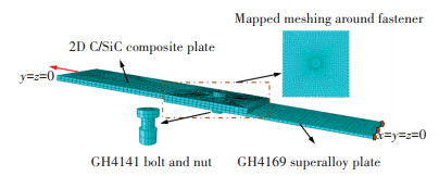
1 Finite Element ModelingA finite element model was established to simulate quasi-statically tensile loading of the C/SiC composite to GH4169 superalloy, single-bolt, single-lap joint via Abaqus/standard software, as illustrated in Fig. 1. Both the 2D woven C/SiC composite plate and superalloy plate were 120 mm long with 50 mm griping length. The thickness of the CMC plate and GH4169 alloy plate was 3.0 mm and 1.5 mm, respectively. The two plates were assembled together using a 5.0 mm diameter raised head bolt made of GH4141 alloy.
|
Fig.1 Finite element model of 2D C/SiC composite-superalloy bolted joint structure |
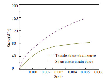
The 2D woven C/SiC composite was assumed as transversal isotropic material, and the constituent model exhibits non-linear behavior due to the progressive damage of matrix cracks, interface slipping and debonding, fiber failure, and fiber pull- out during tensile loading. To address the nonlinear stress-strain relationship of C/SiC composites, a macroscopic constituent model proposed by Li et al.[11] is adopted here to characterize the mechanical behavior of 2D plain-woven C/SiC composite materials. The experimental stress-strain curves under uniaxial tension and shear loads for the 2D plain-woven C/SiC composite material provided by the material suppliers are shown in Fig. 2. The rest of mechanical properties of the composite material used for analysis are summarized in Table 1. Due to higher yield strength of superalloy than that of CMC, the failure process of the bolted joint was dominated by the composite plate. Therefore, only elastic behavior of the superalloy plate and bolt was considered in this analysis, and the assigned mechanical properties of the superalloys are summarized in Table 2[12].
|
Fig.2 The measured stress-stain curves provided by material suppliers for a 2D plain-woven C/SiC composite plate under uniaxial tension and shear loading |
| Table 1 Mechanical properties of 2D plain-woven C/SiC composite material |
| Table 2 Mechanical properties of GH 4169 and GH4141 superalloy |
Three-dimensional eight-node reduced-integration C3D8R elements with hourglass control were used to discretize the composite laminates, superalloy plate, and mechanical fastener. Five contact pairs for the joint structure were defined between fastener shank and holes of plates, fastener head or nut and the outer surfaces of the two plates, and the faying surface of two plates. A finite sliding contact and surface to surface contact formulations were adopted between all contact interfaces in the model. A classic Coulomb friction was assigned to all contacted surfaces with friction coefficient of 0.3. Bolt-hole clearance of 0.8% and 6 kN preload were applied for the finite element model of all the considered joints in ABAQUS. The right end of superalloy plate was held fixed in all three translational directions (Ux, Uy and Uz). The left end of the composite plate was held fixed in two translational directions (Uy and Uz) and three rotational directions (Rx, Ry and Rz), while a prescribed displacement load was applied along Ux direction to mimic a quasi-static tensile loading.
2 Progressive Damage Analysis MethodA progressive failure analysis of C/SiC composite and superalloy bolted joint structure was implemented by using the commercial ABAQUS software. A user-defined subroutine UMAT including the nonlinear constitutive model, failure criterion, and material degradation rule was embedded into the finite element model. The proposed analysis method started with the generation of finite element model for the studied bolted joint by using the material properties, geometrical parameters, boundary conditions, initial load and load step as inputs. Then, a non-linear stress analysis was carried out to calculate stress at each element on the bolted joint using the above-described constituent models. For the current analysis, Tsai-Wu strength criterion[13] was adopted for evaluation of failure occurrence on the basis of the calculated structural stresses. If the failure criterion is violated, the applied load was increased by a load increment and the stiffness parameters for CMC were updated in accordance with the obtained stress levels. Otherwise, if the final structural failure was not satisfied, the material stiffness parameters were reduced to 1% of its undamaged value for the C/SiC composite. The simulation was terminated until encountering the final failure of the composite structure or severe convergence difficulties.
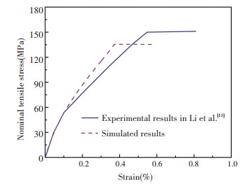
To validate the proposed damage analysis method for the 2D woven C/SiC composite materials, a tensile process of an open-hole laminate was simulated for lack of data on C/SiC composite and superalloy bolted joint in open publications. The geometric configuration, mechanical properties, and measured stress-stain curves of the 2D woven C/SiC composite for this validation were given in the literature[11]. The uniaxial tensile process for the open-hole composite plate was simulated by using the commercial FEA software ABAQUS, and the predicted tensile stress-strain relationship is shown in Fig. 3. The comparison of the simulated and experimental results[11] showed that the predicted strength of 135.5 MPa using the developed method was in good agreement with the experimental value of 150 MPa, with a relative error of 9.6%, which validated the effectiveness of the proposed progressive failure model in this paper. A relative error of no more than 10% is acceptable in engineering applications, considering that various factors can result in errors between the measured and predicted results, such as the scattering of experimental results caused by various levels of intrinsic defects in fabrication of composites, simplifications in finite element model, and the selected failure criterion and degradation rule in the progressive damage simulation.
|
Fig.3 Comparison of simulated tensile stress and strain relationship with experimental results in Li et al.[11] for 2D woven C/SiC composite open-hole plate |
3 Results and Discussions 3.1 Effect of Bolt Diameter
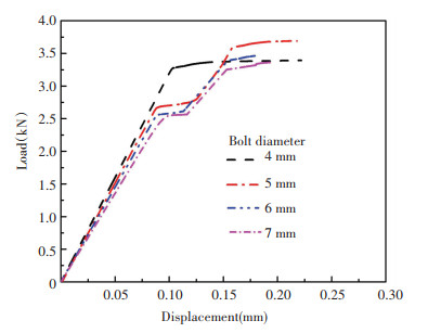
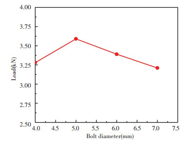
The uniaxial tensile performances of the CMC/superalloy bolted joint were simulated by using the established progressive damage analysis method. Given the bolt head diameter of 10 mm, and thickness of bolt head of 2.5 mm, the simulated load-displacement curves under various bolt diameters for the mechanically fastened joints are illustrated in Fig. 4. The declining slope of curves demonstrates that the initial stiffness of the bolted joint drops with the rise of bolt diameter. The failure load as function of bolt diameter for the bolted joints is shown in Fig. 5. As can be seen, the final failure load increases first to the maximum value of 3.59 kN as the bolt diameter is 5 mm, and then decreases with the rise of bolt diameter, indicating there is an optimum value of the bolt diameter in maximizing the load bearing capacity of the joint structure.
|
Fig.4 Load-displacement relationships for the C/SiC composite and superalloy bolted joint under various bolt diameters |
|
Fig.5 The failure load as function of bolt diameter for the bolted joints |
3.2 Effect of Bolt Head Diameter
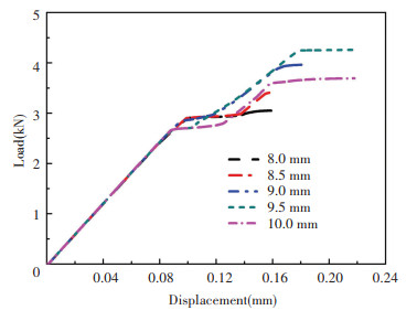
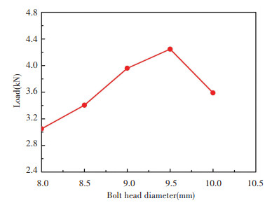
Given the bolt diameter of 5 mm, and bolt head thickness of 2.5 mm, the simulated load-displacement curves under different bolt head diameters in tensile loading of the joints are plotted in Fig. 6. As shown in the figure, the initial stiffness of the joints shows limited change with the variation of bolt head diameter for the considered conditions. However, the final failure load, as plotted in Fig. 7, grows dramatically from 3.05 kN to 4.25 kN as the bolt head diameter rises from 8.0 mm to 9.5 mm, and then decreases a certain amount when it increases to 10 mm. Compared with the joint with 8 mm bolt head diameter, the ultimate failure load improves about 39% for 1.5 mm increase in the bolt head diameter. The variation of the load bearing capacity can be attributed to the degree of stress concentration around the fastening area of CMC plate. When the stress concentration intensifies, the final failure load will decrease. Both the tensile and compressive stress concentration will have an adverse effect on the load bearing capacity of the structure. The simulated axial stress contour maps of the CMC plate for different bolt head diameters at 1.5 kN tensile load are depicted in Fig. 8. When the bolt head diameter is 9.5 mm, the stress concentration level around hole boundary of the CMC plate is relatively lower than the results for other design cases, and therefore the bearing capacity of the joint reaches the maximum value. The final failure areas around the fastener hole of the CMC plate are illustrated with the variation of bolt head diameter in Fig. 9. As demonstrated in the figures, the failure mode of all the considered joints is load bearing failure. The joints with larger bolt head diameter exhibit more extensive damage areas in comparison with the smaller diameter cases as the structures fail. The number of failure elements on the left side of CMC plate hole increases when the size of bolt head diameter increases, due to larger area on top of the CMC plate being covered by bolt head at the fastening area.
|
Fig.6 Load-displacement relationships for the C/SiC composite and superalloy bolted joint under different bolt head diameters |
|
Fig.7 The failure load as function of bolt head diameter for the bolted joints |

|
Fig.8 Axial stress contour maps of the composite plate for different bolt head diameters when the joint structures are applied 1.5 kN tensile load |

|
Fig.9 The final failure areas of the C/SiC composite plate under various bolt head diameters |
3.3 Effect of Thickness of Bolt Head
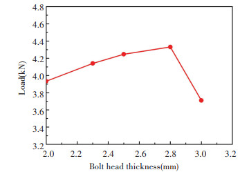
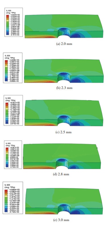
When the bolt diameter and bolt head diameter are 5.0 mm and 9.5 mm, the load-displacement curves under different bolt head thicknesses in tensile loading of the joints are plotted in Fig. 10. As discussed in the former cases, the initial stiffness of the joints is almost constant as the bolt head thickness varying from 2.0 mm to 3.0 mm. The failure load as function of bolt diameter for the bolted joints is shown in Fig. 11. The final failure load improves around 10% as the thickness of bolt head increases from 2.0 mm to 2.8 mm. 0.2 mm larger thickness of bolt head than 2.8 mm design results in about 14% drop in the final failure load. From the depicted axial stress contour maps of the CMC plate for different bolt head thicknesses at 1.5 kN tensile load in Fig. 12, the stress concentration level around hole boundary of the CMC plate decreases to the minimum value as the bolt head thickness is 2.8 mm, and therefore the bearing capacity of the joint reaches the maximum value.

|
Fig.10 Load-displacement relationships for the C/SiC composite and superalloy bolted joint under different bolt head thicknesses |
|
Fig.11 The failure load as function of bolt head thickness for the bolted joints |
|
Fig.12 Axial stress contour maps of the composite plate for different bolt head thicknesses when the joint structures are applied 1.5 kN tensile load |
4 Conclusions
A finite element model in combination with progressive damage analysis was established to predict tensile performance and associated failure behavior of 2D C/SiC composite and superalloy bolted joint with raised head bolt. The Tsai-Wu failure criterion was selected to evaluate the damage occurrence of CMC material. Progressive failure analysis for the bolted joint was implemented by using a user-defined subroutine UMAT embedded into the general package ABAQUS. The effects of bolt geometrical parameters on stress distribution, tensile performance, and damage process were studied for the CMC-superalloy bolted joint structures. The results showed that the final failure load increased first to the maximum value, and then decreased with the rise of the bolt diameter, bolt head diameter, and bolt head thickness, respectively. Among the three bolt parameters, the failure load of the joint was more sensitive with the variation of the bolt head diameter. When the bolt diameter, diameter and thickness of bolt head were 5.0 mm, 9.5 mm, and 2.8 mm for the joint congiguration, the joint structure gave the maximum load bearing capacity for the considered ranges of bolt parameters. It was also found that it is possible to realize around 42% improvement in load bearing capacity of the structure by small adjustments in the bolt parameters of bolted joints.
| [1] |
Naslain R. Design, preparation and properties of non-oxide CMCs for application in engines and nuclear reactors: an overview. Composites Science and Technology, 2004, 64(2): 155-170. DOI:10.1016/S0266-3538(03)00230-6 (  0) 0) |
| [2] |
Bohrk H, Beyermann U. Secure tightening of a CMC fastener for the heat shield of re-entry vehicles. Composite Structures, 2010, 92(1): 107-112. DOI:10.1016/j.compstruct.2009.07.002 (  0) 0) |
| [3] |
McCarthy C T, McCarthy M A. Three-dimensional finite element analysis of single-bolt, single-lap composite bolted joints: Part Ⅱ—effects of bolt-hole clearance. Composite Structures, 2005, 71(2): 159-175. DOI:10.1016/j.compstruct.2004.09.023 (  0) 0) |
| [4] |
McCarthy M A, McCarthy C T, Lawlor V P, et al. Three-dimensional finite element analysis of single-bolt, single-lap composite bolted joints: Part I—model development and validation. Composite Structures, 2005, 71(2): 140-158. DOI:10.1016/j.compstruct.2004.09.024 (  0) 0) |
| [5] |
Egan B, McCarthy C T, McCarthy M A, et al. Stress analysis of single-bolt, single-lap, countersunk composite joints with variable bolt-hole clearance. Composite Structures, 2012, 94(3): 1038-1051. DOI:10.1016/j.compstruct.2011.10.004 (  0) 0) |
| [6] |
Qin T L, Zhao L B, Zhang J Y. Fastener effects on mechanical behaviors of double-lap composite joints. Composite Structures, 2013, 100: 413-423. DOI:10.1016/j.compstruct.2013.01.008 (  0) 0) |
| [7] |
Chishti M, Wang C H, Thomson R S, et al. Numerical analysis of damage progression and strength of countersunk composite joints. Composite Structures, 2012, 94(2): 643-653. DOI:10.1016/j.compstruct.2011.08.030 (  0) 0) |
| [8] |
Chishti M, Wang C H, Thomson R S, et al. Experimental investigation of damage progression and strength of countersunk composite joints. Composite Structures, 2012, 94(3): 865-873. DOI:10.1016/j.compstruct.2011.10.011 (  0) 0) |
| [9] |
Li G D, Wu X F, Zhang C R, et al. Theoretical simulation and experimental verification of C/SiC joints with pins or bolts. Materials and Design, 2014, 53: 1071-1076. DOI:10.1016/j.matdes.2013.08.001 (  0) 0) |
| [10] |
Zhao L B, Yang W, Cao T C, et al. A progressive failure analysis of all-C/SiC composite multi-bolt joints. Composite Structures, 2018, 202: 1059-1068. DOI:10.1016/j.compstruct.2018.05.029 (  0) 0) |
| [11] |
Li J, Jiao G Q, Wang B, et al. A nonlinear damage constitutive model for 2D woven C/SiC composite material and its application. Acta Materiae Compositae Sinica, 2013, 30(1): 165-171. DOI:10.13801/j.cnki.fhclxb.2013.01.034 (  0) 0) |
| [12] |
Editorial Committee of China Aeronautical Materials Handbook. China Aeronautical Materials Handbook. Beijing: China Standards Press, 2002: 323-356.
(  0) 0) |
| [13] |
Tsai S W, Wu E M. A general theory of strength for anisotropic materials. Journal of Composite Materials, 1971, 5(1): 58-80. DOI:10.1177/002199837100500106 (  0) 0) |
 2021, Vol. 28


