Nowadays, the manufacturing industry is developing towards high precision, and the reliability of mechanism has attracted more attention. Because planar linkage mechanisms are composed of several rigid components connected by kinematic pair, there will be an unavoidable clearance between the kinematic pairs in actual working process. The clearance will inevitably affect dynamic responses of mechanism[1]. Thus, research of mechanism with clearance is of great significance. In addition, due to clearance, the mechanism will produce uncertain motion, which shows some non-linear characteristics, and chaotic phenomenon is very common in the non-linear characteristics. Chaotic motion is unpredictable and has a great negative impact on the mechanism. Thus, the study of non-linear characteristics is an important basis for the fatigue life prediction of mechanism.
Research work has made some progress at simple single DOF mechanisms with one clearance recently, while there are few studies on complex multi-DOF mechanisms with clearances. Chen et al.[2] researched effects of clearance and flexible members of dynamic characteristics about multi-link mechanism. Salahshoor et al.[3] studied different influence factors on crank-slider mechanism with clearances comprehensively. Wang and Wang[4] built an actual dynamical model of 4-SPS/PS mechanism by introducing rigid nodes, and carried out simulation research on the model. Wang et al.[5] proposed a way of connection of the rotary clearance of the planar system. Chen and Jiang[6] carried out nonlinear analysis and chaos identification of planar six-bar mechanism with clearance, which provided theoretical support for the selection of clearance. Tian et al.[7] carried out dynamic analysis and numerical calculation of mechanical system with clearances and incomplete connections and put forward an effective experimental way. Chen et al.[8] identified the chaos of 4-UPS-RPU mechanism through phase diagram and Poincaré mapping, then found that chaos appeared in mechanism under specific conditions. Erkaya[9] analyzed effects of spherical clearances connection and flexibility connection in mechanisms. Wang and Liu[10] analyzed three-dimensional wear of 4-DOF mechanisms and obtained the dynamical responses. Flores and Lankarani[11] proposed some method to study dynamical model of planar mechanism with clearances, then analyzed effects of one clearance and multi-clearances on planar systems. Ahmedalbashir et al.[12] researched dynamical response of planar mechanism by MATLAB. Tan et al.[13] analyzed a kind of crank block with revolute clearances, then studied influence of clearance value and friction coefficient in dynamic characteristics.
Nowadays, research of planar mechanism mostly focuses on dynamical responses of mechanism, while there is limited research on chaotic phenomenon, which mainly aims at the chaotic phenomenon of the end-effector of mechanism. But in this paper, not only the chaotic phenomenon is studied in greater depth, but also the chaotic phenomenon at the clearance joint is studied. Jiang and Chen[14] optimized design of multi-link mechanism, which reduced the negative influence caused by the wear, and carried out the nonlinear analysis on the mechanism. Xiang et al.[15] put forward a kind of mixed friction model to analyze dynamical responses of planar mechanism, compared various friction models, and studied influence of friction on manipulator. Chen et al.[16] discussed dynamical responses and non-linear characteristic of 4-UPS-UPU spherical mechanism, and verified correctness of the model by virtual prototype simulation. Tan et al.[17] established dynamical responses equation of mechanism and researched effects of friction in dynamical response with clearance. Ma and Qian[18] proposed a method of rigid body dynamical model of planar crank block with full rotating pair clearance, and used LuGre model to describe tangential friction at gap, then verified the accuracy of the model. Wei et al.[19] transformed steering mechanism into planar simple mechanisms, discussed effects of different parameters on stability of mechanism, and analyzed chaotic phenomena. Hou et al.[20] studied RU-RPR decoupled parallel mechanism, and analyzed the chaos at different driving speeds and friction coefficients. Li et al.[21] considered the normal contact force effect and tangential friction effect at clearance joint by using nonlinear contact force model and modified Coulomb friction model, then studied the effect and interaction of clearance connection, which provided a reliable basis for the selection of clearance size.
Based on the above review, previous studies mainly focused on simple mechanisms, and few on multi-degree-of-freedom complex mechanism with clearances. In addition, there is limited research on chaotic phenomena, which is mainly about the analysis of mechanism chaos, while research on clearance chaos is little. With the purpose of studying dynamic response and non-linear characteristics of multi-degree-of-freedom and multi-clearance complex mechanism, a dynamical model of multi-clearance 2-DOF mechanism was established and analyzed, then the dynamics response was given. In addition, the chaotic phenomena of clearance were studied by Poincaré mappings, bifurcation diagram, and phase diagram. Firstly, normal collision force and tangential friction force were modeled by Lankarani-Nikravesh model and Coulomb model separately. Then the dynamics equation of multi-clearance planar mechanism was established by Lagrange equation. Dynamical characteristics under different clearance numbers, different clearance values, and different positions were analyzed. Through Poincaré map and bifurcation diagram, the non-linear dynamic characteristics of mechanism under different clearance value and driving speed were discussed.
1 Establishment of Contact Force Model 1.1 Revolute Clearance Motion ModelWith the purpose of developing an ideal motion model of rotating clearance, a geometric description of bearings and shafts in motion pairs were made first. The motion model is illustrated in Fig. 1.

|
Fig.1 The clearance model |
As Fig. 1 shows, element i and element j are bearings and shafts. Local coordinates frames are xioiyi and xjojyj. Global coordinate frame is XOY.
According to the illustration in Fig. 1, eccentricity vector is
| $ \boldsymbol{e}_{i j}=\boldsymbol{r}_{j}^{P}-\boldsymbol{r}_{i}^{P} $ | (1) |
where Pi and riP represent the rotating center and position vector of fixed coordinate frame in bearing; Pj and rjP represent the rotating center and position vector of fixed coordinate frame in shaft.
Unit normal vector is written as
| $ \boldsymbol{n}_{i j}=\frac{\boldsymbol{e}_{i j}}{e_{i j}} $ | (2) |
where
When collision occurs, the position vector of collision points is expressed as
| $ \left\{\begin{array}{l} \boldsymbol{r}_{i}{ }^{Q}=\boldsymbol{r}_{i}{ }^{P}+R_{i} \boldsymbol{n}_{i j} \\ \boldsymbol{r}_{j}{ }^{Q}=\boldsymbol{r}_{j}{ }^{P}+R_{j} \boldsymbol{n}_{i j} \end{array}\right. $ | (3) |
where Qi and Qj denote the collision point of bearing and shaft.
The velocity of bearing and shaft at contact point can be given as
| $ \left\{\begin{array}{l} \dot{\boldsymbol{r}}_{i}{ }^{Q}=\dot{\boldsymbol{r}}_{i}{ }^{P}+R_{i} \dot{\boldsymbol{n}}_{i j} \\ \dot{\boldsymbol{r}}_{j}{ }^{Q}=\dot{\boldsymbol{r}}_{j}{ }^{P}+\boldsymbol{R}_{j} \dot{\boldsymbol{n}}_{i j} \end{array}\right. $ | (4) |
The relative normal and tangential velocities are expressed by
| $ \left\{\begin{array}{l} v_{n}^{i j}=\left(\dot{\boldsymbol{r}}_{j}{ }^{Q}-\dot{\boldsymbol{r}}_{i}{ }^{Q}\right)^{\mathrm{T}} \boldsymbol{n}_{i j} \\ v_{t}^{i j}=\left(\dot{\boldsymbol{r}}_{j}{ }^{Q}-\dot{\boldsymbol{r}}_{i}{ }^{Q}\right)^{\mathrm{T}} \boldsymbol{t}_{i j} \end{array}\right. $ | (5) |
When shaft and bearing collide, the depth of penetration could be given as
| $ \delta_{i j}=e_{i j}-c_{i j} $ | (6) |
where cij is clearance size whose value is Ri-Rj, Ri and Rj represent the radius of bearing and shaft, respectively.
Through the geometric relationship between the shaft and the bearing, the contact conditions of the collision can be obtained as follows:
| $ \left\{\begin{array}{l} \delta_{i j}=e_{i j}-c_{i j}<0 \\ \delta_{i j}=e_{i j}-c_{i j}=0 \\ \delta_{i j}=e_{i j}-c_{i j}>0 \end{array}\right. $ | (7) |
The condition of collision between bearing and shaft is
| $ \delta_{i j}\left(T_{n}\right) \delta_{i j}\left(T_{n+1}\right) \leqslant 0 $ |
When δij(Tn) < 0 and δij(Tn+1) < 0, shaft and the bearing do not collide;
When δij(Tn) < 0 and δij(Tn+1)>0, the shaft and the bearing change from free motion to collision;
When δij(Tn)>0 and δij(Tn+1)>0, the shaft and the bearing collide;
When δij(Tn)>0 and δij(Tn+1) < 0, the shaft and bearing change from collision to free motion;
When δij(Tn)δij(Tn+1)=0, shaft and the bearing contact with each other.
1.2 Normal Contact Force ModelBased on the elastic force and energy dissipation caused by impact, the normal collision contact force was achieved by modifying Hertz contact force model by Lankarani-Nikravesh. This model takes into account the energy loss and material properties in the collision process, and has the advantages of simple contact force model, convenient calculation, fast convergence speed, and simple numerical integration algorithm. It is widely used in multi-body system[22-23], which has been validated by experimental studies[24]. According to Ref. [25], the following equation is given:
| $ F_{n}=K \delta^{n}+D \dot{\delta}_{i j} $ | (8) |
where
D is modified damping coefficient, which is given as
| $ D=\frac{3 K\left(1-c_{e}{}^{2}\right) \delta_{i j}{}^{n}}{4 \dot{\delta}_{i j}^{(-)}} $ | (9) |
where ce stands for recovery coefficient,
To prevent numerical difficulty, the modified Coulomb model is normally used. This model can prevent direction mutation of tangential contact force, and has a clearance joints array system and a relatively simple model, which can improve the computational efficiency. Thus it is widely used in mechanism with clearances. According to Ref. [26], tangential friction is as below:
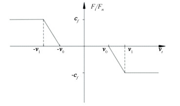
| $ \begin{aligned} F_{t}=-c_{f} c_{d}& F_{n} \frac{v_{t}}{\left|v_{t}\right|}= \\ &\left\{\begin{array}{ll} 0, & \left|v_{t}\right|<v_{0} \\ -c_{f} \frac{\left|v_{t}\right|-v_{0}}{v_{1}-v_{0}} F_{n} \frac{v_{t}}{\left|v_{t}\right|}, & v_{0} \leqslant\left|v_{t}\right| \leqslant v_{1} \\ -c_{f} F_{n} \frac{v_{t}}{\left|v_{t}\right|}, & \left|v_{t}\right|>v_{1} \end{array}\right. \end{aligned} $ | (10) |
where cf is friction coefficient, cd represents dynamic correction coefficient, v0 and v1 represent extreme static and dynamic friction velocities, respectively.
When tangential velocity approaches zero, dynamic correction coefficient can effectively prevent the sudden change of friction direction. Fig. 2 shows the change trend of Ft/Fn with vt, which is truly helpful for the solution of the formula.
|
Fig.2 The diagram of Ft/Fn over Vt |
According to Ref. [27], equivalent force and moment are expressed by
| $ \left\{\begin{array}{l} f_{i j}^{y}=F_{n} n+F_{t} t=\left[f_{i j}{ }^{x} \quad f_{i j}{ }^{y}\right]^{\mathrm{T}} \\ \operatorname{mom}_{i j}=-\left(y_{i}^{Q_{i}}-y_{i}\right) f_{i j}{ }^{x}+\left(x_{i}^{Q_{i}}-x_{i}\right) f_{i j}{ }^{y} \\ \operatorname{mom}_{j i}=-\left(y_{j}^{Q_{j}}-y_{j}\right) f_{j i}{ }^{x}+\left(x_{j}^{Q_{j}}-x_{j}\right) f_{j i}{ }^{y} \end{array}\right. $ | (11) |
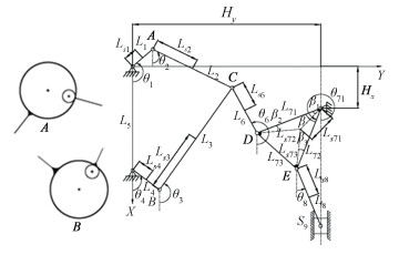
As shown in Fig. 3, planar mechanism(each rod is a homogeneous rod) consisted of frames, crank 1, connecting rod 2, connecting rod 3, crank 4, connecting rod 6, triangular plate 7, connecting rod 8, and slider 9. Crank 1, crank 4, and triangle plate 7 were connected to different racks by hinge. Connecting rod 3 connects with connecting rod 2, crank 4, and connecting rod 6 respectively by revolute pair, while another end of connecting rod 2 was connected with crank 1. Triangle plate 7 was connected with connecting rod 6 and connecting rod 8 respectively by rotating pair, and the other end of connecting rod 8 was connected with slider 9 through revolute pair. Slider 9 was located in the fixed guide rail. The DOF of planar mechanism was 2. The motor drove the movement of crank 1 and crank 4 to realize the power input of the whole mechanism. Crank 1 and connecting rod 2, crank 4 and connecting rod 3 were connected by the revolute joint A and revolute joint B, respectively. Since crank 1 and 4 were the direct drive parts of motor, the influences of clearance on dynamical response can be better analyzed at revolute joints A and B.
|
Fig.3 Structure diagram of mechanism |
2.2 Dynamic Modeling Process
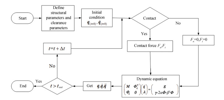
Fig. 4 is the flow chart of dynamic solution:
|
Fig.4 Flow chart of dynamic solution |
1) Firstly, matrices and vector were described by MATLAB. The initial conditions, structural parameters (geometric parameter), and clearance parameters of mechanism were defined;
2) Mathematical model was built. Kinematic analysis of each clearance joint was carried out to judge whether the shaft and bearing collided;
3) If the penetration depth δij≥0, the contact impact mode occurred. The normal contact force (Fn) was calculated by Eq. (8) obtained from Lancarani-Nikravesh model, then tangential force (Ft) was calculated by Eq. (10). Otherwise, normal contact and friction force were equal to zero;
4) Use Eq. (11) for calculating forces and moments applied to member nodes. Then these forces and moments generated by each member were transformed into generalized contact force matrix in dynamics equation;
5) Mass matrix, constraint equation, Jacobian matrix, and generalized force were calculated, and dynamical equation of mechanism with clearances was constructed;
6) Through variable step size Runge-Kutta's idea, dynamical equation of mechanism was solved, and generalized coordinate and velocity were obtained;
7) Repeat Step 2) to 6) before the end of simulation time.
When the local coordinate system of the centroid of each component of the mechanism is established, the global generalized coordinates corresponding to each component can be given as
| $ \boldsymbol{q}_{i}=\left[\begin{array}{lll} x_{i} & y_{i} & \theta_{i} \end{array}\right]^{\mathrm{T}}(i=1,2, \cdots \cdots, 9) $ | (12) |
where xi and yi represent centroid coordinates of each component in the global coordinate system; θi represents the angle of components i in the global coordinate system. The velocity and acceleration of the generalized coordinates can be expressed as
| $ \dot{\boldsymbol{q}}_{i} =\left[\begin{array}{lll} \dot{x}_{i} & \dot{y}_{i} & \dot{\theta}_{i} \end{array}\right]^{\mathrm{T}}(i=1,2, \cdots \cdots, 9) $ | (13) |
| $ \ddot{\boldsymbol{q}}_{i} =\left[\begin{array}{lll} \ddot{x}_{i} & \ddot{y}_{i} & \ddot{\theta}_{i} \end{array}\right]^{\mathrm{T}}(i=1,2, \cdots \cdots, 9) $ | (14) |
The constraint equation of mechanism is given as
| $ \boldsymbol{\varPhi}(\boldsymbol{q}, t)=\left[\begin{array}{lllll} n_{1} & n_{2} & n_{3} & n_{4} & n_{5} \ldots& \ldots & n_{22} & n_{23} & n_{24} \end{array}\right]^{\mathrm{T}} $ | (15) |
| $ \begin{aligned} \text { where }& n_{1}=x_{1}-L_{s 1} \cos \theta_{1}, n_{2}=y_{1}-L_{s 1} \sin \theta_{1} \\ &n_{3}=x_{1}+L_{s 1} \cos \theta_{1}-x_{2}+L_{s 2} \cos \theta_{2} \\ &n_{4}=y_{1}+L_{s 1} \sin \theta_{1}-y_{2}+L_{s 2} \sin \theta_{2} \\ &n_{5}=x_{4}-L_{s 4} \cos \theta_{4}-L_{5} \\ &n_{6}=y_{4}-L_{s 4} \sin \theta_{4} \\ &n_{7}=x_{6}+L_{s 6} \cos \theta_{6}-x_{2}-L_{s 2} \cos \theta_{2} \\ &n_{8}=y_{6}+L_{s 6} \sin \theta_{6}-y_{2}-L_{s 2} \sin \theta_{2} \\ &n_{9}=x_{6}+L_{s 6} \cos \theta_{6}-x_{3}-L_{s 3} \cos \theta_{3} \\ &n_{10}=y_{6}+L_{s 6} \sin \theta_{6}-y_{3}-L_{s 3} \sin \theta_{3} \end{aligned} $ |
| $ \begin{array}{l} n_{11}=x_{3}-L_{s 3} \cos \theta_{3}-x_{4}-L_{s 4} \cos \theta_{4} \\ n_{12}=y_{3}-L_{s 3} \sin \theta_{3}-y_{4}-L_{s 4} \sin \theta_{4} \\ n_{13}=x_{7}+L_{s 72} \cos \left(\theta_{7}-\beta_{2}\right)-x_{6}+L_{s 6} \cos \theta_{6} \\ n_{14}=y_{7}+L_{s 72} \sin \left(\theta_{7}-\beta_{2}\right)-y_{6}+L_{s 6} \sin \theta_{6} \\ n_{15}=x_{7}-L_{s 71} \cos \left(\theta_{7}+\beta_{1}\right)-H_{x} \\ n_{16}=y_{7}-L_{s 71} \sin \left(\theta_{7}+\beta_{1}\right)-H_{y} \\ n_{17}=x_{7}+L_{s 73} \cos \left(\theta_{7}+\beta+\beta_{3}\right)-x_{8}+L_{s 8} \cos \theta_{8} \\ n_{18}=y_{7}+L_{s 73} \sin \left(\theta_{7}+\beta+\beta_{3}\right)-y_{8}+L_{s 8} \sin \theta_{8} \\ n_{19}=x_{9}-H_{x}-L_{72} \cos \left(\theta_{7}+\beta\right)-L_{8} \cos \theta_{8} \\ n_{20}=y_{9}-H_{y}-L_{72} \sin \left(\theta_{7}+\beta\right)-L_{8} \sin \theta_{8} \\ n_{21}=y_{9}-H_{y}, n_{22}=\theta_{9} \\ n_{23}=\theta_{1}-\omega_{1} t-146.9^{\circ} \\ n_{24}=\theta_{4}-\omega_{4} t-28^{\circ} \end{array} $ |
According to Ref. [28], by taking the first derivative of time in Eq. (15), velocity of constraint equation of mechanism is given as
| $ \boldsymbol{\varPhi}_{q} \boldsymbol{\dot{q}}=-\boldsymbol{\varPhi}_{t} \equiv \boldsymbol{v} $ | (16) |
Among them,
By taking the second derivative of time in Eq. (16), the acceleration of constraint equation of mechanism is given as
| $ \boldsymbol{\varPhi}_{q} \ddot{\boldsymbol{q}}=-\left(\boldsymbol{\varPhi}_{q} {\dot{\boldsymbol{q}}}\right)_{q} {\dot{\boldsymbol{q}}}-2 \boldsymbol{\varPhi}_{q t} {\dot{\boldsymbol{q}}}-\boldsymbol{\varPhi}_{t t} \equiv \gamma $ | (17) |
In accordance with above expression, it can be deduced that the dynamical equation is
| $ \boldsymbol{M} \ddot{\boldsymbol{q}}+\boldsymbol{\Phi}_{q}^{\mathrm{T}} \boldsymbol{\lambda}=\boldsymbol{g} $ | (18) |
where M represents the mass matrix of the system, λ represents the Lagrange multiplier vector of the system, g represents the generalized force vector of system.
According to Eqs. (17) and (18), when the elastic deformation is not considered in mechanism, the multi-body dynamic equation in the form of differential algebra can be obtained as
| $ \left(\begin{array}{cc} \boldsymbol{M} & \boldsymbol{\varPhi}_{q}^{\mathrm{T}} \\ \boldsymbol{\varPhi}_{q} & \boldsymbol{0} \end{array}\right)\left(\begin{array}{l} \ddot{\boldsymbol{q}} \\ \boldsymbol{\lambda} \end{array}\right)=\left(\begin{array}{l} \boldsymbol{g} \\ \boldsymbol{\gamma} \end{array}\right) $ | (19) |
Since displacement and velocity constraint equations are not directly used in Eq. (19), the default problem of the equation will occur. The default stability algorithm can effectively solve this problem[5]. The expression is obtained as
| $ \left(\begin{array}{cc} \boldsymbol{M} & \boldsymbol{\varPhi}_{q}^{\mathrm{T}} \\ \boldsymbol{\varPhi}_{q} & \boldsymbol{0} \end{array}\right)\left(\begin{array}{l} \ddot{\boldsymbol{q}} \\ \boldsymbol{\lambda} \end{array}\right)=\left(\begin{array}{l} \boldsymbol{g} \\ \boldsymbol{\gamma}^{\prime} \end{array}\right) $ | (20) |
where
Tables 1 and 2 show the system parameters, Table 3 shows parameters at clearance, and Table 4 shows Centroid coordinates of each component at initial position.
| Table 1 Geometric parameters of planar mechanism |
| Table 2 Design parameters of planar mechanism |
| Table 3 Parameters at clearance of revolute joints |
| Table 4 Centroid coordinates of each component at initial location |
3.2 Effects of Different Clearance Position in Dynamical Responses
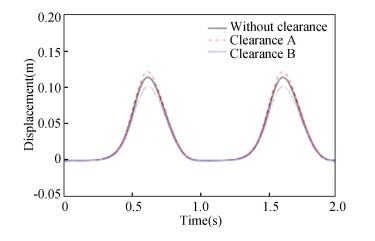
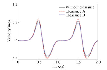
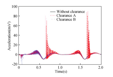
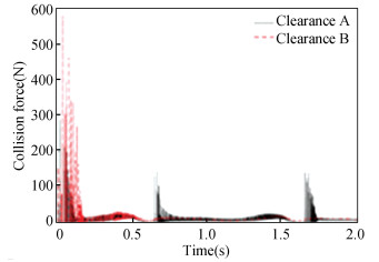
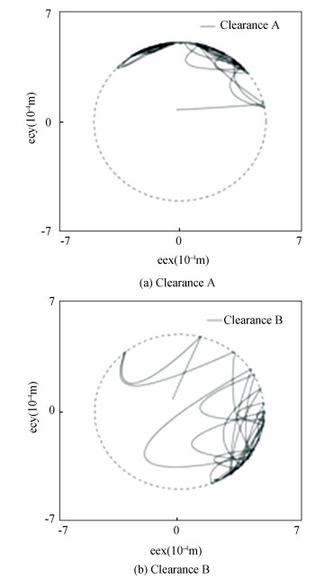
Clearance values were all 0.5 mm, and driving speeds were set to ω1=2π, ω4=-2π. Clearance A and B were analyzed separately. The following images were all obtained by MATLAB R2014. Fig. 5, 6, and 7 show the displacement, velocity, and acceleration of slider 9, respectively. The impact force and shaft center trajectory are shown in Fig. 8 and 9, respectively.
|
Fig.5 Displacement of slider 9 |
|
Fig.6 Velocity of slider 9 |
|
Fig.7 Acceleration of slider 9 |
|
Fig.8 Impact force of different clearance |
|
Fig.9 Shaft center trajectory clearance A and B |
In Fig. 9, "eex" and "eey" indicate the component of eccentricity in X, Y direction. From the displacement contrast curves in Fig. 5, the peak values of displacement curve with no clearance, with clearance A and B appeared at 0.616 s, which were 0.115 m, 0.123 m, and 0.103 m, respectively. It can be concluded that clearance affected the displacement curve; clearance A increased displacement, while clearance B reduced displacement of slider 9. Similarly, as shown in Fig. 6, the peak values of velocity curve without clearance, with clearance A and B appeared at 0.512 s, which were 0.653 m/s, 0.712 m/s, and 0.586 m/s, respectively. It can be concluded that clearance affected velocity curve; clearance A increased the speed of slider 9, while clearance B reduced the speed of slider 9. From the acceleration contrast curves of Fig. 7, it can be seen that the acceleration curve with clearance B vibrated greatly in [0 s, 0.6 s], while the acceleration curve with clearance A vibrated greatly after 0.6 s. From the analysis of Fig. 8, it can be seen that the collision force was intense in [0 s, 0.2 s]; the peak value of collision force produced by clearance A appeared at 0.018 s, the size was 289 N; the peak value of collision force produced by clearance B appeared at 0.037 s, the size was 581 N. From Fig. 9, it can be concluded that revolute joint with clearance B had larger collision range and a more chaotic shaft center trajectory.
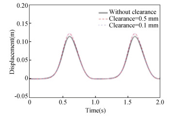
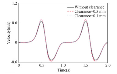
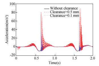
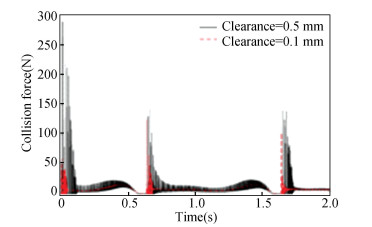
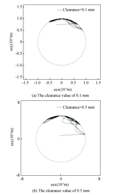
3.3 Effects of Different Clearance Value on Dynamics ResponsesTwo different clearance values were set in revolute joint A of the mechanism in this section, which were 0.1 mm and 0.5 mm, respectively, and the driving speeds were ω1=2π, ω4=-2π. Displacement, velocity, and acceleration of slider 9 are shown in Fig. 10, 11, and 12, respectively. The impact force and shaft center trajectory in the revolute joint A are shown in Fig. 13 and 14, respectively.
|
Fig.10 Displacement of slider 9 |
|
Fig.11 Velocity of slider 9 |
|
Fig.12 Acceleration of slider 9 |
|
Fig.13 Impact force in revolute joint A |
|
Fig.14 Shaft center trajectory in revolute joint A |
Displacement contrast curves in Fig. 10 show that clearance affects displacement response curve. When the clearance was located at revolute joint A, whether the clearance value was 0.5 mm or 0.1 mm, the fluctuation of displacement response curve would increase. According to Fig. 11, the vibration of velocity curve with clearance value of 0.5 mm was greater than that with clearance value of 0.1 mm. Therefore, the larger the clearance size is, the sharper the velocity vibration is. When the clearance values were 0.5 mm and 0.1 mm, the peak values of the acceleration response curves appeared at 0.64 s and 1.68 s, which were 76.2 m/s2 and 90.7 m/s2, respectively. Thus when clearance size increased, the vibration intensified. According to Fig. 13, when clearance sizes were 0.5 and 0.1 mm, peak values of collision force curves appeared at 0.018 s and 0.64 s, which were 289 N and 124 N, respectively. The larger clearance value is, the more violent the curve vibration is. From Fig. 14, when clearance size became larger, shaft center trajectory would be more chaotic.
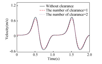
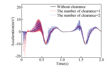
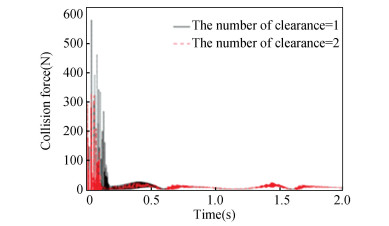
3.4 Effects of Different Numbers of Clearance in Dynamics ResponseClearance values were all 0.5 mm, and speeds were ω1=2π, ω4=-2π. Displacement, velocity, and acceleration of slider 9 are shown in Fig. 15, 16, and 17, respectively. The impact force and axis center trajectory in revolute joint B under various number of clearances are shown in Fig. 18 and 19, respectively.

|
Fig.15 Displacement of slider 9 |
|
Fig.16 Velocity of slider 9 |
|
Fig.17 Acceleration of slider 9 |
|
Fig.18 Impact force in revolute joint |

|
Fig.19 Axis center trajectory in revolute joint B |
From the displacement contrast curves of Fig. 15, it can be obtained that the peak values of displacement figure without clearance, with one clearance and two clearances appeared at 0.616 s with the value of 0.115 m, 0.103 m, and 0.109 m, respectively. According to Fig. 16, the peak velocity values without clearance, with one clearance and two clearances appeared at 0.512 s with the value of 0.653 m/s, 0.585 m/s, and 0.636 m/s, respectively. It can be concluded that the peak value of velocity curve with two clearances is larger than that with one clearance, and the vibration of velocity curve with two clearances is greater than that with one clearance. Therefore, the more the number of clearance is, the more obvious the velocity vibration is. From Fig. 17, it can be seen that the vibration of acceleration curve with one clearance is greater than that with two clearances in (0 s, 0.6 s), while the vibration of acceleration curve with two clearances is greater than that with one clearance after 0.6 s. From Fig. 18, the collision force was intense in (0 s, 0.2 s); the peak value of collision force with one clearance appeared at 0.037 s, and the size was 581 N; the peak value of collision force with two clearances appeared at 0.034 s, and the size was 330 N. Through Fig. 19, it can be obtained that the shaft center trajectory with two clearances is more stable than that with one clearance, and the impact on the mechanism is smaller.
4 Main Influence Factors of Chaos Motion in Planar MechanismNon-linear characteristic is an indispensable aspect of mechanism research, which can provide theoretical basis for selection of clearance. Chaos is an important part of it. In the present study, Poincaré mapping and phase trajectory mapping are the key to study chaos in non-linear system. Bifurcation diagram can study non-linear characteristics and analyze stability of mechanism. The above images were obtained by running the program by MATLAB for 100 cycles. In this paper, various clearance sizes and driving speeds were selected for analyzing non-linear characteristics.
4.1 Effects of Different Clearance Sizes in Non-Linear CharacteristicsThe speeds were ω1=2π, ω4=-2π, and friction coefficient was set to 0.3. Taking advantage of phase trajectory and Poincaré mappings, the effects of different clearance values were studied.
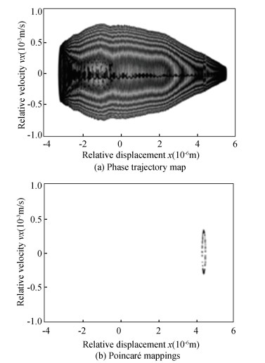
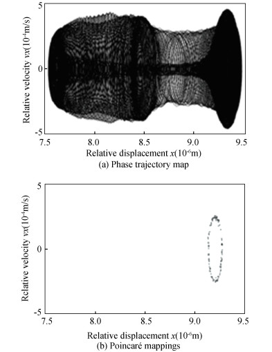
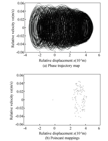
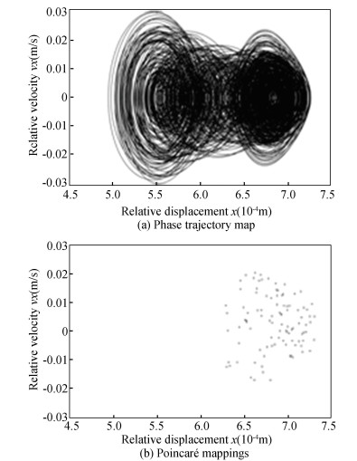
As shown in Fig. 20 and Fig. 21, when clearance value was set to 0.01 mm, Poincaré mapping became closed circle no matter it was the image of clearance A or clearance B, which shows that the mechanism was in quasi-periodic state. It can be seen in Fig. 22 and Fig. 23 that when clearance value was set to 0.8 mm, points were disorderly distributed no matter it was the image of clearance A or clearance B, so the mechanism was in chaotic state.
|
Fig.20 The phase trajectory and Poincaré mappings with clearance A with clearance value of 0.01 mm |
|
Fig.21 The phase trajectory and Poincaré map with the revolute joint B with clearance value of 0.01 mm |
|
Fig.22 The phase trajectory and Poincaré mappings of the revolute joint A with clearance value of 0.8 mm |
|
Fig.23 The phase trajectory map and Poincaré map of the revolute joint B with clearance value of 0.8 mm |
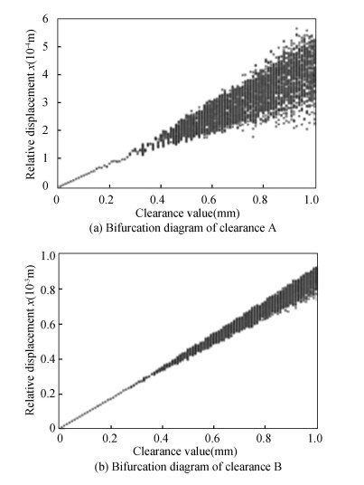
Because the bifurcation diagram studies effects of various factors in stability of mechanism better, clearance values in range of (0.01 mm, 1 mm) were selected to analyze dynamical characteristic. According to Fig. 24, it can be seen that with increasement of clearance value, motional state changed from periodic state to chaos; the chaotic phenomena were more obvious. At the same time, with increasement of clearance value, chaos in clearance A was stronger than clearance B, which shows that clearance A had a bigger influence on system.
|
Fig.24 Bifurcation diagram of different clearance values |
4.2 Effects of Different Driving Speeds in Non-Linear Characteristics
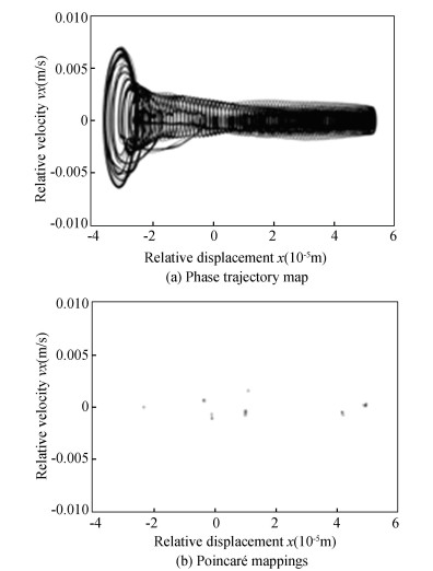
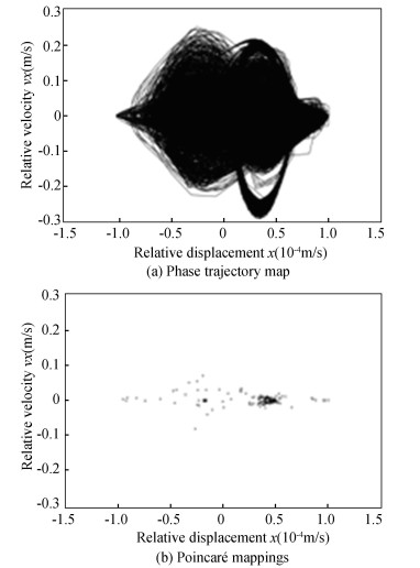
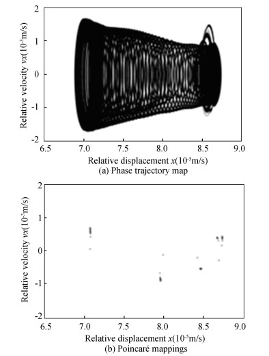
The clearance value was 0.1 mm, and friction factor was 0.3. Taking advantage of phase trajectory and Poincaré mappings, the effects of driving speeds were studied.
From Fig. 25 to Fig. 28, the phase trajectory and Poincaré map were obtained. When driving speed was 2π rad/s, Poincaré mappings points were distributed discretely, so chaotic phenomenon existed, but the range was not large. When driving speed was 3π rad/s, the number of Poincaré mappings points increased, the range of point distribution became larger, the chaotic phenomenon became obvious, and the system stability decreased.
|
Fig.25 Phase trajectory map and Poincaré mappings of the revolute joint A with driving speed of 2π (rad/s) |
|
Fig.26 Phase trajectory map and Poincaré map of the revolute joint A with driving speed of 3π (rad/s) |
|
Fig.27 Phase trajectory map and Poincaré map of the revolute joint B with driving speed of 2π (rad/s) |
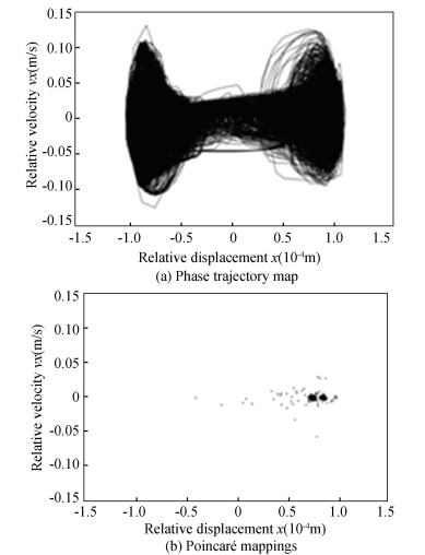
|
Fig.28 Phase trajectory map and Poincaré map of the revolute joint B with driving speed of 3π (rad/s) |
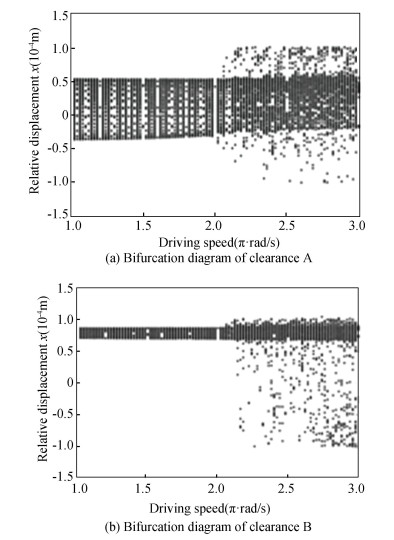
As shown in Fig. 29, the bifurcation diagrams of planar mechanism with double clearances were analyzed. The range of the driving velocities interval was chosen as (1π(rad/s), 3π (rad/s)) to study the bifurcation of non-linear characteristics. It can be seen that there were chaotic phenomena in the mechanism movement from the driving speed of 0 to 2π, but the phenomena were not very obvious and had little change. From the speed of 2π to 3π, with increase of driving speed, the chaotic phenomena were easier to see, and the stability of mechanism was also worse.
|
Fig.29 Bifurcation diagram of different driving speed |
5 Conclusions
The dynamic responses and non-linear characteristic of a planar 2-DOF mechanism with clearances were studied. The following conclusions can be drawn:
1) Normal contact force model was established by L-N model, and tangential friction model of mechanism was established by improved Coulomb friction model. Through Lagrange multiplier method, an improved dynamics model was developed.
2) Effects of different clearance position, value, and number in dynamical responses were analyzed. The effect of the clearance at different positions was different. With the increase of clearance size, peak size of dynamic response and vibration frequency increased, the shaft trajectory became more disordered, and output accuracy of the mechanism decreased. With the increase of number of clearance, peak value in dynamic response and vibration frequency increased, and the output accuracy of the mechanism decreased. It provides a reliable basis for the selection and design of mechanism clearance.
3) The impacts of different clearance and driving speed in non-linear characteristics were discussed. Taking advantage of phase diagram and Poincaré mappings, the chaotic phenomena were analyzed, and then the bifurcation diagram under various clearance sizes and different driving speeds were obtained. Those results show that with the increase of clearance value, the motion of mechanism changed from periodic state to chaotic state. The appropriate clearance value is beneficial to the stability in system. With increase of driving speed, chaotic phenomena became more obvious. So a proper reduction of the driving speed is beneficial to the stability of the mechanism.
| [1] |
Wang X P, Liu G, Ma S J, et al. Effects of clearance joint on impact dynamic characteristics of planar mechanisms. Journal of Vibration and Shock, 2017, 36(17): 74-78. (in Chinese) DOI:10.13465/j.cnki.jvs.2017.17.012 (  0) 0) |
| [2] |
Chen X L, Jiang S, Deng Y, et al. Dynamics analysis of 2-DOF complex planar mechanical system with joint clearance and flexible links. Nonlinear Dynamics, 2018, 93(1): 1009-1034. DOI:10.1007/s11071-018-4242-x (  0) 0) |
| [3] |
Salahshoor E, Ebrahimi S, Zhang Y Q. Frequency analysis of a typical planar flexible multibody system with joint clearances. Mechanism and Machine Theory, 2018, 126: 429-456. DOI:10.1016/j.mechmachtheory.2018.04.027 (  0) 0) |
| [4] |
Wang G X, Wang L. Dynamics investigation of spatial parallel mechanism considering rod flexibility and spherical joint clearance. Mechanism and Machine Theory, 2019, 137: 83-107. DOI:10.1016/j.mechmachtheory.2019.03.017 (  0) 0) |
| [5] |
Wang X P, Liu G, Ma S J, et al. Effects of restitution coefficient and material characteristics on dynamic response of planar multi-body systems with revolute clearance joint. Journal of Mechanical Science and Technology, 2017, 31(2): 587-597. DOI:10.1007/s12206-017-0111-7 (  0) 0) |
| [6] |
Chen X L, Jiang S Y. Dynamic response and chaos in planar multi-link mechanism considering revolute clearances. Archive of Applied Mechanics, 2020, 90(9): 1919-1941. DOI:10.1007/s00419-020-01704-4 (  0) 0) |
| [7] |
Tian Q, Flores P, Lankarani H M. A comprehensive survey of the analytical, numerical and experimental methodologies for dynamics of multibody mechanical systems with clearance or imperfect joints. Mechanism & Machine Theory, 2018, 122: 1-57. DOI:10.1016/j.mechmachtheory.2017.12.002 (  0) 0) |
| [8] |
Chen X L, Gao W H, Deng Y, et al. Chaotic characteristic analysis of spatial parallel mechanism with clearance in spherical joint. Nonlinear Dynamics, 2018, 94: 2625-2642. DOI:10.1007/s11071-018-4513-6 (  0) 0) |
| [9] |
Erkaya S. Experimental investigation of flexible connection and clearance joint effects on the vibration responses of mechanisms. Mechanism and Machine Theory, 2018, 121: 515-529. (  0) 0) |
| [10] |
Wang G, Liu H. Three-dimensional wear prediction of four-degrees-of-freedom parallel mechanism with clearance spherical joint and flexible moving platform. Journal of Tribology, 2018, 140(3): 031611. DOI:10.1115/1.4038806 (  0) 0) |
| [11] |
Flores P, Lankarani H M. Dynamic response of multibody systems with multiple clearance joints. Journal of Computational and Nonlinear Dynamics, 2012, 7(3): 031003. DOI:10.1115/1.4005927 (  0) 0) |
| [12] |
Ahmedalbashir M, Romdhane L, Lee J. Dynamics of a four-bar mechanism with clearance and springs - Modeling and experimental analysis. Journal of Mechanical Science and Technology, 2017, 31(3): 1023-1033. DOI:10.1007/s12206-017-0201-6 (  0) 0) |
| [13] |
Tan X, Chen G P, Sun D Y, et al. Dynamic analysis of planar mechanical systems with clearance joint based on LuGre friction model. Journal of Computational & Nonlinear Dynamics, 2018, 13(6): 061003. DOI:10.1115/1.4039877 (  0) 0) |
| [14] |
Jiang S, Chen X L. Reducing undesirable effects of clearances on dynamic and wear of planar multi-link mechanism. Nonlinear Dynamics, 2020, 100(2): 1173-1201. DOI:10.1007/s11071-020-05591-w (  0) 0) |
| [15] |
Xiang W W K, Yan S Z, Wu J N. Dynamic analysis of planar mechanical systems considering stick-slip and Stribeck effect in revolute clearance joints. Nonlinear Dynamics, 2019, 95(1): 321-341. DOI:10.1007/s11071-018-4566-6 (  0) 0) |
| [16] |
Chen X L, Li Y W, Jia Y H. Dynamic response and nonlinear characteristics of spatial parallel mechanism with spherical clearance joint. Journal of Computational and Nonlinear Dynamics, 2019, 14(4): 041010. DOI:10.1115/1.4042636 (  0) 0) |
| [17] |
Tan H Y, Hu Y J, Li L, et al. Effect of friction on the dynamic analysis of slider-crank mechanism with clearance joint. International Journal of Non-Linear Mechanics, 2019, 115: 20-40. DOI:10.1016/j.ijnonlinmec.2019.04.009 (  0) 0) |
| [18] |
Ma J, Qian L F. Modeling and simulation of planar multibody systems considering multiple revolute clearance joints. Nonlinear Dynamics, 2017, 90(3): 1907-1940. DOI:10.1007/s11071-017-3771-z (  0) 0) |
| [19] |
Wei D G, Wang Y, Jiang T, et al. Chaos vibration of pinion and rack steering trapezoidal mechanism containing two clearances. Mechanical Systems and Signal Processing, 2017, 92: 146-155. DOI:10.1016/j.ymssp.2017.01.019 (  0) 0) |
| [20] |
Hou Y L, Wang Y, Jing G N, et al. Chaos and impact phenomena of a RU-RPR decoupled parallel mechanism containing clearance. Journal of Vibration and Shock, 2017, 36(1): 215-222, 239. (in Chinese) DOI:10.13465/j.cnki.jvs.2017.01.032 (  0) 0) |
| [21] |
Li Y Y, Wang C, Huang W H. Dynamics analysis of planar rigid-flexible coupling deployable solar array system with multiple revolute clearance joints. Mechanical Systems and Signal Processing, 2019, 117: 188-209. DOI:10.1016/j.ymssp.2018.07.037 (  0) 0) |
| [22] |
Marques F, Isaac F, Dourado N, et al. A study on the dynamics of spatial mechanisms with frictional spherical clearance joints. Journal of Computational and Nonlinear Dynamics, 2017, 12(5): 051013. DOI:10.1115/1.4036480 (  0) 0) |
| [23] |
Askari E, Flores P, Dabirrahmani D, et al. Dynamic modeling and analysis of wear in spatial hard-onhard couple hip replacements using multibody systems methodologies. Nonlinear Dynamics, 2015, 82(1-2): 1039-1058. DOI:10.1007/s11071-015-2216-9 (  0) 0) |
| [24] |
Koshy C S, Flores P, Lankarani H M. Study of the effect of contact force model on the dynamic response of mechanical systems with dry clearance joints: computational and experimental approaches. Nonlinear Dynamics, 2013, 73(1-2): 325-338. DOI:10.1007/s11071-013-0787-x (  0) 0) |
| [25] |
Erkaya S, Doğan S, Ulus Ş. Effects of joint clearance on the dynamics of a partly compliant mechanism: numerical and experimental studies. Mechanism and Machine Theory, 2015, 88: 125-140. DOI:10.1016/j.mechmachtheory.2015.02.007 (  0) 0) |
| [26] |
Zheng X D, Zhang R S, Wang Q. Comparison and analysis of two Coulomb friction models on the dynamic behavior of slider-crank mechanism with a revolute clearance joint. Applied Mathematics and Mechanics: English Edition, 2018, 39: 1239-1258. DOI:10.1007/s10483-018-2371-9 (  0) 0) |
| [27] |
Chen X L, Jiang S, Wang S Y, et al. Dynamics analysis of planar multi-DOF mechanism with multiple revolute clearances and chaos identification of revolute clearance joints. Multibody System Dynamics, 2019, 47: 317-345. DOI:10.1007/s11044-018-09654-0 (  0) 0) |
| [28] |
Jiang S, Chen X L, Deng Y. Dynamic response analysis of planar multilink mechanism considering wear in clearances. Shock and Vibration, 2019, 2019: 5389732. DOI:10.1155/2019/5389732 (  0) 0) |
 2021, Vol. 28


