2. School of Aeronautics and Astronautics, Harbin Institute of Technology, Harbin 150001, China;
3. Engineering College, Northeast Agricultural University, Harbin 150030, China
Ceramic matrix composites (CMCs) exhibit high specific strength and stiffness, superior damage tolerance, low thermal expansion coefficient, and excellent oxidation resistance at high temperatures. Because of these characteristics and low density, CMCs have become attractive materials for aerospace propulsion system components and space vehicle hot structures[1-2]. To realize their successful applications, CMCs are often connected with superalloy components by mechanical joints. Among the existing joint methods, bolted joint has attracted much attention owing to its advantages of high load transfer capability, simplicity in assembling and disassembling, and excellent environmental damages tolerance. In high temperature service conditions, CMC and superalloy bolted joint structures are subjected to combined thermal and mechanical loads. The thermal expansion mismatch between CMC and superalloy plates will cause complex thermal stress and strain distributions at hole-edge area and changes in assembly parameters of the joint, such as pre-load loosening and variation of bolt-hole clearance[1-2]. These effects might lead to early damage of joint structure, which will endanger the structural integrity and load carrying capacity of aircraft components. Most of previous research lied emphasis on the development of the constituent modeling of CMC[3-13] and failure behaviors of their joint structures[14-17]. Little research can be found to examine the early thermo-structural behaviors of CMC bolted joint under thermal loads. In the present paper, transient heat transfer and thermo-structural analysis of C/SiC composite and superalloy bolted joint are carried out by using a commercial FEA software ABAQUS. The stress distribution at hole-edge areas and changes of assembling parameters of CMC bolted joints under temperature rises are discussed.
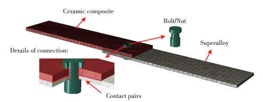
1 Analysis Methods 1.1 Heat Transfer AnalysisOne of the goals of performing heat transfer analysis is to determine transient thermal responses within the CMC bolted joint at various heating durations. Another goal is to impose the obtained temperature distribution at each time as thermal loads for subsequent structural analysis. 2D plain-woven C/SiC composite to GH4169 superalloy with single-bolt and single-lap joint structure was used for this study, and the geometry and dimensions of the joint are shown in Fig. 1. Both the C/SiC composite plate and the GH4169 alloy plate were 120 mm long, with 30 mm griping length. The thicknesses of the CMC plate and the GH4169 alloy plate were 3.0 mm and 2.0 mm, respectively. The two plates were assembled together using a 6.0 mm diameter bolt made of GH4141 alloy. The thermophysical properties of the 2D woven C/SiC composite, GH4169 and GH4141 alloy provided by the material supplier are listed in Tables 1-3. Finite element model was established to simulate transient heat transfer of C/SiC composite- superalloy bolted joint via Abaqus/standard software (Fig. 2). Heat transfer hexahedron element (DC3D8) with linear eight nodes and mesh refinement was used to model the composite laminates, superalloy plate, and mechanical fastener. In total, five contact pairs were defined, including upper surface of composite plate to bolt, inner surface of hole in composite plate to bolt, inner surface of hole in superalloy plate to bolt, composite plate to superalloy plate, and lower surface of superalloy to nut. Ideal contact was assumed for all considered contact surfaces. Constant temperature loads 150 ℃, 300 ℃, 450 ℃, 600 ℃, and 750 ℃ were imposed on the top surface of composite panel and outer surface of bolt head depending on analysis scenarios. Natural convection was applied on the rest surfaces of the joint structure with film coefficient of 0.01 mW/(mm2·℃). Both initial temperature of the entire structure and the ambient temperature were set as 25 ℃.

|
Fig.1 Specimen geometry configuration of 2D C/SiC composite-superalloy bolt joint structure (mm) |
| Table 1 Thermophysical properties of 2D plain-woven C/SiC composite |
| Table 2 Thermophysical properties of superalloy(thermal conductivity) |
| Table 3 Thermophysical properties of superalloy(specific heat capacity and density) |
|
Fig.2 Finite element model of 2D C/SiC composite-superalloy bolted joint structure for thermal analysis |
1.2 Thermo-Structural Analysis
Inthe thermo-structural analysis of the CMC bolted joint structure, the mechanical properties for the three involved materials are listed in Tables 4-7. Friction coefficient of 0.3 was imposed for all set contact pairs as described above. To simulate assembly torque, pre-load was applied on the metallic bolt using bolt load function in ABAQUS. In light of lower compressive strength and thermal expansion coefficient of composite, interference is possibly generated between superalloy bolt and CMC panel for neat-fit bolted joint as the temperature elevates, which might lead to hole-edge failure of composite panel. To avoid such initial failure, a 0.7% clearance fit between bolt and two panels was set for all the cases in this study. The DC3D8 element used for heat transfer analysis was converted to 8-node reduced-integration C3D8R elements with hourglass control for the discretization of structural model. The non-overlapped end of the superalloy plate was fully constrained. In order to observe changes of uniform bolt-hole clearance at various temperatures, no mechanical load was applied on the end of the composite plate. The temperature distribution results (.ODB file) from the above thermal analysis was imposed on each node of finite element mesh as predefined field to implement a subsequent thermo-mechanical coupled analysis of the CMC bolted joint. Based on the developed model, the thermal stress distribution in joint area, changes of pre-load, and bolt-hole clearance for the studied bolted joint under thermal load were obtained for further discussion.
| Table 4 Mechanical properties of 2D woven C/SiC composite material |
| Table 5 Mechanical properties of superalloy(Young's moduli) |
| Table 6 Mechanical properties of superalloy(Poisson's ratio) |
| Table 7 Mechanical properties of superalloy(Coefficient of thermal expansion) |
2 Results and Discussion 2.1 Transient Thermal Responses of the Bolted Joint
When the structure of the C/SiC composite and superalloy bolted joint was subjected to the thermal loading conditions as mentioned above, it experienced from transient state to steady state as the heating period was prolonged. For 750 ℃ heat load, the simulated temperature contours of the joint structure at different time durations are displayed in Fig. 3. Variations of average temperature at upper surface and lower surface of the composite plate and superalloy plate with heating period are plotted in Fig. 4. As can be seen from Figs. 3-4, for the whole structure, the temperatures at the plotted locations varied dramatically in the first 100 s, while they changed less within 100-200 s. The temperatures gradually became constant and reached steady state when the heating duration was longer than 1288 s. The temperature contour maps at steady state for all components of the joint structure are illustrated in Fig. 5. According to Fig. 5(b), the minimum temperature is 659.1 ℃ for the CMC plate, which was at the lower surface of the overlapped end of both plates. However, large temperature gradient could be observed in the superalloy plate, as plotted in Fig. 5(c). Due to convection cooling effect, the lowest value of 166 ℃ occurred on the right end of the superalloy panel.

|
Fig.3 Temperature contour map of the CMC and superalloy bolted joint structure at different heating periods |

|
Fig.4 Variation of average temperature at different locations for the studied CMC and superalloy bolted joint with time duration |

|
Fig.5 Temperature contour map of the CMC and superalloy bolted joint structure at steady state condition |
2.2 Thermal Stress and Assembly Parameters Variations of the Joint
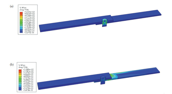
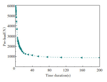
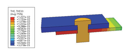
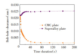
According to the results of thermal analysis, the CMC and superalloy bolted joint structure experienced significant variation of temperature distribution before reaching a steady state. To gain further insight into the effect of temperature rise on structural behavior, the stress field of the joint structure with 6000 N pre-load and 0.7% bolt-hole clearance was firstly analyzed. The stress contour maps for the bolted joint before and after imposing steady state temperature field under thermal load of 750 ℃ are displayed in Fig. 6. A distinct decline in the equivalent stress could be observed for the CMC and superalloy bolted joint, and the maximum value was reduced to 128.9 MPa after imposing thermal load of 750 ℃, compared with the value of 503.5 MPa at room temperature. The pre-load for the studied joint structure at various thermal loading time is plotted in Fig. 7. It shows that during the first 200 s, the pre-load decreased sharply from 6000 N to 871 N, accounting for 85.5% falling as the heating time prolonged. The decrease can be explained by thermal expansion mismatch between CMC and high temperature superalloy. According to the thermal strain contour map for the bolted joint subjected to 750 ℃ (Fig. 8), higher thermal expansion coefficient of bolt and superalloy plate resulted in more substantial thermal stain and greater elongation of superalloy bolt along thickness direction than that of CMC, which undoubtedly decreased the pre-load. This decline in pre-load contributes to stress relaxation, namely the decrease in maximum equivalent stress for the joint structure as mentioned above. The variation of bolt-hole clearance induced by the imposed temperature load is demonstrated in Fig. 9, in which the bolt-hole clearance for composite plate reduced to 0.0012 mm at the heating duration from 0 s to 200 s. On the contrary, the clearance for the superalloy plate increased to 0.025 mm from the original value of 0.021 mm. This is an indication that no contact occurred between the plates and the bolt even after being heated at 750 ℃ for 200 s, if 0.7% initial bolt-hole clearance was given for analysis.
|
Fig.6 Equivalent stress contour map of the CMC and superalloy bolted joint before (a) and after (b) imposing temperature load of 750 ℃ |
|
Fig.7 Variation of pre-load with heating time duration for the studied CMC and superalloy joint structure |
|
Fig.8 Thermal strain contour map along thickness direction for the CMC and superalloy bolted joint subjected to 750 ℃ |
|
Fig.9 Variation of bolt-hole clearance with time duration for the studied CMC and superalloy joint structure |
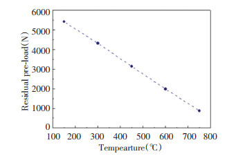
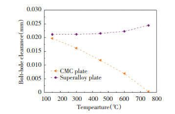
Variations of the pre-load and bolt-hole clearance with the imposed hot-side temperature are shown in Figs. 10 and Fig. 11, respectively. As demonstrated, large variations in assembly parameters occurred in the first 40 s. For the given 0.7% clearance, the pre-load decreased from 6000 N at room temperature to 5416 N for thermal load 150 ℃, 3134 N for 450 ℃, and 871 N for 750 ℃, and the decrease at 750 ℃ could be up to 85.5%. With the increase of temperature, a slight increase in the bolt-hole clearance for superalloy plate could be observed from 0.021 mm at room temperature to 0.024 mm at 750 ℃. However, the clearance for composite plate decreased to 0.012 mm at 450 ℃ and 3.10×10⁻⁴ mm at 750 ℃. Remarkable decline of 94.7% in the bolt-hole clearance at 750 ℃ meant that 0.7% initial assemble clearance at room temperature would be changed to neat-fit condition as the bolted joint reached thermal equilibrium for the considered heating boundaries. The adverse varying trends in the clearance for the two plates could be reduced to difference in thermal expansion coefficients of materials. Compared with the superalloy, the C/SiC composite possesses lower thermal expansion coefficient, thus the gap between the bolt and hole became narrow. On the contrary, the slight increase in clearance between the bolt and the superalloy plate can be attributed to the close values of thermal expansion of the two metallic parts.
|
Fig.10 Variation of residual pre-load with imposed hot-side temperature for the studied CMC and superalloy bolted joint structure |
|
Fig.11 Variation of bolt-hole clearance with imposed hot-side temperature for the studied CMC and superalloy bolted joint structure |
3 Conclusions
To observe thermo-mechanical behavior and variations of assembly parameters of single-lap C/SiC composite and superalloy bolted joint under elevated temperatures, heat transfer analysis was firstly carried out to calculate transient temperature distribution at each heating time, which was then imposed on the finite element model of the joint as predefined field for subsequent thermo-structural analysis by using a commercial FEA software ABAQUS. Results showed that pre-load decreased dramatically with the increase of imposed time duration and hot side temperature due to the thermal expansion mismatch between CMC and high temperature superalloy. The bolt-hole clearance for composite plate induced by the imposed thermal load decreased, whereas the clearance for superalloy plate increased with the rise of temperature. This research would establish foundation to further reveal the effect of thermal loading on damage mechanism and failure load for CMC bolted joint applied at high temperatures in the future work.
| [1] |
Naslain R. Design, preparation and properties of non-oxide CMCs for application in engines and nuclear reactors: An overview. Composites Science and Technology, 2004, 64(2): 155-170. DOI:10.1016/S0266-3538(03)00230-6 (  0) 0) |
| [2] |
Böhrk H, Beyermann U. Secure tightening of a CMC fastener for the heat shield of re-entry vehicles. Composite Structures, 2010, 92(1): 107-112. DOI:10.1016/j.compstruct.2009.07.002 (  0) 0) |
| [3] |
Marcin L, Maire J-F, Carrère N, et al. Development of a macroscopic damage model for woven ceramic matrix composites. International Journal of Damage Mechanics, 2011, 20: 939-957. DOI:10.1177/1056789510385259 (  0) 0) |
| [4] |
Aubard X, Lamon J, Allix O. Model of the nonlinear mechanical behavior of 2D SiC-SiC chemical vapor infiltration composites. Journal of the American Ceramic Society, 1994, 77(8): 2118-2126. DOI:10.1111/j.1151-2916.1994.tb07106.x (  0) 0) |
| [5] |
Gao X G, Li L, Song Y D. A temperature-dependent constitutive model for fiber-reinforced ceramic matrix composites and structural stress analysis. International Journal of Damage Mechanics, 2014, 23(4): 507-522. DOI:10.1177/1056789513500296 (  0) 0) |
| [6] |
Li J, Jiao G Q, Wang B, et al. A non-linear damage constitutive model for 2D woven C/SiC composite material and its application. Acta Materiae Compositae Sinica, 2013, 30(1): 165-171. (in Chinese) DOI:10.13801/j.cnki.fhclxb.2013.01.034 (  0) 0) |
| [7] |
Evans A G, Domergue J M, Vagaggini E. Methodology for relating the tensile constitutive behavior of ceramic‐matrix composites to constituent properties. Journal of the American Ceramic Society, 1994, 77(6): 1425-1435. DOI:10.1111/j.1151-2916.1994.tb09739.x (  0) 0) |
| [8] |
Murthy P L N, Chamis C C, Mital S K. Computational simulation of continuous fiber-reinforced ceramic matrix composites behavior. NASA Technical Paper 3602, 1997. https://ntrs.nasa.gov/search.jsp?R=19960047537.
(  0) 0) |
| [9] |
Chaboche J L, Maire J F. New progress in micromechanics-based CDM models and their application to CMCs. Composites Science and Technology, 2001, 61(15): 2239-2246. DOI:10.1016/S0266-3538(01)00118-X (  0) 0) |
| [10] |
Ismar H, Schröter F, Streicher F. Influence of the fiber volume fraction and the fiber Weibull model on the behavior of 2D woven SiC/SiC-A finite element simulation. Acta Mechanica, 2001, 149(1-4): 41-54. DOI:10.1007/BF01261662 (  0) 0) |
| [11] |
Mital S K, Murthy P L N, Chamis C C. Simplified micromechanics of plain weave composites. Journal of Advanced Materials-Covina, 2001, 33(3): 10-17. https://ntrs.nasa.gov/archive/nasa/casi.ntrs.nasa.gov/19960017575.pdf
(  0) 0) |
| [12] |
Solti J P, Mall S, Robertson D D. Modeling damage in unidirectional ceramic-matrix composites. Composites Science and Technology, 1995, 54(1): 55-66. DOI:10.1016/0266-3538(95)00041-0 (  0) 0) |
| [13] |
Sadowski T, Marsavina L. Multiscale modelling of two-phase ceramic matrix composites. Computational Materials Science, 2011, 50(4): 1336-1346. DOI:10.1016/j.commatsci.2010.04.011 (  0) 0) |
| [14] |
Yang C P, Jiao G Q, Wang B, et al. Damage-based failure theory and its application to 2D-C/SiC composites. Composites Part A: Applied Science and Manufacturing, 2015, 77: 181-187. DOI:10.1016/j.compositesa.2015.07.003 (  0) 0) |
| [15] |
Li G D, Wu X F, Zhang C R, et al. Theoretical simulation and experimental verification of C/SiC joints with pins or bolts. Materials and Design, 2014, 53: 1071-1076. DOI:10.1016/j.matdes.2013.08.001 (  0) 0) |
| [16] |
Mei H, Cheng L F, Ke Q Q, et al. High-temperature tensile properties and oxidation behavior of carbon fiber reinforced silicon carbide bolts in a simulated re-entry environment. Carbon, 2010, 48(11): 3007-3013. DOI:10.1016/j.carbon.2010.01.056 (  0) 0) |
| [17] |
Zhao L B, Yang W, Cao T C, et al. A progressive failure analysis of all-C/SiC composite multi-bolt joints. Composite Structures, 2018, 202: 1059-1068. DOI:10.1016/j.compstruct.2018.05.029 (  0) 0) |
 2021, Vol. 28


