2. State Key Lab of Mechanical System and Vibration, Shanghai Jiao Tong University, Shanghai 200240, China;
3. College of Mechanical and Electrical Engineering, Jiaxing University, Jiaxing 314001, Zhejiang, China
Generally, flexible mechanism is a monolithic structure that generates a smooth motion due to its structural deformation[1-2]. Owing to the advantages of frictionless working and lack of lubrication, flexible mechanism can perform with great potential in current and future precision engineering such as micro-grippers, micro positioning stages, and micro/nano scale manipulators[3-4]. As for flexure-based mechanism, flexure hinge was one of the basic function units. Practically, most of flexible mechanisms adopt a flexible linkage as the basic design component. Therefore, for a flexible mechanism, the operating principle depends on the configuration of the flexible linkages, and the mechanical performances are determined by the profiles of the flexure hinges[5-7].
Flexible mechanisms constructed with several-stage flexible linkage have been developed to realize the maximized mechanical performance. The Scott-Russell mechanism[8], leverage mechanism[9], and bridge-type mechanism[10]are the popular types of flexure-based amplification mechanisms in the form of flexible linkage. Micro grippers and micro manufactures mechanism take advantage of several-stage amplifies[11-12]. As for several-stage flexible linkage, the previous-stage linkage is affected by the next-stage linkage, especially in terms of input stiffness. It means that the next-stage linkage is identical to an external load applied at the previous-stage. Hence, the external load and its corresponding effects have to be considered in modeling and investigation[7, 13]. But most of the previous studies focused on the performances of the flexible linkage in an ideal condition where there is no external load[14-15]. The elastic beam theorem (EBT) can perform with a higher precision than the Pseudo-Rigid-Body model (PRBM)[16]. Luo et al.[17]verified that EBT is superior to PRBM regarding the displacement amplification ratio of a bridge-type mechanism.
The objectives of this study are to derive the displacement amplification, driving force, and work efficiency of a flexible linkage under motion constrains, and gain a deep insight into the effects of material property and external loads. These effects were demonstrated by taking a bridge-type mechanism as an example. By applying the obtained derivations and solutions, a flexible mechanism with a two-stage linkage was developed and optimized for a micro suction cup that achieved a negative pressure adsorption.
The content of this paper is as follows. In Section 1, an elastic modeling method is proposed to investigate a generic flexible linkage and a bridge arm from the perspectives of output displacement, driving force, and work efficiency. In Section 2, a comparison with the finite element method (FEM) simulations is conducted to prove the validity of the proposed modeling method and demonstrate the effects of the external load, geometric parameters, and material property. A suction cup with several flexible linkages in hybrid configuration is presented in Section 3. The discussions pertaining to the obtained results are given in detail in Section 4. Finally, Section 5 summarizes the conclusions of this work.
1 Modeling on a Flexure-Based Linkage 1.1 Generic Flexible LinkageAn elastic modeling method was developed to evaluate the kinematic characteristics of a generic flexible linkage under motion constrains and an external load. A generic flexible linkage is a rigid linkage connecting with flexure hinges, in which the axial direction of the flexure hinges is collinear to that of the rigid linkage. In this paper, motion constrains refer to the fact that both ends are constrained and they move along different directions. Moreover, the external load is defined as any force resisting the output displacement and is less than its own block force, which guarantees that the external load does the negative work.
The flowing derivations were developed based on the assumptions that the deformation conforms to the small deformation and occurs only in the flexure hinges. Generally, the equations that demonstrate the mechanical stiffness or compliance are complex. In order to simplify the analytic derivation and realize a generic formula, the beam flexure hinge (Fig. 1) and the 3-DOF compliance matrix C were employed in this work.
| $ \boldsymbol{X}=\boldsymbol{C} \cdot \boldsymbol{F} $ | (1) |

|
Fig.1 Schematic view of a beam flexure hinge |
where
| $ \boldsymbol{X}=\left[\begin{array}{ccc} \Delta x & \Delta y & \Delta \gamma \end{array}\right]^{\mathrm{T}} $ | (2) |
| $ \boldsymbol{F}=\left[\begin{array}{lll} F_{x} & F_{y} & M_{z} \end{array}\right]^{\mathrm{T}} $ | (3) |
The compliance matrix can be obtained based on the Euler-Bernoulli beam theory, where the shearing in the flexure hinges is ignored, as follows:
| $ \begin{array}{l} \boldsymbol{C}=\left[\begin{array}{ccc} C_{x-F} & 0 & 0 \\ 0 & C_{y-F} & C_{y-M} \\ 0 & C_{\theta-F} & C_{\theta-M} \end{array}\right]= \\ \ \ \ \ \ \ \ \ \ \ \ \ \ \ \ \ \ \ {\left[\begin{array}{ccc} \frac{l}{E b t} & 0 & 0 \\ 0 & \frac{4 l^{3}}{E b t^{3}} & -\frac{6 l^{2}}{E b t^{3}} \\ 0 & -\frac{6 l^{2}}{E b t^{3}} & \frac{12 l}{E b t^{3}} \end{array}\right]} \end{array} $ | (4) |
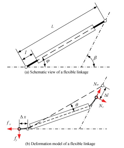
As shown in Fig. 2, owing to the motion constrain, an input displacement Δx caused a generic flexible linage rotation θ. Correspondingly, an output displacement of Δl was produced.
|
Fig.2 Model of generic flexible linkage under motion constrains |
Other parameters in the model are as follows. The included angle between the input and the output is β and that between the direction of the input displacement and the axial direction of the flexure hinges is φ (φ≤β). The length of the flexure hinges is l and the length of the linkage is L. fx denotes the driving force, Nσ denotes the external force, and fy and Nτ are the support forces. According to the force equilibrium, an equation exists which describes the relationship between input and output in terms of forces as
| $ \left\{\begin{array}{l} f_{x}=N_{\sigma} \cos \beta+N_{\tau} \sin \beta \\ f_{y}=N_{\sigma} \sin \beta-N_{\tau} \cos \beta \end{array}\right. $ | (5) |
The direction of fx is identical to the input displacement, as the direction of Nσ is opposite to that of the output displacement Δl. The axial force at the flexure hinges can be expressed as
| $ F_{a}=N_{\sigma} \cos (\beta-\varphi)+N_{\tau} \sin (\beta-\varphi) $ | (6) |
Due to the mechanical symmetry, the strain/stress of the flexure hinges is identical and symmetrical. Hence, the deflection angle of the flexure hinges is also identical, which is derived by Eqs. (5)-(6) as
| $ \theta=\frac{1}{2} C_{\theta-M} L\left[N_{\tau} \cos (\beta-\varphi)-N_{\sigma} \sin (\beta-\varphi)\right] $ | (7) |
Furthermore, the equations that formulate the motion constrains are obtained as follows:
| $ \Delta x=\Delta l \cos \beta+\theta L \sin \varphi+2 C_{x-F} F_{a} \cos \varphi $ | (8) |
| $ \Delta l \sin \beta+2 C_{x-F} F_{a} \sin \varphi=\theta L \cos \varphi $ | (9) |
By combining Eqs. (5)-(9), the output displacement Δl subject to an external load is derived as
| $ \Delta l=\frac{N_{\sigma}\left(R_{1} R_{4}-R_{2} R_{3}\right)+R_{1} \Delta x}{R_{1} \cos \beta+R_{3} \sin \beta} $ | (10) |
where
| $ \left\{\begin{array}{l} R_{1}=C_{\theta-M} L^{2} \cos \varphi \cos (\beta-\varphi) / 2-2 C_{x-F} \sin \varphi \sin (\beta-\varphi) \\ R_{2}=C_{\theta-M} L^{2} \cos \varphi \sin (\beta-\varphi) / 2+2 C_{x-F} \sin \varphi \cos (\beta-\varphi) \\ R_{3}=C_{\theta-M} L^{2} \sin \varphi \cos (\beta-\varphi) / 2+2 C_{x-F} \cos \varphi \sin (\beta-\varphi) \\ R_{4}=C_{\theta-M} L^{2} \sin \varphi \sin (\beta-\varphi) / 2-2 C_{x-F} \cos \varphi \cos (\beta-\varphi) \end{array}\right. $ | (11) |
Meanwhile, a driving force fx is essential to go with the applied input displacement to have the flexible linkage produce the output, which is formulated as
| $ f_{x}=N_{\sigma} \cos \beta+\frac{N_{\sigma}\left(R_{2} \cos \beta+R_{4} \sin \beta\right)+\Delta x \sin \beta}{R_{1} \cot \beta+R_{3}} $ | (12) |
In a several-stage flexible mechanism, the other type of the external load is with a constant stiffness of k[18-19]and is expressed as
| $ N_{\sigma}=k \Delta l $ | (13) |
Therefore, the output displacement and the driving force are rewritten as follows:
| $ \Delta l^{\mathrm{e}}=\frac{R_{1}}{R_{1} \cos \beta+R_{3} \sin \beta-k\left(R_{1} R_{4}-R_{2} R_{3}\right)} \Delta x $ | (14) |
| $ f_{x}^{\mathrm{e}}=\frac{\sin ^{2} \beta+k\left(R_{1} \cos \beta+R_{2} \sin \beta\right)}{R_{1} \cos \beta+R_{3} \sin \beta-k\left(R_{1} R_{4}-R_{2} R_{3}\right)} \Delta x $ | (15) |
where the superscript e denotes the performances subject to an elastic force.
When β = 0 or π, the input is collinear to the output, and this flexible linkage is equivalent to a prismatic pair. When β = π/2 the output is vertical to the input, and it is identical to a bridge-type mechanism.
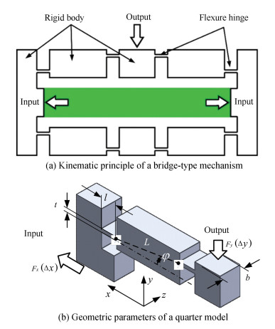
1.2 Bridge-Type MechanismA common type of the bridge-type mechanism is in the double symmetrical structure. As shown in Fig. 3, a horizontal piezoelectric actuator was employed to produce a vertical output displacement. Because of the double symmetry, it is sufficient to perform the analysis only on a quarter portion. Fig. 3(b) presents a quarter model, where φ is the initial inclination angle of the bridge arm, t is the thickness of the flexure hinge, L is the length of the bridge arm, l is the length of the flexure hinge, and b is the structural width.
|
Fig.3 Schematic of the bridge-type mechanism |
As shown in Fig. 4, the kinematic principle of the bridge arm conformed to that of the generic flexible linkage. The bridge-type mechanism that requires a driving force Fx subjected to the input displacement Δx, and the bridge arm correspondingly rotated by θ. Consequently, the bridge-type mechanism produced an output displacement Δy under an external load Fy. According to motion constrains, the input displacement and the output displacement are expressed as a function of the rotational motion of the bridge arm and the axial deformation as follows:
| $ \left\{\begin{array}{l} \Delta x=\theta \operatorname{Lsin} \varphi+2 C_{x-F} F_{x} \\ \Delta y=\theta(L \cos \varphi+l)+2 C_{y-F} F_{y}+C_{y-M} L\left(F_{x} \sin \varphi+F_{y} \cos \varphi\right) \end{array}\right. $ | (16) |

|
Fig.4 Working principle of the bridge arm |
Based on Eq. (7), the angular deflection θ of the bridge arm is obtained as
| $ \theta=\frac{1}{2} C_{\theta-M} L\left(F_{x} \sin \varphi+F_{y} \cos \varphi\right)+C_{y-M} F_{y} $ | (17) |
1) Output displacement.
By combining Eqs. (16)-(17), the input displacement subject to a constant load can be derived as
| $ \Delta y^{\mathrm{c}}=\frac{a_{11} a_{22}-a_{12} a_{21}}{a_{11}} f_{y}+\frac{a_{12}}{a_{11}} \Delta x $ | (18) |
where a11, a12, a21, and a22 are the complicated factors, as presented in the Appendix. The superscript c indicates the case under a constant load.
When an external load with a constant stiffness of k is applied, the output displacement is rewritten as
| $ \Delta y^{\mathrm{e}}=\frac{a_{21}}{a_{11}-k\left(a_{11} b_{22}-a_{12} a_{21}\right)} \Delta x $ | (19) |
The displacement amplification ratio is the absolute value of the ratio of the output displacement to the input displacement, which is derived based on Eqs. (18)-(19), as follows:
| $ R_{d}^{\mathrm{c}} =\left|\frac{a_{11} a_{22}-a_{12} a_{21}}{a_{11}} \frac{f_{y}}{\Delta x}+\frac{a_{12}}{a_{11}}\right| $ | (20) |
| $ R_{d}^{\mathrm{e}} =\left|\frac{a_{21}}{a_{11}-k\left(a_{11} b_{22}-a_{12} a_{21}\right)}\right| $ | (21) |
2) Driving force.
According to Eqs. (12) and (15), the driving force under different loads is derived by combining Eqs. (17)-(19) as follows:
| $ f_{x}^{\mathrm{c}}=\frac{\Delta x}{a_{11}}-\frac{a_{21}}{a_{11}} f_{y} $ | (22) |
| $ f_{x}^{\mathrm{e}}=\frac{1-a_{22} k}{a_{11}-k\left(a_{11} a_{22}-a_{12} a_{21}\right)} \Delta x $ | (23) |
3) Work efficiency.
The total work is the driving work supplied by the piezoelectric actuator and is transformed into two parts: its own elastic potential energy and the kinematic work. For the quasi-static state, the kinematic work is identical to the output work to drive the external load. Hence, the work efficiency in this paper is defined as the percentage rate of the kinematic work, which is obtained by combining Eqs. (18)-(23) as follows:
| $ \eta^{\mathrm{c}}=\frac{\left(a_{11} a_{22}-a_{12} a_{21}\right) f_{y}+a_{21} \Delta x}{\Delta x\left(\Delta x-a_{12} f_{y}\right)} f_{y} \times 100 \% $ | (24) |
| $ \eta^{\mathrm{e}}=\frac{k a_{11} a_{21}^{2}}{\left(a_{11}-k a_{11} a_{22}\right)\left[a_{11}-k\left(a_{11} a_{22}-a_{12} a_{21}\right)\right]} \times 100 \% $ | (25) |
The commercial software ANSYS Workbench was utilized to validate the proposed elastic model through FEM simulation. Meanwhile, effects of material properties and geometric parameters on the performances of a bridge arm under external load were further investigated. The reference parameters are listed in Table 1, which are similar to those in Ref. [20]. Structural steel (ST) and aluminum alloy (AL) were employed in the following simulation.
| Table 1 Geometric parameters of the bridge arm |
2.1 Effects of the Materials
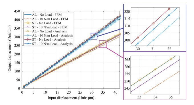
Fig. 5 depicts the output displacement subject to the input displacement, in which the bridge arm performed with different materials under different loads. It is noteworthy that the bridge arm performed with excellent linearity in terms of output displacement. Similar to the solutions in previous studies[20-21], the material property had no effect on the output displacement and the displacement amplification ratio, only in the case of no external load. Under the same external load, the output displacement decreased, and the decreased quantity was positively relevant to the inverse of the Young's modulus. The higher the Young's modulus was, the stronger the load capacity of the bridge arm was, and the larger the output displacement was subject to the identical input displacement and load.
|
Fig.5 Output displacement subject to different materials |
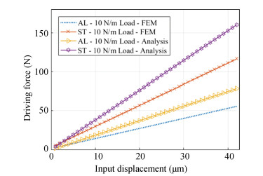
Fig. 6 indicates that the driving force of a bridge arm was linear to both the input displacement and the mechanical Young's modulus. Meanwhile, the increased quantity in the driving force was positively related to the external load, as well as the equivalent stiffness of the load.
|
Fig.6 Driving force subject to different materials |
Based on the above definition and analytic derivations, it can be found that the external load improved the work efficiency of the bridge arm. According to Fig. 7, the lower the Young's modulus is, the higher the work efficiency of the bridge arm is. When the external load was constant, the work efficiency decreased with the increase in the input displacement. When the external load was elastic, the work efficiency remained constant with respect to various input displacements. As shown in Fig. 7(b), the elastic analysis was different from the two curves depicted by the FEM simulations because of the limit of the data accuracy in the FEM calculation.

|
Fig.7 Work efficiency subject to different materials |
2.2 Effects of the Geometric Parameters
For a flexible mechanism with flexure hinges, the geometrics of the flexure hinges are critical and can directly determine the bending compliance and the structural stiffness. Based on EBT, the decrease in thickness and the increase in length can lead to the increase in the bending compliance of a beam flexure hinge. According to Figs. 8(a)-(b), the output displacement increased with the increase in the bending compliance of the flexure hinges. The compliance of the flexure hinges led to the decrease in the structural load capacity. Moreover, the bridge arm became more susceptive to the load in terms of displacement amplification, and the displacement amplification ratio was even degenerated. In addition, the decrease in the initial angle of the bridge arm indicates the decrease of the structural stiffness and the loading capacity, which led to the increase in the output displacement.

|
Fig.8 Output displacement subject to various geometric parameters |
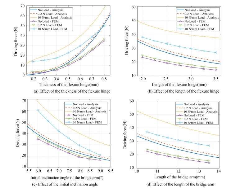
Fig. 9 depicts the driving force corresponding to various geometric parameters of a bridge arm under different loads. The driving force was positively relevant to the stiffness (the inverse of the compliance) of the flexure hinges, which decreased with the increase in the length of the bridge arm and the increase in the initial inclination angle of the bridge arm. The increase in the initial inclination angle resulted in the increase in the loading capacity and the decrease in the input stiffness.
|
Fig.9 Driving force subject to geometric parameters |
3 Flexible Mechanism with Two-Stage Linkages
In this section, the developed modeling method is employed to realize the optimization of a flexible mechanism with respect to the maximum displacement amplification ratio. The flexible mechanism was integrated with a two-stage flexure-based linkage, which is a core component of a miniature suction cup as an adhesive mechanism for a micro climbing robot.
Fig. 10 shows the schematic of the proposed suction cup that comprises three piezo actuators, four flexible mechanisms, a polyethylene terephthalate film, and a substrate. Fig. 10(c) presents a bridge-type mechanism with three arms, which produces a normal output driven by a radial input. The input displacement provided by the piezo actuators is radial in parallel.

|
Fig.10 Schematic of the developed micro sucker |
As shown in Fig. 10(d), the substrate integrates a valveless micropump with two planar tapered tubes. The inlet of the micropump is connected to the suction cup and the outlet is exposed to the air. The PET film was used as the micropump film covering on the substrate.
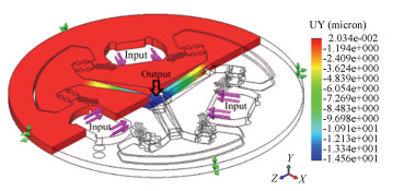
The proposed sucker utilizes the pump of the micropump to generate the negative pressure as the adsorption. Effectively, the air was gradually pumped from the suction cup. In terms of the working principle of the valveless micropump, the flow of the air was realized due to the vibration of the film and the rectification of the tapered tubes. A flexible actuator, which is composed of four flexure mechanisms in lamina, is needed to provide the normal displacement for the film, as shown in Fig. 11. Furthermore, maximizing the output displacement of the flexible mechanism can lead to the optimization of the performance of the proposed sucker[22].
|
Fig.11 Deformation of the flexible mechanism |
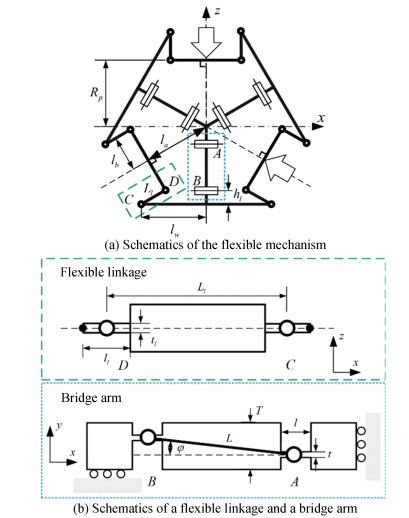
The kinematic model of the flexible mechanism is shown in Fig. 12. As for the developed paralleled mechanism, the asymmetric inputs possibly led to the radial parasitic motion, and a solution is presented in our early work[23]. Due to the symmetry, when the input displacements are identical, the model can be further simplified into one sixth model, which is a combination of a bridge arm and a flexible linkage in series. In the proposed flexible mechanism, the included angle β is identical to π/3, and φ is 0.
|
Fig.12 Kinematic model of the flexible mechanism |
The micropump film is equivalent to an elastic load applied at the flexible mechanism. Based on the above derivations, the output displacement of the flexible mechanism is formulated as
| $ \Delta y^{\mathrm{e}}=\frac{2 a_{21} C_{\theta-M}^{l} L_{l}^{2}}{\left[a_{11}-k_{f}\left(a_{11} b_{22}-a_{12} a_{21}\right)\right]\left(C_{\theta-M}^{l} L_{l}^{2}+4 \sqrt{3} C_{x-F}^{l}\right)+4 \sqrt{3}\left(1-a_{22} k_{f}\right) C_{x-F}^{l} C_{\theta-M}^{l} L_{l}^{2}} \Delta x $ | (26) |
where Cx-Fl and Cθ-Ml denote the compliance components of the flexure hinges in the flexible linkage, Ll denotes the length of the flexible linkage, and kf denotes the effective stiffness of the micropump film.
The golden section method was used to search the optimal parameters within the given ranges to achieve the maximum displacement amplification ratio, and the optimization is summarized as follows:
1) Objective: Maximize the displacement amplification ratio of the flexible mechanism under a 0.01 N load and a 0.6 N/mm stiffness, which is close to the virtual load.
2) Parameters are L, φ, Ll, φl, tl, bl, t, l, B, and b, where B is the width of the flexure hinges in the flexible linkages, and b is the width of the flexure hinges in the bridge arms.
3) Subject to:
a) Stress constrain: σmax < |σ|/na, where na=3 is safety factor.
b) Parameter constrains: 0 < L < 4 mm, 0 < Ll < 4 mm, 0 < t < 0.5 mm; Ll,
With the initial values
| $ \begin{aligned} &{\left[\begin{array}{llllllll} L & \varphi & L_{l} & \varphi_{l} & t & l & B & b \end{array}\right]=} \\ &\ \ \ \ {\left[\begin{array}{llllllll} 3.5 \mathrm{~mm} &5^{\circ}& 3 \mathrm{~mm}& 5^{\circ} & 0.5 \mathrm{~mm} & 0.1 \mathrm{~mm} &0.5 \mathrm{~mm}& 0.5 \mathrm{~mm}\end{array}\right]} \end{aligned} $ |
The optimization results were obtained and adjusted according to the processing technology, as presented in Table 2.
| Table 2 Geometrics of the flexible mechanism |
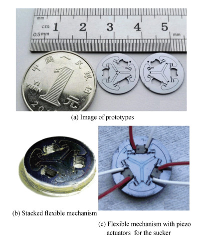
The prototype was fabricated using the deep silicon etching. As shown in Fig. 13, it has a compact size of a diameter of 15 mm and a thickness of 0.5 mm. A post-processing, the surface deposition of SiO2 layer, was conducted to strengthen the surface quality and perform with the electric insulation from the piezo actuators (NAC2001-A01, Noliac, Denmark). The driving voltages of these piezo actuators are required to be positive.
|
Fig.13 Prototype of flexible mechanism |
A high-resolution laser sensor (LSR-HS-PRO-OO4 AcA Corp.) was employed to measure the normal output of the flexible mechanism. The piezo actuators were performed with a stroke of 2.6 μm corresponding to the maximum voltage of 60 V. Because of the excellent linearity characteristics, the input displacement provided by the piezo actuator was assumed to be linear to the driving voltage. Fig. 14 depicts the output displacement subject to various voltages through analytical and experimental investigations. According to the experimental results, the amplification ratio of the flexible mechanism performed non-linearly and the average was 6.56. The FEM simulation indicated that the ratio was 7.46 and the analytical result was 9.15 on the basis of Eq.(26).

|
Fig.14 Deformation of the flexible actuator subject to various driving voltages |
Furthermore, a prototype of the flexible actuator was integrated with a substrate in lamination by using epoxy glue. In the substrate, the micropump chamber is 8 mm in diameter and 80 μm in depth. The plane-tapered tube has an axial length of 2.3 mm, an expanding angle of 10°, and the thickest width of 0.2 mm. In addition, the suction chamber has a 13 mm diameter and a 100 μm depth.
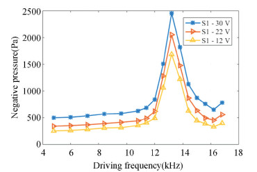
The adsorption of the proposed sucker was measured by a negative pressure sensor (K409-005VUSBH, Omega, USA). A power amplifier board was developed to supply the positive alternating voltage. The negative pressure subject to various driving frequencies is shown in Fig. 15. The maximum negative pressure in the suction cup was up to 2.45 kPa when the driving frequency arrived at the natural frequency of 13.2 kHz. The voltages, as shown in the legend of Fig. 15, indicated the peak-to-peak voltage, which was measured using an oscilloscope (Tektronix TDS 2024C).
|
Fig.15 Negative pressure of the suction cup |
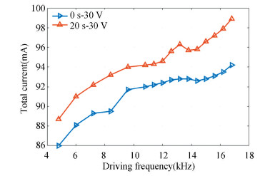
A universal meter was used to measure the total current from a 60 V DC power source. Fig. 16 depicts the total current subject to various driving frequencies and the peak-to-peak driving voltage of 30 V, where the blue curve denotes the starting currents, and the orange curve denotes the current in 20 seconds. The charge quantity remained identical during the charging and discharging process. Therefore, the total current increased with the driving frequency. Due to the thermal loss of the piezo actuators and the resistor in the discharge circuit, the total current increased with the work time. The total power consumption was up to 6 W in 20 seconds when the sucker realized the maximum adsorption at the driving frequency of 13.2.
|
Fig.16 Total current at various driving frequencies |
4 Discussion
The calculation error of the analytical results was higher than that of the FEM results because the deformations of the rigid bodies were ignored in the proposed elastic model. In terms of Euler-Bernoulli beam theorem, the shearing at the flexure hinges was ignored, which further caused the calculation error. The external load resulted in the increase in the shearing in flexure hinges and the calculation error of the developed model. According to Figs. 8-9, the bridge arm produced the output displacement of 180 μm subject to a load of 10 N/mm, which was equal to a load of 1.8 N. The deviation between the analytical model and the FEM subject to a load of 10 N/mm was larger than that subject to a load of 0.2 N. In contrast, the proposed elastic modeling method was proved valid to qualitatively evaluate the kinematic performances of the flexure-based linkage under external loads and the effects of the material properties and geometric parameters. Hence, the proposed modeling method is sufficient to optimize a flexible mechanism that is composed of flexible linkage.
The following conclusions are addressed regarding the effects of materials, external loads, and geometric parameters:
1) The displacement amplification ratio of a flexure-based linkage is affected by the material properties, especially under a load.
2) The bending compliance of the flexure hinges is beneficial for the kinematic performances in displacement amplification, input stiffness, and work efficiency. However, it also leads to the decrease of the mechanical stiffness and strength (the load capacity), which causes the sharp decrease in the displacement amplification ratio subject to the action of an external load.
3) The initial inclination angle of the flexible linkage will enhance the mechanical stiffness, but affect the input stiffness. Therefore, the displacement amplification ratio and driving force will decrease as the initial inclination angle increase.
5 ConclusionsAn elastic modeling method was proposed to simplify the investigation on the kinematic performances of a flexible linkage under motion constrains and external loads. The elastic model developed herein is convenient to optimize the configuration of a flexible actuator with two-stage flexible linkages for the micro suction cup of a micro climbing robot. The optimized flexible mechanism had the displacement amplification ratio of 6.56 in the experimental investigation, which helped a miniature micropump sucker to achieve a maximum negative pressure of 2.45 kPa.
AppendixThe calculation factors in Eqs. (18)-(25) are as follows:
| $ a_{11}=2 C_{x-F}+\frac{1}{2} C_{\theta-M} L^{2} \sin ^{2} \varphi $ | (A-1) |
| $ a_{12}= C_{y-M} L \sin \varphi+\frac{1}{2} C_{\theta-M} L^{2} \sin \varphi \cos \varphi $ | (A-2) |
| $ a_{21}=\left[\frac{1}{2}(l+L \cos \varphi) C_{\theta-M}+C_{y-M}\right] L \sin \varphi $ | (A-3) |
| $ \begin{aligned} a_{22}= &2 C_{y-F}+(l+L \cos \varphi)\left(C_{y-M}-\frac{1}{2} C_{\theta-M} L \cos \varphi\right)+\\ &C_{y-M} L \cos \varphi \end{aligned} $ | (A-4) |
| [1] |
Bhagat U, Shirinzadeh B, Clark L, et al. Design and analysis of a novel flexure-based 3-DOF mechanism. Mechanism and Machine Theory, 2014, 74: 173-187. DOI:10.1016/j.mechmachtheory.2013.12.006 (  0) 0) |
| [2] |
Wang R, Zhang X. A planar 3-DOF nanopositioning platform with large magnification. Precision Engineering, 2016, 46: 221-231. DOI:10.1016/j.precisioneng.2016.04.016 (  0) 0) |
| [3] |
Guo J, Chee S K, Yano T, et al. Micro-vibration stage using piezo actuators. Sensors and Actuators A: Physical, 2013, 194: 119-127. DOI:10.1016/j.sna.2013.01.025 (  0) 0) |
| [4] |
Ling M, Cao J, Jiang Z, et al. Modular kinematics and statics modeling for precision positioning stage. Mechanism and Machine Theory, 2017, 107: 274-282. DOI:10.1016/j.mechmachtheory.2016.10.009 (  0) 0) |
| [5] |
Smith S T, Badami V G, Dale J S, et al. Elliptical flexure hinges. Review of Scientific Instruments, 1997, 68(3): 1474-1483. DOI:10.1063/1.1147635 (  0) 0) |
| [6] |
Lobontiu N, Paine J S N, Garcia E, et al. Corner-filleted flexure hinges. Journal of Mechanical Design, 2001, 123(3): 346-352. DOI:10.1115/1.1372190 (  0) 0) |
| [7] |
Dong W, Chen F, Gao F, et al. Development and analysis of a bridge-lever-type displacement amplifier based on hybrid flexure hinges. Precision Engineering, 2018, 54: 171-181. DOI:10.1016/j.precisioneng.2018.04.017 (  0) 0) |
| [8] |
Qin Y, Shirinzadeh B, Zhang D, et al. Design and kinematics modeling of a novel 3-DOF monolithic manipulator featuring improved Scott-Russell mechanisms. Journal of Mechanical Design, 2013, 135(10): 101004-101012. DOI:10.1115/1.4024979 (  0) 0) |
| [9] |
Tang H, Li Y. A new flexure-based Yθ nanomanipulator with nanometer-scale resolution and millimeter-scale workspace. IEEE/ASME Transactions on Mechatronics, 2015, 20(3): 1320-1330. DOI:10.1109/TMECH.2014.2342752 (  0) 0) |
| [10] |
Choi K-B, Lee J J, Hata S. A piezo-driven compliant stage with double mechanical amplification mechanisms arranged in parallel. Sensors and Actuators A: Physical, 2010, 161(1-2): 173-181. DOI:10.1016/j.sna.2010.05.027 (  0) 0) |
| [11] |
Wang F, Liang C, Tian Y, et al. Design of a piezoelectric-actuated microgripper with a three-stage flexure-based amplification. IEEE/ASME Transactions on Mechatronics, 2015, 20(5): 2205-2213. DOI:10.1109/tmech.2014.2368789 (  0) 0) |
| [12] |
Sun X, Chen W, Fatikow S, et al. A novel piezo-driven microgripper with a large jaw displacement. Microsystem Technologies, 2015, 21(4): 931-942. DOI:10.1007/s00542-014-2199-3 (  0) 0) |
| [13] |
Wang F, Liang C, Tian Y, et al. Design and control of a compliant microgripper with a large amplification ratio for high-speed micro manipulation. IEEE/ASME Transactions on Mechatronics, 2016, 21(3): 1262-1271. DOI:10.1109/tmech.2016.2523564 (  0) 0) |
| [14] |
Chen W, Lu Q, Kong C, et al. Design, analysis and validation of the bridge-type displacement amplification mechanism with circular-axis leaf-type flexure hinges for micro-grasping system. Microsystem Technologies, 2019, 25(3): 1121-1128. DOI:10.1007/s00542-018-4064-2 (  0) 0) |
| [15] |
Choi K-B, Lee J J, Kim G H, et al. Amplification ratio analysis of a bridge-type mechanical amplification mechanism based on a fully compliant model. Mechanism and Machine Theory, 2018, 121: 355-372. DOI:10.1016/j.mechmachtheory.2017.11.002 (  0) 0) |
| [16] |
Sun X, Chen W, Tian Y, et al. A novel flexure-based microgripper with double amplification mechanisms for micro/nano manipulation. Review of Scientific Instruments, 2013, 84(8): 085002. DOI:10.1063/1.4817695 (  0) 0) |
| [17] |
Luo Y, Liu W, Wu L. Analysis of the displacement of lumped compliant parallel-guiding mechanism considering parasitic rotation and deflection on the guiding plate and rigid beams. Mechanism and Machine Theory, 2015, 91: 50-68. DOI:10.1016/j.mechmachtheory.2015.04.007 (  0) 0) |
| [18] |
Mo C, Wright R, Slaughter W S, et al. Behaviour of a unimorph circular piezoelectric actuator. Smart Materials and Structures, 2006, 15(4): 1094-1102. DOI:10.1088/0964-1726/15/4/023 (  0) 0) |
| [19] |
Wang D H, Huo J. Modeling and testing of the static deflections of circular piezoelectric unimorph actuators. Journal of Intelligent Material Systems and Structures, 2010, 21(16): 1603-1616. DOI:10.1177/1045389x10385485 (  0) 0) |
| [20] |
Qi K-Q, Xiang Y, Fang C, et al. Analysis of the displacement amplification ratio of bridge-type mechanism. Mechanism and Machine Theory, 2015, 87: 45-56. DOI:10.1016/j.mechmachtheory.2014.12.013 (  0) 0) |
| [21] |
Zhu W-L, Zhu Z, Shi Y, et al. Design, modeling, analysis and testing of a novel piezo-actuated XY compliant mechanism for large workspace nano-positioning. Smart Materials and Structures, 2016, 25(11): 115033. DOI:10.1088/0964-1726/25/11/115033 (  0) 0) |
| [22] |
Liu J, Yan W, Zhao Y. A micropump sucker using a piezo-driven flexible mechanism. Journal of Mechanisms and Robotics, 2019, 11(4): 041009-041022. DOI:10.1115/1.4043600 (  0) 0) |
| [23] |
Liu J, Guan E, Li P, et al. Deflection behavior of a piezo-driven flexible actuator for vacuum micropumps. Sensors and Actuators A: Physical, 2017, 267: 30-41. DOI:10.1016/j.sna.2017.09.029 (  0) 0) |
 2021, Vol. 28


