2. National Key Laboratory of Science and Technology on Advanced Composites in Special Environments, Harbin Institute of Technology, Harbin 150080, China;
3. Shenyang Aircraft Design and Research Institute, Aviation Industry Corporation of China, Shenyang 110000, China;
4. School of Aeronautics and Astronautics, Harbin Institute of Technology, Harbin 150001, China
In recent years, ceramic matrix composites (CMC) have received considerable attention for propulsion system and vehicle hot structure applications, because of their prominent advantages in thermo-mechanical properties and chemical stability at elevated temperatures[1-4]. The potential application of CMC in aircrafts arises vast majorities of connections with various structures, by mechanical or adhesive techniques. As the weakest structural element, joint structure design is of paramount importance in maintaining structural safety of the aircraft structure. However, for bolted joint, the mechanical performances of joints have been significantly affected by various factors, such as fastener types, geometric configurations, and assembly states. In previous design practices of bolted joints, the effects of assembly factors on mechanical performance have been investigated by experimental and numerical methods[5-14]. In contrast to the carbon-fiber/polymer composite counterparts, research on failure behaviors of CMC joint structures were relatively limited[15-18]. Li et al.[17] carried out experimental and numerical work on the damage mode and fracture load of C/SiC joints. The influences of geometric configurations on the mechanical properties of C/SiC joints with pins or bolts were studied. Zhao et al.[18] evaluated the most suitable damage models by comparing failure analyses results with experimental data of open-hole C/SiC composite laminates. Then they used the progressive failure model to simulate failure process of a three-bolt C/SiC composite joint. In our previous studies, the thermal mismatch effect and bolt design of a hybrid CMC/superalloy joint was discussed based on damage mechanical analysis[19-20]. To fully exploit structural efficiency of joint, attention of this work was paid to the effect studies of assembly parameters on the tensile behavior of CMC bolted joints. A non-linear progressive damage analysis was carried out to predict tensile behavior and failure modes of a hybrid CMC/superalloy joint. The influences of fastener's preload and bolt-hole clearance on mechanical behaviors of the bolted joint were examined. The associated damage modes and failure mechanisms for the studied joint will be provided for further discussion.
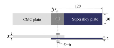
1 Finite Element Modeling of Hybrid CMC/Superalloy Bolted JointA 2D plain-woven C/SiC composite plate and GH4169 alloy plate were assembled together using a bolt made of GH4141 alloy, as shown in Fig. 1. The tensile process of the hybrid single-bolt, single-lap joint C/SiC composite, and superalloy bolted joint was simulated via Abaqus/standard software. The finite element model of the joint structure, as illustrated in Ref. [20], was discretized by using C3D8R elements with hourglass control. The assigned mechanical properties of GH4169 and GH4141 alloy have been given in Refs. [19-20]. Five contact pairs were defined for the joint structure, i.e., the fastener shank to the hole of ceramic composite plate or the hole of superalloy plate, the fastener head or nut to the outer surfaces of the two plates, and the faying surface of two plates. Classic friction coefficient of 0.30 was assigned to all contacted surfaces. Bolt-hole clearance levels were set by giving interference fit values of the fastener shank contact pairs. Bolt load function in ABAQUS was utilized to apply preload to all the considered joints. All three translational directions (Ux, Uy, and Uz) of the right end of superalloy plate was fixed. Two translational directions (Uy and Uz) and three rotational directions (Rx, Ry and Rz) of the left end of the composite plate was fixed, and prescribed displacements were quasi-statically applied along Ux direction.
|
Fig.1 Specimen geometry configuration of 2D C/SiC composite-superalloy bolt joint structure (all dimensions in mm) |
2 Progressive Damage Analysis Method 2.1 Constituent Model for 2D C/SiC Composites
To simulate damage behavior of 2D plain-woven C/SiC composite, a macroscopic constituent model by Li et al.[21] was utilized to address the nonlinear stress-strain relationship of 2D C/SiC composites. According to their model, the tensile and shear loading-unloading stress-strain curves were fitted and differentiated to the detectable strain, and the tangent modulus is obtained as[21]
| $ \begin{gathered} E_{i}^{\mathrm{tan}}=\frac{\mathrm{d} \sigma_{i}}{\mathrm{~d} \varepsilon_{i}}=A_{1}+2 A_{2} \varepsilon_{i}+3 A_{3} \varepsilon_{i}^{2}+4 A_{4} \varepsilon_{i}^{3}+ \\ 5 A_{5} \varepsilon_{i}^{4} \quad\left(0 \leqslant \varepsilon_{i} \leqslant \varepsilon_{i}^{f}, i=1, 2\right) \end{gathered} $ | (1) |
| $ \begin{gathered} G_{12}^{\mathrm{tan}}=\frac{\mathrm{d} \tau_{12}}{\mathrm{~d} \gamma_{12}}=B_{1}+2 B_{2} \gamma_{12}+3 B_{3} \gamma_{12}^{2}+ \\ 4 B_{4} \gamma_{12}^{3}+5 B_{5} \gamma_{12}^{4}\left(\left|\gamma_{12}\right| \leqslant \gamma_{12}^{f}\right) \end{gathered} $ | (2) |
where εif is the tensile fracture strain in principle direction 1 and 2, repectively. γ12f is the shear fracture strain in the 1-2 plane. Aj and Bj (j=1, 2, ..5) are the fitted coefficients. When the strain εi and γ12 equal zero, the Eitan and G12tan are the initial elastic and shear modulus of the 2D C/SiC composite.
Under unloading or reloading processes, the elastic modulus E1u and shear modulus G12u can be fitted by a logical function with the associated strain as given[21]:
| $ E_{i}^{u}=A_{6}+\frac{A_{7}-A_{6}}{1+\left(\varepsilon_{i}^{m} / x_{0}\right)^{p_{0}}}\left(\varepsilon_{i} \leqslant \varepsilon_{i}^{m}, i=1, 2\right) $ | (3) |
| $ G_{12}^{u}=B_{6}+\frac{B_{7}-B_{6}}{1+\left(\left|\gamma_{12}^{m}\right| / x_{1}\right)^{p_{1}}}\left(\left|\gamma_{12}\right| \leqslant\left|\gamma_{12}^{m}\right|\right) $ | (4) |
where A6, A7, p0, x0, and B6, B7, p1 and x1 are the shape parameters of each logical function, respectively. The experimental tensile and shear stress-strain curves and other mechanical properties of the C/SiC composite material were provided in Refs. [19-20].
2.2 Failure CriterionTsai-Wu criterion is utilized here to justify the occurrence of relevant failure modes, and is described by the formula[22]:
| $ \begin{array}{r} F_{11} \sigma_{1}^{2}+F_{22} \sigma_{2}^{2}+F_{33} \sigma_{3}^{2}+F_{44} \tau_{12}^{2}+F_{55} \tau_{13}^{2}+ \\ F_{66} \tau_{23}^{2}+2 F_{12} \sigma_{1} \sigma_{2}+2 F_{13} \sigma_{1} \sigma_{3}+2 F_{23} \sigma_{2} \sigma_{3}+ \\ F_{1} \sigma_{1}+F_{2} \sigma_{2}+F_{3} \sigma_{3} \geqslant 1 \end{array} $ | (5) |
where Fij and Fi are determined as follows:
| $ \begin{gathered} F_{1}=\frac{1}{X_{t}}-\frac{1}{\left|X_{c}\right|}, F_{2}=\frac{1}{Y_{t}}-\frac{1}{\left|Y_{c}\right|}, F_{3}=\frac{1}{Z_{t}}-\frac{1}{\left|Z_{c}\right|} \\ F_{11}=\frac{1}{X_{t}\left|X_{c}\right|}, F_{22}=\frac{1}{Y_{t}\left|Y_{c}\right|}, F_{33}=\frac{1}{Z_{t}\left|Z_{c}\right|} \\ F_{44}=\frac{1}{S_{12}^{2}}, F_{55}=\frac{1}{S_{13}^{2}}, F_{66}=\frac{1}{S_{23}^{2}} \\ F_{12}=-\frac{1}{2 \sqrt{X_{t} X_{c} Y_{t} Y_{c}}}, F_{23}=-\frac{1}{2 \sqrt{Y_{t} Y_{c} Z_{t} Z_{c}}} \\ F_{13}=-\frac{1}{2 \sqrt{X_{t} X_{c} Z_{t} Z_{c}}} \end{gathered} $ | (6) |
where σ1, σ2, and σ3 are the normal stresses in the directions 1, 2, and 3, respectively; τ12, τ13, and τ23 are the shear stress in the 1-2 plane, 1-3 plane, and 2-3 plane, respectively.
2.3 Material Degradation RuleIf the material failure occurred, the most commonly-used method is to reduce the stiffness of the "failed" elements, and then redistribute the load with nearby elements while maintaining global equilibrium. To prevent numerical convergence problems, the associated material stiffness would be reduced to 1% of its undamaged value.
2.4 Validation of the Progressive Damage ModelFor validation of the proposed method, a uniaxial tensile loading of an open-hole 2D woven C/SiC composite laminate was simulated by using the geometric configuration and test conditions of composite samples given in Ref. [21]. Details about the validation of the simulated stress-strain curves of 2D-woven C/SiC composite open-hole plate have been given in Ref.[20]. The simulated mechanical behavior and failure mode for the 2D plain-woven CMC open-hole laminate agree well with the experimental results[21].
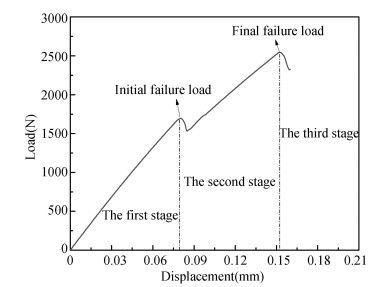
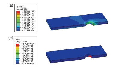
3 Parametric Studies 3.1 Typical Tensile Behavior of the Studied Hybrid Bolted JointA typical load-displacement curve for the hybrid joint with neat-fit and zero preload is shown in Fig. 2. The curve can be differentiated by three stages. For the first stage with the imposed displacement below about 0.08 mm, the load and displacement correspond to a linear characteristic, and its slope reflects the initial stiffness of the joint structure. At the second stage, the damage is initiated in the elements around the hole-edge area, as shown in the obtained equivalent stress contour map and failure element contour map for the composite when the applied displacement is 0.08 mm in Fig. 3. With the increase of displacement, the bearing load firstly decreases and then increases. The curve displays another approximate linear stage but with lower slope. The damage keeps on propagating as the load increases.
|
Fig.2 Typical load-displacement curve for the C/SiC composite and superalloy hybrid bolted joint |
|
Fig.3 Equivalent stress contour map (a) and failure element contour map (b) of C/SiC composite plate at 0.08 mm tensile displacement |
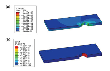
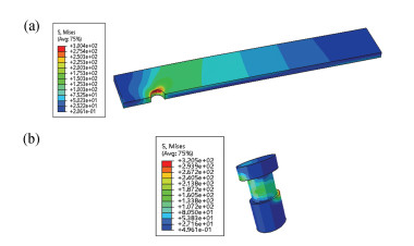
The joint maintains an upward trend in load-bearing capacity. At the third stage, a sharp drop in the bearing load can be observed in the load-displacement curve of the joint when the tensile displacement is larger than 0.15 mm. It means that the joint loses load-bearing capability due to large areas of damage in the composite, as illustrated from the equivalent stress contour map and failure element contour map for the composite when the applied displacement is 0.15 mm in Fig. 4. The corresponding stress contour maps for the superalloy plate and bolt at this displacement are shown in Fig. 5. The maximum values of equivalent stress for the superalloy plate and bolt are 300.00 MPa and 320.50 MPa, respectively, much less than their respective nominal yield stress, i.e., 1040 MPa for GH4169 alloy and 1070 MPa for GH4141 alloy. Therefore, the assumption of elastic behavior for the superalloy plate and bolt is reasonable in the tensile simulation of the joint.
|
Fig.4 Equivalent stress contour map (a) and failure element contour map (b) of C/SiC composite plate at 0.15 mm tensile displacement |
|
Fig.5 Equivalent stress contour maps of superalloy plate (a) and bolt (b) at 0.15 mm tensile displacement |
3.2 Effect of Bolt Preload
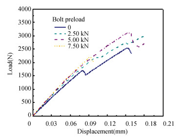
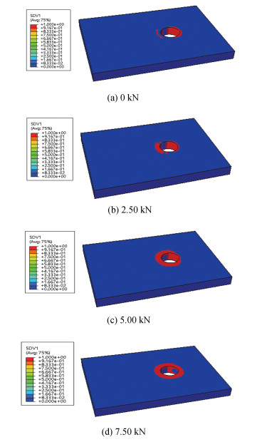
A parametric study was conducted to analyze the influence of joint parameters on the tensile behaviors of the bolted joint. The load-displacements curves for different values of bolt preload are shown in Fig. 6. The joint stiffness and strength values are listed in Table 1 and Table 2, respectively. When the imposed bolt preload achieves 7.50 kN, only the first stage stiffness and final failure load can be observed in the load-displacement curve. The results show that the application of bolt preload from 0 kN to 7.50 kN leads to a minor increase in the first stage stiffness from 21.39 kN/mm to 25.55 kN/mm, whilst the second stage stiffness drops first from 15.06 kN/mm for the non-preload case to 13.74 kN/mm for 2.50 kN/mm preload and then rises to 15.37 kN/mm for 5.00 kN/mm preload. The loss of stiffness of the two stages is around 30%-40% for the considered cases. The final failure load rises first and then declines with the rise of bolt preload, and the maximum value of 3.12 kN is achieved when the bolt preload is 5.00 kN, indicating an optimum value of the joint structure bolt load exists. As shown in Fig. 7, the final failure areas around the fastener hole for the hybrid bolted joint is enlarged with rising of bolt preload value.
|
Fig.6 Load-displacement curves for the hybrid bolted joint under various bolt preloads |
| Table 1 The joint stiffness as a function of bolt preload for the hybrid bolted joints |
| Table 2 The failure loads as function of bolt preload for the hybrid bolted joints |
|
Fig.7 The final failure areas for the hybrid bolted joint under different preload levels |
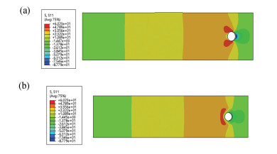
Such changes in the joint performance can be attributed to the following reasons. With the rise of the clamping force through the thickness direction of the joint, the contact friction force between the two plates shares more proportions of the external tensile load. Under the same loading level, the raised friction force effectively inhibits the stress augmentation around the hole-edge area, thus improving the joint strength. This can be revealed by the simulated axial stress contour map of the composite plate. The results for the joint structure at 1.00 kN tensile load, as shown in Fig. 8, clearly demonstrate that the extent of compression area and the maximum value of compressive stress for 5.00 kN bolt preload are dramatically reduced in comparison with 0 kN preload case. Furthermore, the clamping force provides "lateral support" for the joint area, diminishing the secondary bending. Therefore, the first stage stiffness in the load-displacement curve increases, as listed in Table 1. However, the gain effect in mechanical performance is conditional.
|
Fig.8 Axial stress contour maps of the composite plate for 0 kN bolt preload (a) and 5.00 kN bolt preload when the joint structures are applied 1.00 kN tensile load |
When the applied preload is growing to a certain value, excessive clamping may crush the hole-edge elements of the composite plate before it bears the tensile load, leading to the loss of joint performance for 7.50 kN bolt preload. Appropriate preload can increase the load-carrying capacity of the joints by limiting the extension of failure around the fastener holes. These findings are in accordance with the conclusions provided by Liu et al.[14] and Chishti et al.[12-13] for bolted joints.
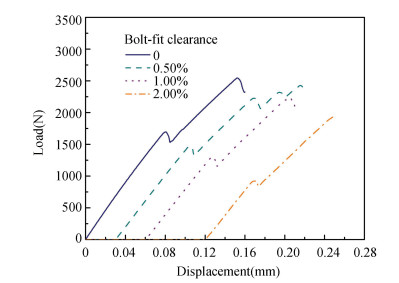
3.3 Effect of Bolt-Hole ClearanceThe load-displacement responses of the joint with varying bolt-hole clearance are shown in Fig. 9. The variations of stiffness and strength of the hybrid single-lap joint with the applied bolt-hole clearance are shown in Table 3 and Table 4, respectively. The results in Table 3 demonstrate that the introduction of 0-2.00% bolt-hole clearance leads to a slight decline in the first stage stiffness, whereas no significant changes in the second stage stiffness of the bolted joint. Compared with the first stage stiffness, there are 23.86%-29.59% reduction in the second stage stiffness for the studied clearance levels.
|
Fig.9 Load-displacement relationship for the hybrid bolted joint under different bolt-hole clearances |
| Table 3 Joint stiffness as a function of bolt-fit clearance for the hybrid bolted joints |
| Table 4 The failure loads as function of bolt-fit clearance for the hybrid bolted joints |
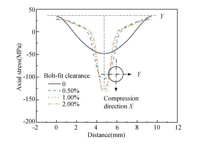
From Table 4, the initial and final failure loads drop from 1.70 kN to 0.92 kN and from 2.54 kN to 1.93 kN, respectively, accounting for 45.88% and 24.02% loss in their values for 2.00% clearance joint relative to the neat-fit case. It is reported that prediction of joint strength could be significantly affected by clearance levels for single-bolt or pin-loaded joints[5, 7, 8-9, 23-25]. The increase in the bolt hole clearance generates smaller areas in transferring tensile loads, which increases stress concentrations around the hole edge. This can be clearly shown from the changes of axial stress distribution of composite plate hole under various levels of clearance. As shown in Fig. 10, when 0.50 kN tensile load is applied to the joint structures, 1.00% oversize of bolt-hole clearance from neat-fit brings about compressive stress increase of the central area by almost three times. However, when continue enlarging the clearance to 2.00%, the increase in the axial stresses is not significant.
|
Fig.10 Axial compressive stress of hole edge on the composite plate under various levels of bolt clearance when applying 0.50 kN tensile load to the joint structures |
4 Conclusions
In the present work, a parametric study was carried out to illustrate the effects of bolt preload and bolt-hole clearance on mechanical behaviors for the 2D C/SiC composite and superalloy hybrid bolted joint by progressive failure analysis. It was found that appropriate bolt preload increased the friction force between two plates of the joint, which inhibited stress augmentation around the fastener hole, thus improving joint strength. The optimum value of bolt preload resulted in 56.47% and 22.83% respective increase in the initial and final failure load for the bolted joint in comparison with the case with zero preload. The initial and final failure load respectively dropped by 45.88% and 24.02% for the joint with 2.00% bolt-hole clearance relative to the neat-fit case, respectively. The loss in failure loads can be reduced to the stress concentration around the hole-edge area by the introduction of increased bolt-hole clearance. The present work provides valuable design method for promoting application of ceramic matrix composite joints in aircrafts.
| [1] |
Naslain R. Preparation and properties of non-oxide CMCs for application in engines and nuclear reactors: an overview. Composites Science and Technology, 2004, 64(2): 155-157. DOI:10.1016/S0266-3538(03)00230-6 (  0) 0) |
| [2] |
Hald H, Hansel D, Ruhle F, et al. Development of a Joining Method for High Temperature Constructions. European Conference on Spacecraft Structures, Materials and Mechanical Testing, Braunschweig/Germany. Paris: European Space Agency (ESA), ESA-SP. 333.
(  0) 0) |
| [3] |
Dogigli M, Handrick K, Bickel M, et al. CMC Key Technologies-Background, Status, Present and Future Applications. http://adsabs.harvard.edu/pdf/2003ESASP.521...79D, 2021-03-23.
(  0) 0) |
| [4] |
Bohrk H, Beyermann U. Secure tightening of a CMC fastener for the heat shield of re-entry vehicles. Composite Structures, 2014, 92(1): 107-112. DOI:10.1016/j.compstruct.2009.07.002 (  0) 0) |
| [5] |
McCarthy C T, McCarthy M A. Three-dimensional finite element analysis of single-bolt, single-lap composite bolted joints: Part Ⅱ-effects of bolt-hole clearance. Composite Structures, 2005, 71(2): 159-175. DOI:10.1016/j.compstruct.2004.09.023 (  0) 0) |
| [6] |
McCarthy M A, McCarthy C T, Lawlor V P, et al. Three-dimensional finite element analysis of single-bolt, single-lap composite bolted joints: part I〞model development and validation. Composite Structures, 2005, 71(2): 140-158. DOI:10.1016/j.compstruct.2004.09.024 (  0) 0) |
| [7] |
McCarthy M A, Lawlor V P, Stanley W F, et al. Bolt-hole clearance effects and strength criteria in single-bolt, single-lap, composite bolted joints. Composites Science and Technology, 2002, 62(11): 1415-1431. DOI:10.1016/S0266-3538(02)00088-X (  0) 0) |
| [8] |
McCarthy C T, McCarthy M A, Lawlor V P. Progressive damage analysis of multi-bolt composite joints with variable bolt-hole clearances. Composites: Part B, 2005, 36(4): 290-305. DOI:10.1016/j.compositesb.2004.11.003 (  0) 0) |
| [9] |
Egan B, McCarthy C T, McCarthy M A, et al. Stress analysis of single-bolt, single-lap, countersunk composite joints with variable bolt-hole clearance. Composite Structures, 2012, 94(3): 1038-1051. DOI:10.1016/j.compstruct.2011.10.004 (  0) 0) |
| [10] |
Qin T L, Zhao L B, Zhang J Y. Fastener effects on mechanical behaviors of double-lap composite joints. Composite Structures, 2013, 100: 413-423. DOI:10.1016/j.compstruct.2013.01.008 (  0) 0) |
| [11] |
Olmedo A, Santiuste C, Barbero E. An analytical model for the secondary bending prediction in single-lap composite bolted-joints. Composite Structures, 2014, 111: 354-361. DOI:10.1016/j.compstruct.2014.01.015 (  0) 0) |
| [12] |
Chishti M, Wang C H, Thomson R S, et al. Numerical analysis of damage progression and strength of countersunk composite joints. Composite Structures, 2012, 94(2): 643-653. DOI:10.1016/j.compstruct.2011.08.030 (  0) 0) |
| [13] |
Chishti M, Wang C H, Thomson R S, et al. Experimental investigation of damage progression and strength of countersunk composite joints. Composite Structures, 2012, 94(3): 865-873. DOI:10.1016/j.compstruct.2011.10.011 (  0) 0) |
| [14] |
Liu L Q, Zhang J Q, Chen K K, et al. Combined and interactive effects of interference fit and preloads on composite joints. Chinese Journal of Aeronautics, 2014, 27(3): 716-729. DOI:10.1016/j.cja.2014.04.014 (  0) 0) |
| [15] |
Yang C P, Jiao G Q, Wang B, et al. Damage-based failure theory and its application to 2D-C/SiC composites. Composites: Part A, 2015, 77: 181-187. (  0) 0) |
| [16] |
Mei H, Cheng L F, Ke Q Q, et al. High-temperature tensile properties and oxidation behavior of carbon fiber reinforced silicon carbide bolts in a simulated re-entry environment. Carbon, 2010, 48(11): 3007-3013. DOI:10.1016/j.carbon.2010.01.056 (  0) 0) |
| [17] |
Li G D, Wu X F, Zhang C R, et al. Theoretical simulation and experimental verification of C/SiC joints with pins or bolts. Materials and Design, 2014, 53: 1071-1076. DOI:10.1016/j.matdes.2013.08.001 (  0) 0) |
| [18] |
Zhao L B, Yang W, Cao T C, et al. A progressive failure analysis of all-C/SiC composite multi-bolt joints. Composite Structures, 2018, 202: 1059-1068. DOI:10.1016/j.compstruct.2018.05.029 (  0) 0) |
| [19] |
Lü C, Zhao S Y, Li Z Y, et al. Bolt design of ceramic matrix composite and superalloy bolted joint based on damage failure load. Journal of Harbin Institute of Technology (New series), 2021, 28(2): 55-61. DOI:10.11916/j.issn.1005-9113.2019061 (  0) 0) |
| [20] |
Zhao S Y, Dong J L, Lv C, et al. Thermal mismatch effect and high-temperature tensile performance simulation of hybrid CMC and superalloy bolted joint by progressive damage analysis. International Journal of Aerospace Engineering, 2020, 2020: 8739638. DOI:10.1155/2020/8739638 (  0) 0) |
| [21] |
Li J, Jiao G Q, Wang B, et al. A nonlinear damage constitutive model for 2D woven C/SiC composite material and its application. Acta Materiae Compositae Sinica, 2013, 30(1): 165-171. DOI:10.13801/j.cnki.fhclxb.2013.01.034 (  0) 0) |
| [22] |
Tsai S W, Wu E M. A General Theory of Strength for Anisotropic Materials. http://citeseerx.ist.psu.edu/viewdoc/download?doi=10.1.1.1007.174&rep=rep1&type=pdf., 2021-03-18.
(  0) 0) |
| [23] |
Lawlor V P, McCarthy M A, Stanley W F. Experimental study on effects of clearance on single bolt, single shear, composite bolted joints. Plastics, Rubber and Composites, 2002, 31(9): 405-411. DOI:10.1179/146580102225006521 (  0) 0) |
| [24] |
Lawlor V P, McCarthy M A, Stanley W F. An experimental study of bolt-hole clearance effects in double-lap, multi-bolt composite joints. Composite Structures, 2005, 71(2): 176-90. DOI:10.1016/j.compstruct.2004.09.025 (  0) 0) |
| [25] |
Padhi G S, McCarthy M A, Stanley C T. BOLJAT: a tool for designing composite bolted joints using three-dimensional finite element analysis. Composites Part A: Applied Science and Manufacturing, 2002, 33(11): 1573-1584. DOI:10.1016/S1359-835X(02)00113-6 (  0) 0) |
 2021, Vol. 28


