The capability of autonomous underwater vehicles in actively carrying out repetitive and dangerous missions in high-risk and out of reach environments to discover, monitor pipelines and underwater structures, perform maintenance and transportation of goods, and even serve for security and military purposes has attracted the attention of many universities and research centers. Since the 1960s, the use of these robotic tools is already the essentiality of many underwater operations and projects, but they need to be placed in an ideal position and balanced to work in such environment.
Over the past 20 years, guidance, navigation, and control of sea vehicles (ships, surface vessels, and underwater vehicles) have garnered a lot of attention due to the high motivation of their application in the oil industry, scientific discoveries in oceanography, archeology and marine biology research, search and rescue missions, monitoring, and inspection[1]. In the following years, this technology has been suggested for smaller vessels, semi-submersibles, and oil rigs in addition to large ships. Dynamic positioning (DP) systems maintain the position of floating structures in a fixed location or control offshore missions in a pre-determined path with an arbitrary direction receiving support from its own fully actuated thrusters[2]. Some of the dynamic positioning advantages are perfect maneuverability of the vehicle, independency of the positioning from water depth, and prevention from the destruction of the seabed[3]. The first DP system was introduced in the 1960s to move in a horizontal plane[4]. Oil and gas industries produce a series of high-tech equipment, in which DP serves as one of the most modern technologies in control and navigation in maritime applications, playing an effective role particularly for the development of offshore oil and gas installations. Vehicles equipped with DP technology fulfill the possibility of production from oil and gas fields, which are far offshore in deep waters. Therefore, drilling rigs and pipe-laying vessels equipped with this technology have provided the required facilities to extract and transport raw materials from far fields. The increment of intelligence and complexity of DP in surface and underwater vehicles has improved their reliability.
Since the 1990s, DP has been extensively studied as a key technique for underwater vehicles, underwater interventions, and monitoring missions[5].
The pioneers in the field of dynamic positioning are worth noting. In 1961, a drilling ship Cuss I was developed, which is one of the first instances of the ships that benefited from this system. This ship had four rotatable engines installed on four sides of the ship, maintaining its stability against the waves, wind, and other environmental factors. Using this system made the drilling process at a depth of 948 m possible. In the same year, another ship named Eureka was introduced, which used similar control system, but it utilized an automatic system to help the drilling process at a depth of 1300 m under the environmental conditions with 40 knot (21 m/s) winds and 6 m waves. In 1964, the ship Caldrill I was equipped with four engines-which had more power-and two parallel controllers, allowing drilling at a depth of 2000 m with the help of two attached inclinometers to the vessel to maintain its position[4].
In recent years, AUVs with capabilities like high speed, better performance in deep water, lower risk factor as opposed to high risk factor for divers, was used in autonomous underwater vehicles for many underwater missions, making it one of the necessities of maritime industries. Since the 1990s, extensive researches have been done in this regard[6]. The main issue of autonomous underwater vehicles is to maintain their stability in reaching the desired point and sustaining the stability at that point afterward. But due to the complexity of hydrodynamic terms as well as sophisticated dynamics of the vehicle, designing any type of controller will be dependent on its equations which were done in the ships with three degrees of freedom. One of the first researchers which sustained the situation and maintained AUV's orientation was Leonard[7]. The rules of open loop with small amplitude periodic time were used in order to reposition and reorient underactuated AUVs. Then continuous periodic feedback control laws to asymptotically stabilize an underactuated AUV were used by Pettersen and Egeland[8]. It should be noted that control laws were developed in later years, none of which are realistic because they do not explicitly take into account their dynamics for underactuated underwater vehicles. The results are not normal even by considering the dynamics. This issue was examined by Aguiar et al.[9], and the problem of regulating a non-holonomic underactuated AUV in the horizontal plane at a point with the desired orientation was posed and solved with uncertainty parametric modeling. Riedel[10] presented a disturbance compensation controller based on sliding mode control designed for decoupled motions of underwater vehicles in a shallow water region. Antonelli et al.[11] proposed a multi-input multi-output (MIMO) adaptive dynamic positioning controller for an AUV by considering poorly known dynamic parameters and time-varying environmental disturbances. After that, Aguiar et al.[12] studied a non-linear adaptive controller for the convergence of the closed loop system in order to achieve the desired target in the presence of constant ocean current and uncertainty of model parameters.
An exponential observer was designed to estimate unknown constant ocean currents. Liu et al.[13] suggested a nonlinear passive observer to help estimating the velocity of waves.
Hoang and Kreuzer[14] designed an adaptive proportional-derivative PD controller for ROVs, which compensated well for the disturbance forces caused by passive arms, umbilical cables, and the uncertainties of gravity and buoyancy. Garcia-Valdovinos et al.[15] proposed a model-free high-order sliding mode control (SMC) to avoid high switching of actuators when using standard SMC to address the uncertainties of vehicle dynamics and external disturbances. Bessa et al.[16] presented a fuzzy SMC-based thruster dynamics compensation scheme for DP of underwater vehicles. The boundedness and convergence of the tracking error were proven analytically. In recent years, there was an increasing trend for studying DP for AUVs. Furthermore, issues such as inherent nonlinear system dynamics, vague hydrodynamic constants, and external disturbances were studied. Finally, Gao et al.[5] proposed adaptive neural network visual servo control for DP of underwater vehicles, which was able to control an underwater vehicle positioning with respect to a fixed target in camera-in-hand configuration. At the same year, they developed a hierarchical predictive image model based on visual servoing of underwater vehicles with adaptive neural network dynamic control[17].
Dynamic modeling for an underwater vehicle is complicated because of the working environment, unique physical properties of water, existence of numerous forces in different directions, the dependency of highly nonlinear and time-varying behavior of the system, and approximate hydrodynamic coefficients to the robot's shape and speed. But several controlling methods were designed for different missions, each having their own advantages and disadvantages[6].
1 Dynamic ModelingThe governing equations of motion for underwater vehicles were introduced by Gelrtler and Hagen[18]. Later Logan[19] and Yang[20] introduced other models.
Since the majority of hovering underwater vehicles have fixed thrusters, they have to use six to eight thrusters, which are called over-actuated, to move in a certain direction and simultaneously control several degrees of freedom[21-22]. Increased number of thrusters leads to the enlargement of the robot power supply, which increases the robot weight and intensifies the hydrodynamic resistance against the movement of the robot. The presented underwater vehicle in this paper is a specific type of AUVs which will be able to simultaneously control six degrees of freedom and remain at a fixed point by taking advantage of a four-propeller propulsion system and variable thrust vectoring mechanism. Moreover, it can be used in precise intervention operations such as underwater welding or adjusting control valves in oil and gas industries with an optimum velocity in a particular direction. But carrying out such operations is possible only by using a robot with high maneuverability, hovering capability, and high controllability. It will increase accuracy and speed of work, and reduce cost and risks for human resources[23]. The AUV used in this paper has 57.1 kg dry weight, six degrees of freedom, and four thrusters.
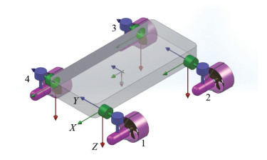
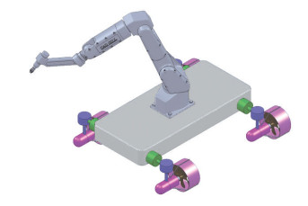
A robotic platform is introduced in this paper. The orientation of each of its thrusters is controlled by two perpendicular servo motors(Fig. 1). With a mechanical arm mounted, the robot has a complete and practical structure for underwater missions(Fig. 2).
|
Fig.1 AUV with two orthogonal servo motors for each thruster |
|
Fig.2 AUV equipped with a manipulator |
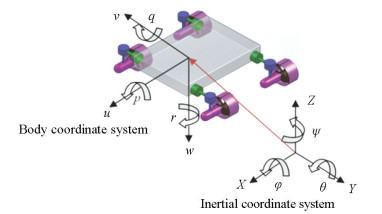
An underwater vehicle has six degrees of freedom including translational movements in three directions and rotational movements around each of three axes. Usually, two types of coordinate systems are used to describe the kinematics and dynamics of the body that includes the earth coordinate system (ECS) frame and the body-fixed coordinate system that is connected to the body (Fig. 3).
|
Fig.3 Body and earth coordinate system with motion variables |
The parameters and variables used in this paper are presented in Table 1. The general governing equation for underwater vehicles in a matrix form in the body of coordinate system is described as
| $ \begin{array}{c} \left( {{\mathit{\boldsymbol{M}}_{{\rm{RB}}}} + {\mathit{\boldsymbol{M}}_{{\rm{ADD}}}}} \right)\mathit{\boldsymbol{\dot \nu }} + \left( {{\mathit{\boldsymbol{C}}_{{\rm{RB}}}} + {\mathit{\boldsymbol{C}}_{{\rm{ADD}}}}} \right)\mathit{\boldsymbol{v}} + \\ \mathit{\boldsymbol{D}}(\mathit{\boldsymbol{\nu }})\mathit{\boldsymbol{\nu }} + \mathit{\boldsymbol{G}}(\mathit{\boldsymbol{\eta }}) = {\mathit{\boldsymbol{\tau }}_\mathit{\boldsymbol{c}}} + {\mathit{\boldsymbol{\tau }}_\mathit{\boldsymbol{d}}} \end{array} $ | (1) |
| Table 1 Variable naming |
where MRB known as the rigid body inertia matrix is defined by
| $ \begin{aligned} &\boldsymbol{M}_{\mathrm{RB}}= \\ &{\left[\begin{array}{cccccc} m & 0 & 0 & 0 & m z_{G} & -m y_{G} \\ 0 & m & 0 & -m z_{G} & 0 & m x_{G} \\ 0 & 0 & m & m y_{G} & -m x_{G} & 0 \\ 0 & -m z_{G} & m y_{G} & I_{x} & -I_{x y} & -I_{x z} \\ m z_{G} & 0 & -m x_{G} & -I_{x y} & I_{y} & -I_{y z} \\ -m y_{G} & m x_{G} & 0 & -I_{x z} & -I_{y z} & I_{z} \end{array}\right]} \end{aligned} $ | (2) |
Also MADD is added mass matrix which is given by
| $ \boldsymbol{M}_{\mathrm{ADD}}=-\left[\begin{array}{c} X_{\dot{u}} & X_{\dot{v}} & X_{\dot{w}} & X_{\dot{p}} & X_{\dot{q}} & X_{\dot{r}} \\ Y_{\dot{u}} & Y_{\dot{v}} & Y_{\dot{w}} & Y_{\dot{p}} & Y_{\dot{q}} & Y_{\dot{r}} \\ Z_{\dot{u}} & Z_{\dot{v}} & Z_{\dot{w}} & Z_{\dot{p}} & Z_{\dot{q}} & Z_{\dot{r}} \\ K_{\dot{u}} & K_{\dot{v}} & K_{\dot{w}} & K_{\dot{p}} & K_{\dot{q}} & K_{\dot{r}} \\ M_{\dot{u}} & M_{\dot{v}} & M_{\dot{w}} & M_{\dot{p}} & M_{\dot{q}} & M_{\dot{r}} \\ N_{\dot{u}} & N_{\dot{v}} & N_{\dot{w}} & N_{\dot{p}} & N_{\dot{q}} & N_{\dot{r}} \end{array}\right] $ | (3) |
In Eq. (1), CRB, CADD are the Coriolis and centripetal matrices for the rigid body and added mass, respectively. D is the hydrodynamic damping matrix and G is defined as gravity. Buoyancy vector is considered negligible in this paper because this AUV has natural buoyancy and the center of buoyancy and mass have coincided.
By using the above matrices and substituting the following relations, the following equations are obtained:
| $ \boldsymbol{M}=\boldsymbol{M}_{\mathrm{RB}}+\boldsymbol{M}_{\mathrm{ADD}}, \boldsymbol{C}(\boldsymbol{v})=\boldsymbol{C}_{\mathrm{RB}}+\boldsymbol{C}_{\mathrm{ADD}} $ |
| $ \boldsymbol{v}=[u, \nu, w, p, q, r]^{\mathrm{T}}, \boldsymbol{\tau}=[X, Y, Z, K, M, N]^{\mathrm{T}} $ |
Thus Eq. (1) will be simplified to
| $ \boldsymbol{M {\dot{v}}}+\boldsymbol{C}(\boldsymbol{v}) \boldsymbol{v}+\boldsymbol{D}(\boldsymbol{v}) \boldsymbol{v}+\boldsymbol{G}(\boldsymbol{\eta})=\boldsymbol{\tau_{c}}+\boldsymbol{\tau_{d}} $ | (4) |
In the above equation, τc represents the forces and moments of underwater vehicle propulsion systems and τd denotes forces and moments related to the environmental disturbances.
2 AUV ControlMost of the underwater vehicles use classic control methods such as PID controller. PID controller is very popular due to its easy implementation and has been used by different researchers like Perrier et al.[24], Prestero[25], Zanoli et al.[26], Gonzalez[27], Santhakumar et al.[28], and Pyo et al.[29]. In the current paper, PID controller is also used for the proposed AUV to control the DP.
After the implementation of the nonlinear-coupled dynamic model of robot in MATLAB-Simulink software and providing an algorithm for the calculation, control inputs must be created by each of thrusters. The orientation of each thruster is determined by comparison of actual trajectory with the desired trajectory of the underwater robot. PD controller is used to control each of the degrees of freedom of the robot. The system block diagram is shown in Fig. 4.

|
Fig.4 Block diagram of the system and controller |
If η is defined as the actual position vector of the robot and ηd as the desired position vector in the ECS (earth coordinate system), the error signal is defined as below:
| $ \boldsymbol{e}=\boldsymbol{\eta_{d}}-\boldsymbol{\eta} $ | (5) |
The error vector of e is a vector with six elements. Assuming that the robot's desired position vector is constant during each control step, the derivative of the error vector will be as follows:
| $ \dot{\boldsymbol{e}}=-\dot{\boldsymbol{\eta}}=-\boldsymbol{J}(\boldsymbol{\eta}) \boldsymbol{v} $ | (6) |
Since the
| $ \begin{gathered} \boldsymbol{\tau}_{\boldsymbol{C}}=\boldsymbol{J}(\boldsymbol{\eta})^{\mathrm{T}}\left(\boldsymbol{K_{P}} \boldsymbol{e}+\boldsymbol{K_{D}} \dot{\boldsymbol{e}}\right) \\ \boldsymbol{\tau}_{{\boldsymbol{C}}}=\left[\boldsymbol{\tau}_{{\boldsymbol{C}} 1}, \boldsymbol{\tau}_{{\boldsymbol{C}} 2}, \boldsymbol{\tau}_{{\boldsymbol{C}} 3}, \boldsymbol{\tau}_{{\boldsymbol{C}} 4}, \boldsymbol{\tau}_{{\boldsymbol{C}} 5}, \boldsymbol{\tau}_{{\boldsymbol{C}} 6}\right]^{\mathrm{T}} \end{gathered} $ | (7) |
In this controller, the KP matrix is a 6×6 proportional matrix and the KD matrix is a 6×6 derivative matrix, both of which are positive definite. Since this control law is obtained, the quantity of the control forces and their orientation need to be found. An instantaneous comparison of the desired path and the path taken by the robot with respect to the ECS yields the error vector e, and at any moment, by having the position and velocity vector of the robot at the previous moment the error vector of e will be obtained according to Eq. (6). Therefore, by selecting the appropriate KD and KP matrices in accordance with Eq. (7), the control vector of τC will be obtained.
By having the instantaneous value of τC, a set of six equations is obtained:
| $ \left\{\begin{array}{l} f_{1 x}+f_{2 x}+f_{3 x}+f_{4 x}=\tau_{C 1} \\ f_{1 y}+f_{2 y}+f_{3 y}+f_{4 y}=\tau_{C 2} \\ f_{1 z}+f_{2 z}+f_{3 z}+f_{4 z}=\tau_{C 3} \end{array}\right. $ |
| $ \left\{\begin{array}{l} -\frac{w}{2} f_{1 z}-\frac{w}{2} f_{2 z}+\frac{w}{2} f_{3 z}+\frac{w}{2} f_{4 z}=\tau_{C 4} \\ -\frac{l}{2} f_{1 z}+\frac{l}{2} f_{2 z}+\frac{l}{2} f_{3 z}-\frac{l}{2} f_{4 z}=\tau_{C 5} \\ \left(\frac{w}{2} f_{1 x}+\frac{l}{2} f_{1 y}\right)+\left(\frac{w}{2} f_{2 x}-\frac{l}{2} f_{2 y}\right)+ \\ \ \ \ \ \ \ \ \ \ \ \ \ \ \ \left(-\frac{w}{2} f_{3 x}-\frac{l}{2} f_{3 y}\right)+ \\ \ \ \ \ \ \ \ \ \ \ \ \left(-\frac{w}{2} f_{4 x}+\frac{l}{2} f_{4 y}\right)=\tau_{C 6} \end{array}\right. $ |
The amount of controlling force required by each thruster is obtained as follows:
| $ \left\{\begin{array}{l} f_{1}=\sqrt{\left(\frac{\tau_{C 1}}{4}+\frac{\tau_{C 6}}{4 w}\right)^{2}+\left(\frac{\tau_{C 2}}{4}+\frac{\tau_{C 6}}{4 l}\right)^{2}+\left(\frac{\tau_{C 3}}{4}-\frac{\tau_{C 4}}{2 w}-\frac{\tau_{C 5}}{2 l}\right)^{2}} \\ f_{2}=\sqrt{\left(\frac{\tau_{C 1}}{4}+\frac{\tau_{C 6}}{4 w}\right)^{2}+\left(\frac{\tau_{C 2}}{4}-\frac{\tau_{C 6}}{4 l}\right)^{2}+\left(\frac{\tau_{C 3}}{4}-\frac{\tau_{C 4}}{2 w}+\frac{\tau_{C 5}}{2 l}\right)^{2}} \\ f_{3}=\sqrt{\left(\frac{\tau_{C 1}}{4}-\frac{\tau_{C 6}}{4 w}\right)^{2}+\left(\frac{\tau_{C 2}}{4}-\frac{\tau_{C 6}}{4 l}\right)^{2}+\left(\frac{\tau_{C 3}}{4}+\frac{\tau_{C 4}}{2 w}+\frac{\tau_{C 5}}{2 l}\right)^{2}} \\ f_{4}=\sqrt{\left(\frac{\tau_{C 1}}{4}-\frac{\tau_{C 6}}{4 w}\right)^{2}+\left(\frac{\tau_{C 2}}{4}+\frac{\tau_{C 6}}{4 l}\right)^{2}+\left(\frac{\tau_{C 3}}{4}+\frac{\tau_{C 4}}{2 w}-\frac{\tau_{C 5}}{2 l}\right)^{2}} \end{array}\right. $ |
The orientation of each of the above forces is determined as follows:
| $ \left\{\begin{array}{l} \cos \left(\theta_{1}\right)_{1}=\frac{f_{1 x}}{f_{1}}, \cos \left(\theta_{2}\right)_{1}=\frac{f_{1 y}}{f_{1}}, \cos \left(\theta_{3}\right)_{1}=\frac{f_{1 z}}{f_{1}} \\ \cos \left(\theta_{1}\right)_{2}=\frac{f_{2 x}}{f_{2}}, \cos \left(\theta_{2}\right)_{2}=\frac{f_{2 y}}{f_{2}}, \cos \left(\theta_{3}\right)_{2}=\frac{f_{2 z}}{f_{2}} \\ \cos \left(\theta_{1}\right)_{3}=\frac{f_{3 x}}{f_{3}}, \cos \left(\theta_{2}\right)_{3}=\frac{f_{3 y}}{f_{3}}, \cos \left(\theta_{3}\right)_{3}=\frac{f_{3 z}}{f_{3}} \\ \cos \left(\theta_{1}\right)_{4}=\frac{f_{4 x}}{f_{4}}, \cos \left(\theta_{2}\right)_{4}=\frac{f_{4 y}}{f_{4}}, \cos \left(\theta_{3}\right)_{4}=\frac{f_{4 z}}{f_{4}} \end{array}\right. $ |
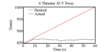
In this paper, at first, the common fixed 6 thruster HAUV was investigated for the feasibility of welding operations only to find out that this model was not suitable for such a mission, and in spite of benefiting from the 6 thrusters, it was incapable of performing such a delicate maneuver. As shown in Fig. 5, if it is assumed that the purpose of the robot is to move in Y direction with controlled velocity, despite making this happen at first, it deviates from the path down the line, hence being unable to carry out precision welding operation.
|
Fig.5 Underwater robot performance in Y direction motion |
Following that, the proposed model previously explained was investigated. The PID controller was used for precise operations such as welding a straight line at a length of 100 mm. At first, the endpoint to the controller was given and it was observed that the robot covered the route and reached the target point. However, considering the fact that welding requires undivided and precise attention, hence it should be implemented with a controlled velocity. A reasonable velocity was thus calculated and applied to the system so that the specified robot could carry out the mission in the desired way. In this regard, the rotation angle of one of the servo motors was considered as a failure so the feasibility of controlling the robot for such operations could be examined. Results were highly desirable as the robot was able to move in the demanded direction with minimal errors.
As can be seen in the three-dimensional figure (Fig. 6), the purpose of the robot is to move in direction of Y from the point with coordinates (1000, 850, 1000) toward the point with coordinates (1000, 1000, 1000). If the aim is doing a precision welding in a straight line with the length of 150 mm, the robot motion in X and Z directions must be zero or at least the minimum amount, making this operation possible. The controller designed for this HAUV (Fig. 7) meets this goal.
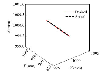
|
Fig.6 AUV (DP) in three dimensions when servo 1 is off |
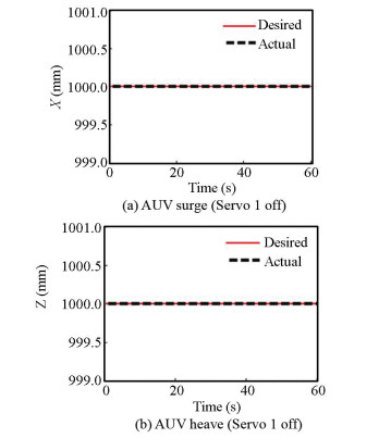
|
Fig.7 Underwater robot performance in X, Z direction motion |
Although at first the HAUV did not follow its desired path in Y direction, but after about 20 s the error disappeared, hence it could do its accurate welding operation in the remaining 100 mm (Fig. 8).
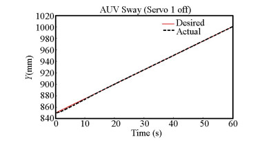
|
Fig.8 Underwater robot performance in Y direction motion |
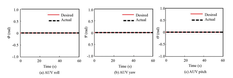
On the other hand, for the AUVs, controlling every six degrees of freedom is important for precise performance. Thus in addition to controlling the AUV translation, some approaches should be provided in order to maintain the other three degrees of freedom including the roll, pitch, and yaw. Therefore, in this paper, three degrees of freedom were added. The results showed that the three degrees of freedom remained stable, providing the ability to perform this type of operation (Fig. 9).
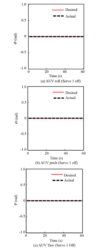
|
Fig.9 Rotational performance of the underwater robot |
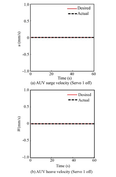
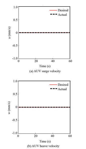
In the case of DP, the AUVs' velocity plays an influential role in robots' accuracy to carry out a precise operation. So a certain velocity was considered to move in Y direction to resemble the operations more closely to real conditions. In regard to Fig. 7, as there were not any movements in X and Z directions, their velocities should be zero. Results of these velocities are shown in Fig. 10.
|
Fig.10 AUV velocity in X, Z direction |
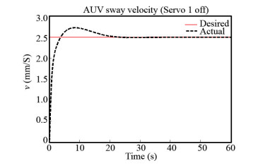
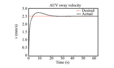
But for movement in Y direction, the AUV's velocity was adjusted and from the 20th second (which is supposed to be the start of the operation) until the 60th seconds (end of the operation), the robot covered 2.5 mm in each second. As shown in Fig. 11, the robot in the first 20 seconds moved forward with a minor error or deviation from the desired velocity but then reached the desired velocity and continued its path.
|
Fig.11 AUV velocity in Y direction |
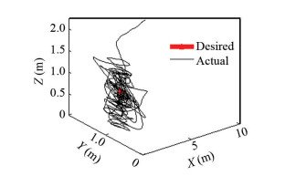
As mentioned earlier in the DP definition, the AUV must be able to maintain its position in a fixed location to carry out such an operation, but in this robot if a degree of freedom of the servo motor has been disabled then the robot will not be able to reach the predetermined spot or remain in that position to begin such an accurate intervention. To clarify the performance of the robot, its 3-dimensional motion is shown in Fig. 12.
|
Fig.12 AUV DP in three dimensions when Servo 1 is off |
Thus, as observed, despite the failure of one degree of freedom of the robot's servo motor, it will be able to perform welding operation perfectly but it will not be able to properly reach the desired location. On the other hand, if the servo motor fails in the operation site, the robot will be able to finish its mission.
For further study of the proposed robot's performance under different conditions and to consider the types of events regarding the difficult conditions in the unknown ocean environment that is possible to occur for the robot, the failure of a thruster was studied to investigate the performance of the robot under such circumstances which is not far away from reality.
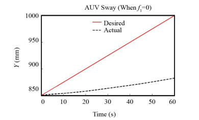
To investigate this issue, it was assumed that one of the thrusters is not working, hence not exerting any force whatsoever (Fig. 13). The presented robot failed to achieve the desired goal despite the significant effort it put in, proving that all the thrusters should be active.
|
Fig.13 Underwater robot performance in Y direction motion |
Thus for operations with high accuracy, the existence of the four thrusters with two degrees of freedom for each of them is necessary, which helps the AUV to be able to achieve the desired position, performing precise interventions (Fig. 14).
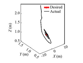
|
Fig.14 AUV DP in three dimensions to the desired location |
After reaching and remaining on the desired position, to perform the welding operation it must move with reasonable velocity along Y direction to provide the possibility of welding, which became possible with the help of all four thrusters, as shown in Fig. 15.
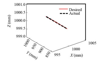
|
Fig.15 AUV DP in three dimensions |
As mentioned earlier, the other robots' degrees of freedom should be completely controlled, which is fulfilled with the help of the designed controller for this robot. In Fig. 16, changes in X and Z directions are shown to be perfectly balanced.
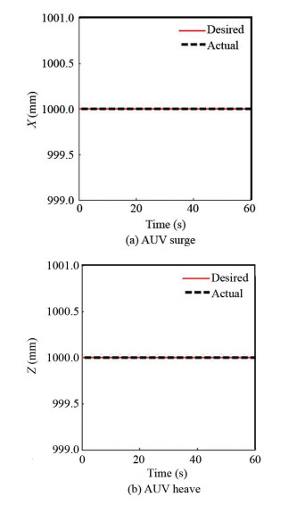
|
Fig.16 Underwater robot performance in X, Z direction motion |
In Fig. 17, the traveled route in Y direction is shown, which suggests that after 20 s the AUV can accomplish its mission perfectly and as mentioned earlier, the rotational degrees of freedom should be zero, which is based on Fig. 18 showing they are well controlled.
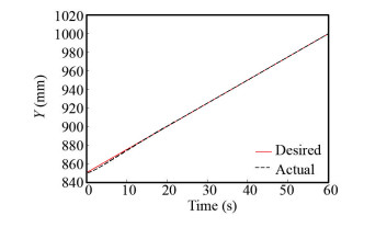
|
Fig.17 Underwater robot performance in Y variable motion |
|
Fig.18 Underwater robot rotational performance |
After 20 s, the robot reached the desired velocity value of 2.5 mm/s in Y direction and zero in X and Z directions as it did not have any movement in the said directions, indicating the flawless performance of the robot throughout the welding operation (Figs. 19-20).
|
Fig.19 AUV velocity in X, Z direction |
|
Fig.20 AUV velocity in Y direction |
4 Conclusions
In this paper, an HAUV with high maneuverability and DP capability is proposed to perform accurate operations such as underwater welding. First, a common model with six thrusters was tested, which was not able to carry out such intervention. Then the model proposed in this paper was examined. For optimal performance of this robot, a PID controller was designed. Staying true to the real-life situations, the probable conditions that the robot might encounter within the natural environment, such as the failure of a servo motor and the possibility of thruster failure, were studied. The results showed that the common fixed 6-thruster HAUV was not able to perform such delicate mission, but the presented robot with four thrusters, in case of a servo motor malfunction, was able to perfectly manage the welding operation. However, it failed in reaching the pre-determined point and staying there afterward. At last, the results showed that the best performance happened when all the four thrusters with their servo motors were working properly and as intended, making the robot reach the desired spot, being stable in that location and performing an accurate intervention. The present PID controller has an absolutely remarkable performance in controlling the DP for this HAUV, considering the difficult conditions for doing a meticulous job in a small space and in the desired time frame.
| [1] |
Panagou D, Kyriakopoulos K J. Dynamic positioning for an underactuated marine vehicle using hybrid control. International Journal of Control, 2014, 87(2): 264-280. DOI:10.1080/00207179.2013.828853 (  0) 0) |
| [2] |
Sørensen A J. A survey of dynamic positioning control systems. Annual Reviews in Control, 2011, 35(1): 123-136. DOI:10.1016/j.arcontrol.2011.03.008 (  0) 0) |
| [3] |
Du J L, Yang Y, Wang D H, et al. A robust adaptive neural networks controller for maritime dynamic positioning system. Neurocomputing, 2013, 110: 128-136. DOI:10.1016/j.neucom.2012.11.027 (  0) 0) |
| [4] |
Fay H. Dynamic Positioning Systems: Principles, Design and Applications, 1st ed. Paris: Editions Technip, 1990. vii.
(  0) 0) |
| [5] |
Gao J, Proctor A, Bradley C. Adaptive neural network visual servo control for dynamic positioning of underwater vehicles. Neurocomputing, 2015(167): 604-613. DOI:10.1016/j.neucom.2015.04.028 (  0) 0) |
| [6] |
Yuh J. Design and control of autonomous underwater robots: a survey. Autonomous Robots, 2000, 8(1): 7-24. DOI:10.1023/a:1008984701078 (  0) 0) |
| [7] |
Leonard N E. Control synthesis and adaptation for an underactuated autonomous underwater vehicle. IEEE Journal of Oceanic Engineering, 1995, 20(3): 211-220. DOI:10.1109/48.393076 (  0) 0) |
| [8] |
Pettersen K Y, Egeland O. Position and attitude control of an underactuated autonomous underwater vehicle. Proceedings of 35th IEEE Conference on Decision and Control. Piscataway: IEEE, 1996, 987-991. DOI:10.1109/CDC.1996.574614 (  0) 0) |
| [9] |
Aguiar A P, Pascoal A M. Regulation of a nonholonomic autonomous underwater vehicle with parametric modeling uncertainty using lyapunov functions. Proceedings of the 40th IEEE Conference on Decision and Control. Piscataway: IEEE, 2001, 4178-4183. DOI:10.1109/CDC.2001.980841 (  0) 0) |
| [10] |
Riedel J S. Shallow water stationkeeping of an autonomous underwater vehicle: the experimental results of a disturbance compensation controller. OCEANS 2000 MTS/IEEE Conference and Exhibition. Conference Proceedings (Cat. No. 00CH37158). Piscataway: IEEE, 2000. 1017-1024. DOI: 10.1109/OCEANS.2000.881733.
(  0) 0) |
| [11] |
Antonelli G, Chiaverini S, Sarkar N, et al. Adaptive control of an autonomous underwater vehicle: experimental results on ODIN. IEEE Transactions on Control Systems Technology, 2001, 9(5): 756-765. DOI:10.1109/87.944470 (  0) 0) |
| [12] |
Aguiar A P, Pascoal A M. Dynamic positioning of an underactuated AUV in the presence of a constant unknown ocean current disturbance. IFAC Proceedings Volumes, 2002, 35(1): 283-288. DOI:10.3182/20020721-6-ES-1901.01272 (  0) 0) |
| [13] |
Liu S Y, Wang D W, Poh E K. A nonlinear observer for AUVs in shallow water environment. Proceedings of the 2004 IEEE/RSJ International Conference on Intelligent Robots and Systems. Piscataway: IEEE, 2004, 1130-1135. DOI:10.1109/IROS.2004.1389548 (  0) 0) |
| [14] |
Hoang N Q, Kreuzer E. Adaptive PD-controller for positioning of a remotely operated vehicle close to an underwater structure: theory and experiments. Control Engineering Practice, 2007, 15(4): 411-419. DOI:10.1016/j.conengprac.2006.08.002 (  0) 0) |
| [15] |
Garcia-Valdovinos L G, Salgado-Jimenez T. On the dynamic positioning control of underwater vehicles subject to ocean currents. Proceedings of 2011 8th International Conference on Electrical Engineering, Computing Science and Automatic Control. Piscataway: IEEE, 2011, 1-6. DOI:10.1109/ICEEE.2011.6106590 (  0) 0) |
| [16] |
Bessa W M, Dutra M S, Kreuzer E. Dynamic positioning of underwater robotic vehicles with thruster dynamics compensation. International Journal of Advanced Robotic Systems, 2013, 10: 1-8. DOI:10.5772/56601 (  0) 0) |
| [17] |
Gao J, Proctor A A, Shi Y, et al. Hierarchical model predictive image-based visual servoing of underwater vehicles with adaptive neural network dynamic control. IEEE Transactions on Cybernetics, 2016, 46(10): 2323-2334. DOI:10.1109/TCYB.2015.2475376 (  0) 0) |
| [18] |
Gertler M, Hagen G R. Standard Equation of Motion for Submarine Simulation. Washington D.C. : Naval Ship Research and Development Center, 1967. 5-12.
(  0) 0) |
| [19] |
Logan C L. A comparison between H-infinity/Mu-synthesis control and sliding-mode control for robust control of a small autonomous underwater vehicle. Proceedings of IEEE Symposium on Autonomous Underwater Vehicle Technology (AUV'94). Piscataway: IEEE, 1994, 399-416. DOI:10.1109/AUV.1994.518653 (  0) 0) |
| [20] |
Yang C. Modular Modeling and Control for Autonomous Underwater Vehicle. Singapore: National University of Singapore, 2007. 18-26.
(  0) 0) |
| [21] |
Ribas D, Palomeras N, Ridao P, et al. Girona 500 AUV: from survey to intervention. IEEE/ASME Transactions on Mechatronics, 2012, 17(1): 46-53. DOI: 10.1109/TMECH.2011.2174065.
(  0) 0) |
| [22] |
Zhao S, Yuh J. Experimental study on advanced underwater robot control, robotics. IEEE Transactions on Robotics, 2005, 21(4): 695-703. DOI:10.1109/TRO.2005.844682 (  0) 0) |
| [23] |
Shamshiri F, Ghasemi R H. Trajectory controller design for an autonomous underwater vehicle for in-water ship hull inspection. Modares Mechanical Engineering, 2015, 15: 12-22. (  0) 0) |
| [24] |
Perrier M, Canudas-de-Wit C. Experimental comparison of PID vs. PID plus nonlinear controller for subsea robots. Autonomous Robots, 1996, 3(2-3): 195-212. DOI:10.1007/BF00141155 (  0) 0) |
| [25] |
Prestero T. Verification of a Six-Degree of Freedom Simulation Model for the REMUS Autonomous Underwater Vehicle. Cambridge: Massachusetts Institute of Technology, 2001: 86-93.
(  0) 0) |
| [26] |
Zanoli S M, Conte G. Remotely operated vehicle depth control. Control Engineering Practice, 2003, 11(4): 453-459. DOI:10.1016/S0967-0661(02)00013-8 (  0) 0) |
| [27] |
Gonzalez L A. Design, Modelling and Control of an Autonomous Underwater Vehicle. Perth: The University of Western Australia, 2004. 72-74.
(  0) 0) |
| [28] |
Santhakumar M, Asokan T. A self-tuning proportional-integral-derivative controller for an autonomous underwater vehicle, based on Taguchi method. Journal of Computer Science, 2010, 6(8): 862-871. DOI:10.3844/jcssp.2010.862.871 (  0) 0) |
| [29] |
Pyo J, Joe H-G, Kim J-H, et al. Development of hovering-type AUV "cyclops" for precision observation. Proceedings of 2013 OCEANS-San Diego. Piscataway: IEEE, 2013. 1-5. DOI: 10.23919/OCEANS.2013.6741060.
(  0) 0) |
 2021, Vol. 28


