2. Changchun Changguang Ruishi Photoelectric Technology Co., Ltd, Changchun 130102, China;
3. School of Mechanical and Aerospace Engineering, Jilin University, Changchun 130022, China;
4. North Vehicle Research Institute, Beijing 100072, China
Compared with the traditional wheeled or tracked robotic platforms, legged robot could do some dangerous work due to the better passing ability and adaptability on unconventional ground, such as planetary surface exploration, disaster prevention, detection of enemy's situation, rescue, etc. Therefore, legged robots have always been a popular choice for robotic researchers[1-3]. The leg plays a crucial role in the locomotion of the robot, so it is worthwhile to design a mechanical leg with special functions and performances. In recent years, researchers have carried out extensive research and made a series of achievements. The quadruped robot Big Dog developed by Boston Dynamics and the hydraulic-driven quadruped robot HyQ developed by the Italian University of Technology both adopted the telescopic legs configuration, which is beneficial to reduce the damage of ground impact[4-5]. The "Cheetah" robot developed by Boston Dynamics took the musculoskeletal structure of the hindlimb of cheetah as the bionic prototype. Its leg mechanism can effectively reduce the rotational inertia of the legs and help reduce the torque of the motor[6-8]. Ananthanarayanan et al.[9] developed a lightweight mechanical leg based on cheetah's tendon-bone co-location architecture and the interaction mechanism between the joints and muscles, which can guarantee the required stiffness and strength and avoid large bending moments while having lightweight characteristic. Nie et al.[10] designed a bionic mechanical leg based on the hindlimb of the horse, which adopts a series of elastic elements, with high agility and low vibration.
The legged robot has better trafficability than wheeled or tracked robotic platform on unconventional ground, but they tend to have high vibration and energy consumption during operation. Energy efficiency and vibration damping are important goals of the research on legged robot[11]. These robots and mechanical legs have their own superior performance, but there is still much room for improvement in energy-efficient and vibration-damping performance. The hindlimb of the African ostrich has a robust, long-lasting, and high-speed running ability. Take the ostrich hindlimb as the bionic prototype. Applying the superior performance of the ostrich hindlimb to the design of the robot's leg mechanism is an effective way to develop the mechanical leg with energy-efficient and vibration-damping performance. The ostrich-shaped robot FastRunner, jointly developed by the Massachusetts Institute of Technology and the Florida Institute for Human and Machine Cognition, uses a series of elastic elements in the leg to store part of the energy consumed during operation and release the energy when necessary, which is conducive to energy efficiency and vibration damping. Because the stiffness coefficient of the elastic component is always constant during the movement, more energy is consumed in the process of compressing the elastic component, so that the energy-saving effect is weakened[12]. The bionic ostrich robot developed by IHMC can run at a speed of 16 km/h without any computer aid or sensors. However, it still needs to be further improved in terms of energy efficiency and vibration damping[13]. Moreover, the researchers lacked the mechanism analysis of the biological prototype, and did not consider the passive rebound characteristic of the ostrich's intertarsal joint.
In this paper, the law of the locomotion of the ostrich hindlimb and the general anatomy of ostrich hindlimb in the running state were studied, and the passive rebound characteristic of the intertarsal joint of the ostrich hindlimb as well as the variable mechanism of the leg stiffness were analyzed. Using engineering bionic technology, a bionic mechanical leg was designed, and the kinematics analysis and locomotion simulation analysis were conducted. The bionic mechanical leg designed in this paper performed with the characteristics of high efficiency, energy saving, and buffer damping, which can be used as the leg mechanism of biped robot for field transportation and deep space exploration.
1 Bionic Analysis of Mechanical Leg 1.1 Structural Analysis of Ostrich HindlimbThe Africanostrich (Struthio camelus) is the fastest bipeds in the world. Adult ostrich has a mass of about 140 kg and a running speed of about 60 km/h, which can be maintained for about 30 min. The sprint speed of the ostrich is over 70 km/h. The ostrich hindlimb is strong and powerful, with the ability of robust, long-lasting, and high-speed running[14-15]. The intertarsal joint has the characteristics of passive rebound and variable stiffness, which is conducive to further reducing energy consumption during locomotion[16]. Based on the principle of engineering bionics, the superior performance of the ostrich hindlimb is applied to the design of the leg mechanism of the biped robot.
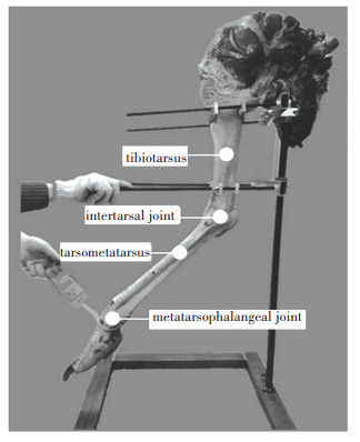
The biological sample in this paper was selected from the healthy African ostrich in the ostrich farm in Harbin, Heilongjiang Province, China, as shown in Fig. 1. Before sampling, the ostrich was raised in an open outdoor field and provided with unlimited food and water. The ethical approval was granted by the Jilin University Animal Experimental Ethics Testing Center. By gross anatomy, the biological parameters of the ostrich are shown in Table 1. By testing the locomotion parameters of the ostrich hindlimb and combining with the biological anatomical analysis, the following facts are obtained (taking the right leg as an example): 1) The joints of the ostrich hindlimb mainly include hip joint, knee joint, ankle joint (intertarsal joint), and metatarpophalangeal joint. 2) The muscle is mainly concentrated near the femur at the proximal end, and the calf and foot are mainly composed of the bone and the attached soft tissues (ligaments and tendons). The tibia and tarsometatarsus are of light weight, which reduces the mass at the distal end of the leg, thereby reducing its rotational inertia and contributing to high efficiency and energy saving. 3) After long-term evolution, the ostrich has only two toes (Ⅲ, Ⅳ toe), of which the Ⅲ toe is relatively thicker, and the strength of the metatarsophalangeal joint is significantly enhanced. 4) In different locomotion states, animals can improve their locomotion efficiency by adjusting the output stiffness characteristic of their legs[17-18].
|
Fig.1 Sample of the ostrich hindlimb |
| Table 1 Biological model parameters of the ostrich hindlimb |
1.2 Passive Rebound Characteristic of the Intertarsal Joint
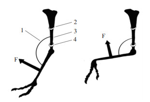
Unlike the hip and knee joints, the intertarsal joint has no muscle tissue. Combined with the structural characteristics of the intertarsal joint, its passive structural tissues (such as ligaments) play an important role in joint stability and motor control. Schaller et al.[19] studied the ligament system of the ostrich intertarsal joint and its interaction with articular surface protuberance, and confirmed the important role of the ligament system in the locomotion of the ostrich. Studies have shown that the intertarsal joint is a joint that is capable of secreting lubricating fluid and having rolling and sliding locomotion within the range of flexion/extension of the joint[20]. As shown in Fig. 2, the tibia is fixed, and the angle of the intertarsal joint is changed by manually manipulating the tarsometatarsus. When the angle of the intertarsal joint is greater than 125° and less than 168°, the tarsometatarsus is released. If the external force is removed, the tarsometatarsus automatically and rapidly swings to the intertarsal joint angle, which is 168°; when the angle between the intertarsal joint is less than 105°, the metatarsus is released, the external force is removed, and the tarsometatarsus rapidly swings to 80° position.
|
1. Intertarsal joint; 2. Fixed end 1; 3. Tibia; 4. Fixed end 2 Fig.2 Schematic diagram of passive of rebound characteristics of the intertarsal joint |
1.3 Simplification and Parameter Design of Biological Model
In this paper, the ostrich hindlimb was used as the bionic prototype. Through the anatomy of the ostrich hindlimb, it was found that the bones of the pelvic limb are also divided into pelvic girdle bones and mobility part bones. The pelvic girdle includes the ilium, sciatic, and pubic bones. The mobility part bones include femur, tibia, metatarsus, and phalanges[21]. The pelvic girdle is mainly used to support the weight of the posterior part and transfer the thrust of the hindlimb. In the design of the bionic machine, the pelvic girdle was taken as a whole, and it was simplified as a cuboid. In the locomotion process of the ostrich, the mobility part bones play a supporting role. The femur is a tubular long bone. Compared with the tibia and tarsometatarsus, the femur is short but very strong. Many of muscles in the ostrich hindlimb are concentrated in the vicinity of the femur, and most of the mass and energy are concentrated here. In the design of bionic mechanical leg, the femur was simplified as a hollow tube, and was used as the power source for the bionic mechanical leg. The tibia and metatarsus are light in weight and long in length, but they can can bear gravity and the impact of the ground. Therefore, they were regarded as rigid bodies and replaced by a small mass rod[22-23]. The intertarsal joint between the tibia and the metatarsus has the passive rebound characteristic. Moreover, When ostrich is walking and running, compared with the passive rebound characteristic of forward extension (the intertarsal joint angle automatically rebounds from 125° to 168°), the passive rebound characteristic of the intertarsal joint during flexion are not so obvious. Therefore, the passive rebound characteristic of the intertarsal joint extension was selected as the bionic model. The phalange include the Ⅲ toe and the Ⅳ toe, which can be simplified as a whole, as a grounding component of the mechanical leg.
The rigid elements cooperated to simulate the locomotion pattern of the ostrich and realize the passive rebound characteristic of the intertarsal joint. At the same time, the elastic components such as inner and outer springs were used to simulate the function of the tendon, and finally the bionic mechanical leg with rigid-flexible coupling and energy-efficient and vibration-damping characteristics was designed.
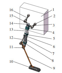
2 Structure Design of Bionic Mechanical Leg 2.1 Bionic Design of Integral StructureBased on the structural characteristic of the ostrich hindlimb and the passive rebound characteristic of the intertarsal joint, a bionic mechanical leg was designed. The overall structure is shown in Fig. 3. The leg crank is driven by a motor, and the motion form of the motor is continuous rotation. When the motor was in reciprocating motion, the continuous cycle of stopping and driving produced more energy consumption, and continuous rotation can take advantage of inertia. Therefore, compared with the driving mode of the reciprocating motion of the conventional power source, the continuous rotation of the motor is more energy-efficient.
|
1. Body; 2. Motor; 3. Crank; 4. Fixed slider (F); 5. Slide block; 6. The structure of inner spring mechanism; 7. Outer spring; 8. Limit stop; 9. Tarsometatarsus; 10. Toe; 11. Pin shaft; 12. Fibula; 13. Pressure spring; 14. Tibia; 15. Femur; 16. Rocker Fig.3 Geometry of the structure of bionic mechanical leg |
2.2 Operating Principle of the Bionic Mechanical Leg
The motor drives the crank to rotate counterclockwise through the reducer, and each time the crank rotates 360°, it corresponds to a walking cycle of the bionic mechanical leg. The trajectory of the tibia and femur articulation points (the knee joint) is approximately half an ellipse. While ensuring the swing amplitude of the leg, the upper and lower amplitudes of the body are also small, so that the overall mechanism can be stably moved. The fixed slider and the body are hinged at point F so that they can only rotate around the hinge point F, as shown in Fig. 3.
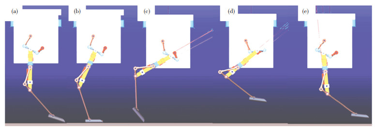
During the whole stance phase, the bionic mechanical leg is affected by the impact load from the ground. In the early stance phase, when the toe is about to touch the ground, the electromagnetic lock starts to work and pushes the compression spring plate out of the tibia. Under the ground reaction force, the tarsometatarsus acts on the moving slider through the fibula, so that the moving slider slides down the tibia. At this point, the compression spring plate protrudes from the tibia under the action of the electromagnetic lock, and the moving slider slides and presses downward. The spring plate contacts, and the inner spring is compressed by the compression spring plate while compressing the outer spring. At this point, the impact force of the inner spring and outer spring on the ground plays a role of buffering and vibration damping, and the lost part of mechanical energy is transformed into elastic potential energy. In addition, because the stiffness coefficient of the inner spring is much greater than that of the outer spring, it plays a main supporting role. In the late stance phase, the inner and outer springs recover the deformation and release the elastic potential energy. Under the rebound effect of the inner and outer springs, the sliding block slides upward along the fibula, and acts on the tarsometatarsus through the fibula, realizing the "kicking off" action. In this way, the kinetic energy of the bionic mechanical leg is increased.
After the stance phase, the bionic mechanical leg enters the lift-off phase. In the early lift-off phase, when the toe is about to leave the ground, the electromagnetic lock works again and retracts the compression spring plate into the tibia. The motion of the tibia can be divided into rotation around hinged joint point F and sliding upward along the fixed slider under the drive of the crank rocker mechanism and the limitation of the fixed slider. At the same time, the fixed slider acts on the moving slider through the pressure spring, so that it slides down along the tibia. Because the compression spring plate retracts into the tibia, the moving slider cannot contact with the compression spring plate, and thus does not interact with the inner spring. At this point, the moving slider compresses the outer spring, storing elastic potential energy, and at the same time, the tarsometatarsus is raised through the fibula to complete the "bending leg" action. In the late lift-off phase, the motion of the tibia can be divided into the rotation around the hinge point F and sliding downward along the fixed slider. At this point, under the rebound of the outer spring, the moving slider moves upward along the tibia, and through the fibula to stretch the tarsometatarsus.The passive extension of the intertarsal joint of the ostrich hindlimb is realized, and the action of "stretching the legs" is completed. The specific locomotion process is shown in Fig. 4. Referring to the rebound characteristic of the intertarsal joint of the ostrich hindlimb, the bionic mechanical leg interacts with the ground to convert the lost energy into the elastic potential energy of the inner and outer springs, and is released during the process of "ground kicking, " which is beneficial to reduce energy loss. In addition, a large number of elastic components are adopted in the bionic mechanical legs, which are conducive to buffering and vibration reduction, reducing the impact of ground damage and achieving the purpose of energy-efficiency and vibration damping[24-25].
|
(a)The early stance phase; (b) The middle stance phase; (c) The late stance phase; (d) The early lift-off phase; (e) The late lift-off phase Fig.4 Simulation images of the bionic mechanical leg walking on flat ground |
2.3 Bionic Design of the Passive Rebound Mechanism
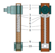
According to the passive rebound characteristic of the ostrich intertarsal joint, the passive rebound mechanism of the bionic mechanical leg was designed. The passive rebound mechanism adopts inner and outer springs, mainly including fixed slider, tibia, pressure spring, moving slider, fibula, outer spring, baffle, metatarsus, pin shaft, and inner spring mechanism, as shown in Fig. 5. The outer spring has a small stiffness coefficient, which is the main part to achieve the passive rebound characteristic of the ostrich intertarsal joint. The stiffness coefficient of the inner spring is much greater than that of the outer spring. In the lift-off phase, the inner spring does not function, while in the stance phase, the inner spring starts to work, which plays a role of supporting, vibration damping, as well as energy saving.
|
1. Tibia; 2. Slide block; 3. Pressure spring block; 4. Baffle; 5. Linear actuator; 6. The base of pressure spring block; 7. Inner spring; 8. Smooth edged rolls; 9. Limit stop; 10. The base of inner spring Fig.5 Geometry of the structure of inner spring mechanism |
The inner spring does not work during the lift-off phase, but works during the stance phase. In the early lift-off phase, the electromagnetic lock acts on the two compression spring plates to move them in opposite directions, and the compression spring plate is quickly retracted into the inside of the tibia so that it does not affect the sliding of the moving slider on the tibia. When the compression spring plate is fully retracted into the tibia, the fixed slider squeezes the moving slider down the tibia through the pressure spring to compress the outer spring and store the elastic potential energy. In the late lift-off phase, the moving slider moves upward along the tibia under the rebound of the outer spring. The angle between the metatarsus and the tibia reaches 168°. During the brief contact of the foot with the ground, the compression spring plates are separated from each other under the action of the electromagnetic lock, so that the compression spring plate extends out of the tibia. In the early stance phase, the moving slider moves down the tibia to compress the outer spring, and at the same time compresses the inner spring through the compression spring plate, converting part of the mechanical energy lost on contact with the ground into elastic potential energy, and releasing it in the late stance phase. Compared with the rigid self-locking mechanism between the tibia and the metatarsus, under the condition of the normal locomotion of the robot, the combination of inner and outer springs helps to reduce the energy consumption of the robot's locomotion, and reduce the vibration and the risk of damage to the mechanism caused by the rigid contact with the ground[26]. In addition, the inner spring does not work during the lift-off phase, which can effectively reduce the motor running load and reduce energy consumption.
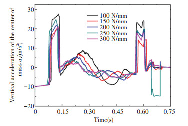
3 Motion Simulation AnalysisThe bionic mechanical leg was modeled with SOLIDWORKS, and then the three-dimensional model of the bionic mechanical leg was imported into ADAMS for motion simulation[27]. The pressure spring is located between the moving slider and the fixed slider, which plays a role of buffering and vibration damping to prevent rigid collision between the moving slider and the fixed slider from causing the bionic mechanical leg to fail to operate normally. This paper mainly studies the energy-saving and vibration-damping effects of the inner and outer spring mechanisms, so the selection process of the pressure spring parameters is no longer elaborated. Through the motion simulation experiment, the selection process of the stiffness coefficient of the pressure spring is shown in Table 2. The main function of the outer spring is to achieve the passive rebound characteristic of the intertarsal joint of the ostrich hindlimb robot. In the late lift-off phase, when the tibia moves down the fixed slider, the moving slider can move upward along the tibia under the rebound of the outer spring, so that the angle between the metatarsus and the tibia (the intertarsal joint angle) is extended to 168°. When the spring is compressed in the early lift-off phase, the greater the stiffness coefficient of the outer spring, the greater the torque of the motor. Therefore, on the premise of achieving passive rebound, it is better to have a smaller stiffness coefficient of the outer spring. The motion simulation in this paper mainly studies the influence of the variation of inner spring stiffness coefficient on the vertical acceleration of the body centroid (in the stance phase) and the power consumption of the motor. Under the premise of ensuring the normal operation of the bionic mechanical legs, by changing the inner spring stiffness coefficient, multiple sets of the curves of vertical acceleration of the body centroid (Fig. 6) and motor power consumption curves (Fig. 7) were generated. The motion simulation was carried out, and the motor energy consumption using inner and outer spring mechanism was compared with that without inner and outer spring mechanism to verify whether using inner and outer spring mechanism can effectively reduce motor energy consumption. The horizontal direction was set to the X axis and the vertical direction was the Y axis. The initial position of the simulation is the position of the toe just off the ground, and the simulation ends when the toe is again off the ground (crank rotates 360°). The locomotion of the body was restricted in the sagittal plane. The structural parameters of the bionic mechanical leg refer to the actual size of the ostrich hindlimb. In order to simplify the calculation in the later phase, the original data was taken as integer. When the femur size was applied according to the original biological size, the trajectory of the foot end of the bionic mechanical leg was quite different from that of the real ostrich, so the femur length was taken as a single variable for optimization to obtain the optimal size of the femur. According to the actual running state of the ostrich, the minimum angle of the intertarsal joint in the stance phase was determined to be 160°. In order to ensure the smoothness of the locomotion, the minimum stiffness coefficient of the inner spring during the simulation of the bionic mechanical leg in the stance phase should ensure the intertarsal joint angle is no less than 152°. The locomotion parameters were designed as shown in Table 3.
| Table 2 The valid values of vertical acceleration of the body centroid in the stance phase |
|
Fig.6 Curves of vertical acceleration of the body centroid in the stance phase |

|
Fig.7 Curves of power consumption of motor |
| Table 3 Design parameters of the bionic mechanical leg in simulation |
The vertical acceleration of the body centroid and the power consumption of the motor under different inner spring stiffness coefficients were compared. Effective value pairs of vertical acceleration of the body centroid corresponding to different stiffness coefficients of inner springs are shown in Table 2, where effective value of acceleration ψ is calculated according to Eq.(1):
| $ \mathit{\Psi } = \sqrt {\mathop {\lim }\limits_{N \to \infty } \frac{1}{N}\sum\limits_i^N {a_{yi}^2} } $ | (1) |
where ay is the vertical acceleration of the body centroid, N is the number of ay.
The power consumption corresponding to different stiffness coefficients of the inner spring is integrated with time, and different energy consumption comparisons are obtained, as shown in Table 4.
| Table 4 Power consumption of the motor |
From the simulation calculation results, it can be concluded that the stiffness coefficient corresponding to the minimum effective value of the vertical acceleration of the body centroid and the minimum value of the motor energy consumption are 150 and 200 N/mm, respectively. Since the effective value of the vertical acceleration of the body centroid in Table 4 is small, and the article pays more attention to the energy-saving index, so the optimum stiffness coefficient of the inner spring is 200 N/mm.
Set the stiffness coefficient of the inner spring as 200 N/mm and the stiffness coefficient of the outer spring as 10 N/mm to verify that the inner and outer spring mechanism can effectively reduce motor energy consumption. Since the inner spring and outer spring are connected in parallel, it can be equivalent to a large spring with a stiffness coefficient of 210 N/mm. Therefore, the stiffness coefficient combination of inner spring andouter spring in Table 5 was used for simulation test, and the motor power consumption curve was obtained, as shown in Fig. 8.
| Table 5 Stiffness coefficient of inner and the outer spring |

|
Fig.8 Curves of power consumption of motor |
Under different test conditions, the power consumption is integrated with time, and the energy consumption pairs are shown in Table 6.
| Table 6 Power consumption of motor under different test conditions |
Table 6 shows that the energy consumption can be effectively reduced by using the inner and outer spring mechanism. The energy consumption of the motor with inner and outer spring mechanism is about 51.41 kJ, while that of the motor without the inner and outer spring mechanism is about 186.87 kJ. Therefore, the inner and outer spring mechanism is used to effectively reduce the energy consumption of the motor by about 72.49%.
In the mechanism design, the total weight of the leg mechanism is about 1.97 kg, only accounting for 8.97% of the design weight of the robot, which is similar to the proportion of the bionic prototype. The main mass of the robot is focused on the proximal end to reduce the rotational inertia of the leg, which is conducive to realizing the purpose of energy-efficiency.
4 ConclusionsThe ADAMS was used to simulate the locomotion of the bionic mechanical leg. The influence of the change of the inner spring stiffness coefficient on the vertical acceleration of the body centroid (in the stance phase) and the power consumption of the motor was studied. By changing the stiffness coefficient of the inner spring, the curve of the acceleration of the body centroid and the power consumption of the motor was obtained. It can be concluded from the simulation calculation that the optimum stiffness coefficient of the inner spring is 200 N/mm. The inner spring stiffness coefficient was selected as 200 N/mm, and the comparison test was carried out. The results show that the inner and outer spring mechanism can effectively reduce the energy consumption of the motor.
| [1] |
Kazemi H, Majd V J, Moghaddam M M. Modeling and robust backstepping control of an underactuated quadruped robot in bounding motion. Robotica, 2013, 31(3): 423-439. DOI:10.1017/S0263574712000458 (  0) 0) |
| [2] |
Ugurlu B, Havoutis I, Semini C, et al. Dynamic trot-walking with the hydraulic quadruped robotHyQ: analytical trajectory generation and active compliance control. Proceedings of the 2013 IEEE/RSJ International Conference on Intelligent Robots and Systems. Piscataway: IEEE, 2013, 6044-6051. DOI:10.1109/IROS.2013.6697234 (  0) 0) |
| [3] |
Winkler A W, Mastalli C, Havoutis I, et al. Planning and execution of dynamic whole-body locomotion for a hydraulic quadruped on challenging terrain. Proceedings of the 2015 IEEE International Conference on Robotics and Automation (ICRA). Piscataway: IEEE, 2015, 5148-51541. DOI:10.1109/ICRA.2015.7139916 (  0) 0) |
| [4] |
Raibert M, Blankespoor K, Nelson G, et al. BigDog, the rough-terrain quadruped robot. IFAC Proceedings Volumes, 2008, 41(2): 10822-10825. DOI:10.3182/20080706-5-KR-1001.01833 (  0) 0) |
| [5] |
Semini C, Tsagarakis N G, Guglielmino E, et al. Design of HyQ—a hydraulically and electrically actuated quadruped robot. Journal of Systems and Control Engineering, 2011, 225: 831-849. DOI:10.1177/0959651811402275 (  0) 0) |
| [6] |
Wang C L, Wand S G. Bionic control of cheetah bounding with a segmented spine. Applied Bionics and Biomechanics, 2016, 2016: 1-12. DOI:10.1155/2016/5031586 (  0) 0) |
| [7] |
Seok S, Wang A, Chuah M Y, et al. Design principles for highly efficient quadrupeds and implementation on the MIT Cheetah robot. Proceedings - IEEE International Conference on Robotics & Automation. Piscataway: IEEE, 2013. DOI:10.1109/ICRA.2013.6631038 (  0) 0) |
| [8] |
Seok S, Wang A, Chuah M Y, et al. Design principles for energy-efficient legged locomotion and implementation on the MIT cheetah robot. IEEE/ASME Transactions on Mechatronics, 2015, 20(3): 1117-1129. DOI:10.1109/TMECH.2014.2339013 (  0) 0) |
| [9] |
Ananthanarayanan A, Azadi M, Kim S. Towards a bio-inspired leg design for high-speed running. Bioinspiration & Biomimetics, 2012, 7(4): 046005. DOI:10.1088/1748-3182/7/4/046005 (  0) 0) |
| [10] |
Nie H, Sun R L, Guo C K, et al. Innovative design and performance evaluation of a high-speed bionic mechanical leg. Journal of Bionic Engineering, 2015, 12(3): 352-360. (  0) 0) |
| [11] |
Zhuang H C, Gao H B, Deng Z Q, et al. A review of heavy-duty legged robots. Science China Technological Sciences, 2014, 57(2): 298-314. DOI:10.1007/s11431-013-5443-7 (  0) 0) |
| [12] |
Cotton S, Olaru I M C, Bellman M, et al. Fastrunner: a fast, efficient and robust bipedal robot. Concept and planar simulation. Proceedings - IEEE International Conference on Robotics and Automation. Piscataway: IEEE, 2012, 2358-2364. DOI:10.1109/ICRA.2012.6225250 (  0) 0) |
| [13] |
Yamamoto H, Naruse K. Control of an ostrich-like knee joint for a biped robot based on passive dynamic walking. Intelligent Robotics and Applications. ICIRA 2012. Lecture Notes in Computer Science. Berlin, Heidelberg: Springer, 2012: 103-112. DOI:10.1007/978-3-642-33503-7_11
(  0) 0) |
| [14] |
Alexander R M, Maloiy G M O, Njau R, et al. Mechanics of running of the ostrich (struthio camelus). Journal of Zoology, 1978, 187(2): 169-178. DOI:10.1111/j.1469-7998.1979.tb03941.x (  0) 0) |
| [15] |
Abourachid A, Renous S. Bipedal locomotion in ratites (paleognatiform): examples of cursorial birds. Ibis, 2008, 142(4): 538-549. DOI:10.1111/j.1474-919x.2000.tb04455.x (  0) 0) |
| [16] |
Smith N C, Wilson A M, Jespers K J, et al. Muscle architecture and functional anatomy of the pelvic limb of the ostrich (struthio camelus). Journal of Anatomy, 2010, 209(6): 765-779. DOI:10.1111/j.1469-7580.2006.00658.x (  0) 0) |
| [17] |
Ferris D P, Louie M, Farley C T. Running in the real world: adjusting leg stiffness for different surfaces. Proceedings of the Royal Society B: Biological Sciences, 1998, 265(1400): 989-994. DOI:10.1098/rspb.1998.0388 (  0) 0) |
| [18] |
Hobara H, Inoue K, Muraoka T, et al. Leg stiffness adjustment for a range of hopping frequencies in humans. Journal of Biomechanics, 2010, 43(3): 506-511. DOI:10.1016/j.jbiomech.2009.09.040 (  0) 0) |
| [19] |
Schaller N U, Herkner B, Villa R, et al. The intertarsal joint of the ostrich (struthio camelus): anatomical examination and function of passive structures in locomotion. Journal of Anatomy, 2009, 214(6): 830-847. DOI:10.1111/j.1469-7580.2009.01083.x (  0) 0) |
| [20] |
Chadwick K P, Regnault S, Allen V, et al. Three-dimensional anatomy of the ostrich (struthio camelus) knee joint. PeerJ, 2014, 2(1): e706. DOI:10.7717/peerj.706 (  0) 0) |
| [21] |
Hutchinson J R, Rankin J W, Rubenson J, et al. Musculoskeletal modeling of an ostrich (struthio camelus) pelvic limb: influence of limb orientation on muscular capacity during locomotion. PeerJ, 2015, 3(12): e1001. DOI:10.7717/peerj.1001 (  0) 0) |
| [22] |
LiJ Y, Lee D, Park J, et al. Carbon/epoxy composite foot structure for biped robots. Composite Structures, 2016, 140: 344-350. DOI:10.1016/j.compstruct.2016.01.022 (  0) 0) |
| [23] |
Kitano S, Hirose S, Horigome A, et al. Titan-xiii: sprawling-type quadruped robot with ability of fast and energy-efficient walking. ROBOMECH Journal, 2016, 3: 8. DOI:10.1186/s40648-016-0047-1 (  0) 0) |
| [24] |
Li M T, Jiang Z Y, Wang P F, et al. Control of a quadruped robot with bionic springy legs in trotting gait. Journal of Bionic Engineering, 2014, 11(2): 188-198. DOI:10.1016/S1672-6529(14)60043-3 (  0) 0) |
| [25] |
Sprowitz A, Tuleu A, Vespignani M, et al. Towards dynamic trot gait locomotion: design, control, and experiments with cheetah-cub, a compliant quadruped robot. The International Journal of Robotics Research, 2013, 32(8): 932-950. DOI:10.1177/0278364913489205 (  0) 0) |
| [26] |
Galloway K C, Clark J E, Koditschek D E. Variable stiffness legs for robust, efficient, and stable dynamic running. Journal of Mechanisms and Robotics, 2013, 5(1): 011009. DOI:10.1115/1.4007843 (  0) 0) |
| [27] |
Cao J L, Luo Y. Virtual prototype technology based on the ADAMS for joint type robot. Journal of Applied Sciences, 2013, 13(21): 4714-4719. DOI:10.3923/jas.2013.4714.4719 (  0) 0) |
 2021, Vol. 28


