The blade of modern compressor is flat and thin, which shows a complicated external physical property and may even be produced using composite material and hollow-core construction. But all these improvements reduce the stiffness of the blade. Under operating condition, the blade of transonic compressor working with a high load will deform due to the effects of strong aerodynamic and centrifugal loads. The blade changes from the manufacturing configuration (cold blade shape) to the configuration under working speed and pressure ratio (hot blade shape). Research[1-3] show that the parameters, such as tip clearance and flow angle, are influenced by miniscule changes of blade shape, causing differences of the flow in the compressor between the working and design conditions, thus influencing the overall performance of the gas turbine and potentially causing serious problems, such as a decline in aerodynamic stability[4-5].
To ensure the blade shape under working condition is the same as or similar to the best designed aerodynamic configuration, a pre-deformation method is used, which can obtain the cold blade shape for manufacturing by subtracting the blade deformation from the desired blade shape under hot running condition, i.e. "pre-deforming" the blade. However, the deformation of blades under different conditions are different due to varying stress conditions, so the hot blade shape under each off-design condition is not the same. To study the problems of the compressor under off-design condition, such as aerodynamic performance and forced response of aeroelasticity and flutter[6-8], after the cold blade shape is obtained through pre-deformation, it is necessary to start from the cold blade shape and construct the corresponding hot blade shape based on load characteristics under off-design conditions. This process is called the reconstruction of blade shape. Pre-deformation is a key link for implementation of the design configuration under design condition, as it ensures an ideal aerodynamic performance for the compressor. Reconstruction of blade shape is a significant pre-condition of test and analysis for the aerodynamic performance or strength and vibration characteristics of the high load compressor under off-design condition.
Research on blade configuration have been done by many engineering researchers. Ohtsuka[9] considered the effect of centrifugal force on torsional deformation of blade, and the calculated results are in a good agreement with the measured value from the rotating blade. However, the influence of aerodynamic force is not considered, and the fluid-structure interaction effect between blade and airflow is ignored. Liu[10] indicated that the effect of aerodynamic force on deformation of the blade cannot be ignored because all the components of aerodynamic force have some effect on the torsional deformation of the blade, although the aerodynamic force size is an order of magnitude lower than the centrifugal force. Mahajan et al.[11] proposed the transformation method of the cold and hot configuration of the blade, and the method was applied to research on the deformation of E3 fan blade by General Electric. Their research show that the temperature load has a weaker effect on blade deformation when compared with the aerodynamic force and centrifugal force. Timon et al.[12] found that when rotating speed is higher than a certain critical value, the linear method will overestimate the deformation and cause a large error when calculating the deformation of the blade. Wang et al.[13] studied the influence of static elastic deformation on the aerodynamic performance of NASA's Rotor 67. Results show that the main deformation of blade is the bending deformation under the action of aerodynamic force and centrifugal force. Under the near stall condition, the total pressure ratio of the hot blade is 1.8% more than the cold blade. Mao et al.[14] carried out numerical analysis with the aerodynamic elasticity of the fan blade, which shows that ignoring aerodynamic elasticity can overestimate the structural safety of the blade. Zheng et al.[15] gave a design method of blade untwist. The influences of material, aerodynamic condition, and rotating speed on deformation of blades and untwist design parameter were studied[16], but this method requires confirmation of the optimum damping ratio, which increases the amount of computation.
Pre-deformation designs of blades in existing research are usually based on linear method. However, almost all phenomena in solid mechanics are nonlinear. The stiffness matrix of the structure and the stress load are nonlinearly related to its geometrical configuration. In particular, the stress and geometry of the blade of a transonic compressor has a strong nonlinear dependency relationship. Thus, a high-precision solution should be obtained by nonlinear method.
Existing literature only introduce the pre-deformation and blade reconstruction methods separately. However, the research on how the aerodynamic parameters and structure parameters change under off-design condition of pre-deformation blades is still lacking. In this study, a nonlinear pre-deformation design method is presented for compressor rotor blade, in which the effects of aerodynamic force and centrifugal force on blade deformation are considered. This method was applied to the pre-deformation design for the Stage 37 rotor blade.
On this basis, the nonlinearity of load and stiffness in blade deformation process were considered, and the blade reconstruction of pre-deformation blade was done under off-design condition. Patterns of changes of aerodynamic performance and structure parameters of different blade configurations were analyzed under off-design condition.
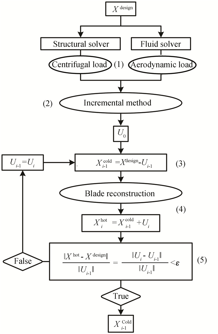
1 Pre-deformation Design Method for Blades 1.1 Pre-deformation ProcessThe purpose of pre-deformation is to compensate the amount of deformation of the blade under working condition in design stage, thus the desired configuration of the compressor blade under the specified working condition is ensured. Fig. 1 shows the iterative process of the pre-deformation design of a compressor blade.
|
Fig.1 Iterative process of blade pre-deformation |
The general idea is to pre-establish an assumed cold blade shape, calculate the assumed hot blade shape, which is deformed from the assumed cold blade shape, compare the deviation between the design blade shape and the assumed hot blade shape, and determine whether the deviation can meet precision requirements. If the deviation is satisfied, pre-deformation is completed. Otherwise, repeat the iterative process until convergence. Specific steps are as follows:
1) Structural analysis software and fluid analysis software were used to analyze the design blade shape Xdesign, which was known, and to obtain centrifugal load and aerodynamic load under design condition. The load conditions were divided equally, and the level of load increment was m (m= 10 was used). The generated equivalent node load condition was invoked by the load increment method.
2) The design blade shape Xdesign was loaded by load increment method, and the initial node displacement U0 was calculated.
3) Node displacement Ui-1 was set for the compensation dosage of pre-deformation (Ui-1=U0 was set for the first time iterative) and the new cold blade shape Xi-1cold=Xdesign-Ui-1 was calculated.
4) NEWTON-RAPHSON iterating method was used, blade reconstruction was carried out on cold blade Xi-1cold under design condition, node displacement Ui was obtained, and the relevant assumed hot blade shape was Xihot=Xi-1cold+Ui.
5) According to pre-established convergence coefficient ε (in this study ε=10-3), infinite norm was used to judge whether convergence was satisfied or not. Convergence criterion was
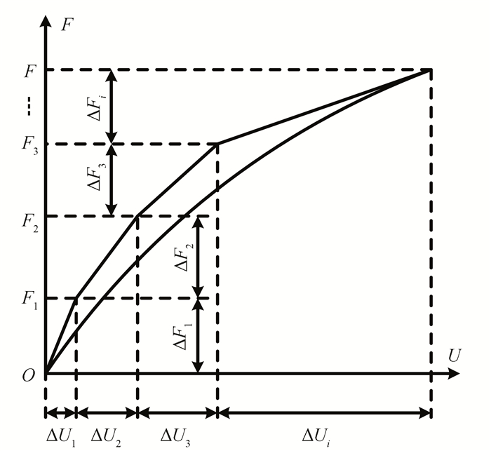
At the beginning of the pre-deformation design, a hypothetical cold blade shape is required as the initial condition. A good initial condition can improve the convergence speed of pre-deformation design. In this study, the load increment method was used to solve the initial deformation of the design blade of the compressor. The method is based on the basic concept of piecewise linear curve. The loading process diagram of load increment method is shown in Fig. 2. In order to deal with the non-linear relationship between the load F and the displacement U, load was divided into several micro-increments ΔFi according to certain rules. Then the blade was loaded step by step, and each level of load increment could be approximated as a linear process. There were no strict limits on the division of load increment. The magnitude of the load increment at all levels could be equal or not, so long as the sum of all the increments at all levels was equal to the full load, which was
|
Fig.2 Load incremental method |
The specific iterative steps of incremental method are as follows:
It was started with the design blade shape. The load increments from the first level to the last level were applied to the compressor blade step by step, and the displacement increment was obtained by solving the force balance equation ΔUi=[K(Ui-1)-1ΔFi. According to the current displacement results, the stiffness matrix of the blade was regenerated, and the next level of load increment ΔFi+1 was applied to solve the problem. Loading was repeated until the last level of load increment and the total deformation of the blade U was calculated.
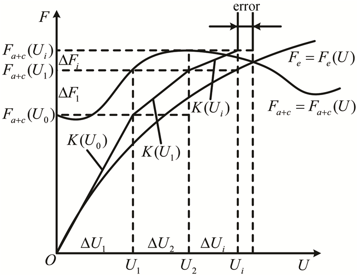
1.3 Reconstruction Method for BladeThe key to the success of blade reconstruction is to determine the deformation amount of the cold blade shape under operation condition, so as to confirm the actual configuration and aerodynamic performance of the compressor blade under the operation condition. The pressure load of the compressor blade has a strong nonlinear dependency relationship with blade configuration. Therefore, blade reconstruction is aimed at calculating deformation of blade under the non-conservative force. An iterative method of non-conservative force, which is used in this study, is introduced as follows. Rotating blades deform under the combined action of aerodynamic force Fa and centrifugal force Fc. These two kinds of forces are a function of node displacement U. According to stress analysis for the blade of compressor, at the final equilibrium state, resultant force Fa+c of the aerodynamic force and centrifugal force is equal to the elastic restoring force Fe of the blade, i.e. Fa+c(U)=Fe(U). In the analysis of the non-conservative force problem, it is not only necessary to solve the displacement of blade nodes, but also to solve the aerodynamic force and centrifugal force of the blade. The schematic diagram of the non-conservative iterative method is shown in Fig. 3. At the beginning of this process, Fa+c(U0) and K(U0) could be confirmed from the undeformed blade configuration. Then U1 was calculated. After the blade deformed, a new resultant force Fa+c(U1) was calculated to determine the unbalanced force ΔF1=Fa+c(U1)-Fa+c(U0) of the system. The variable quantity of displacement ΔU2 was confirmed according to stiffness matrix K(U1) obtained after deformation. By parity of reasoning, the variable quantity of displacement ΔUi was calculated by the unbalanced force ΔFi=Fa+c(Ui)-Fa+c(Ui-1) and stiffness matrix K(Ui), and the real solution was approximated by continuous iteration until the unbalanced force ΔFi was zero. As mentioned above, in solving the problem of non-conservative force, load force and stiffness matrix will be updated in every calculation step according to the variable quantity of node displacement in the last step. Hence, the nonlinear characteristics of load and stiffness matrix changing with variation configuration can be considered at the same time by using non-conservative iterative method.
|
Fig.3 The iterative method of non-conservative force (where Fa+c=Fa+c(U) is the combined force of aerodynamic and centrifugal loads, and Fe=Fe(U) is the elastic restoring force of the blade) |
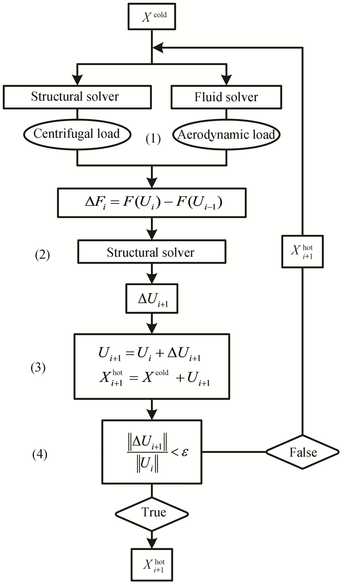
The blade reconstruction method adopted in this paper is shown in Fig. 4, and the solution process is as follows:
|
Fig.4 Iterative process of blade reconstruction |
1) It was started with the cold blade shape Xcold. Finite element analysis and flow field analysis were carried out using the cold blade shape, and centrifugal force and aerodynamic load F(Ui) were obtained. The unbalanced force of system ΔFi was the difference between F(Ui) and the load condition obtained at the last iteration F(Ui-1). For the first calculation, the stress load of Xcold was set as the unbalanced force of the system.
2) Unbalanced force of the system ΔFi was added onto the blade shape to calculate the incremental quantity of displacement ΔUi+1 by structural analysis.
3) Node coordinate of the assumed hot blade shape Xi+1hot=Xcold+Ui+1 was calculated. For the first calculation, U1=ΔU1 was set.
4) According to the pre-established convergence coefficient ε(=10-3), infinite norm was used to judge the convergence, and the convergence criterion was
In this study, the pre-deformation design and blade reconstruction calculation of Stage 37 rotor blades of the transonic compressor were carried out.
The design speed of Stage 37 was 17188.7 r/min, the tip clearance of the rotor blade was 0.356 mm, the total pressure ratio was 2.050, the adiabatic efficiency was 0.842, the blade material was Maraging 200 whose elastic modulus was 210 GPa, Poisson's ratio was 0.3, and the density was 8000 kg/m3. The specific design parameters and test data can be seen in Refs. [17-18]. Blade profile data given by Ref. [17] was set as the design blade shape, and peak efficiency point at selected design speed was set as the design condition. The Stage 37 rotor blade was pre-deformed according to the stress condition of the design point. After obtaining the cold blade shape, the blade reconstruction calculation was carried out under the off-design condition. It must be noted that the stator blade was rigid enough to resist deformation. The rotor blade was the only concern when blade shape was converted, and pre-deformation and reconstruction calculation were not performed on the stator blades.
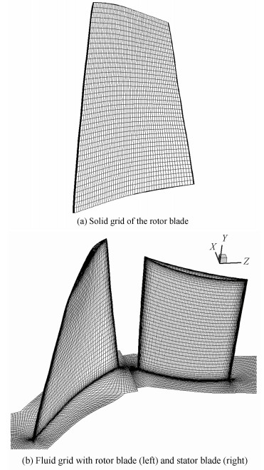
Fig. 5 shows the blade solid grid and fluid grid of stage. Static deformation of the moving blade was calculated by using ANSYS. A hexahedron grid was used in the finite element model of the moving blade, and the total number of solid grids was 11808. Fixed branch boundary was adopted in blade root. An O4H topological structure was adopted in fluid grid, and the total number of grids was 1339852. CFX was used in the steady numerical simulation of fluid domain, and the k-ε turbulence model was selected. The blending plane method was used in dealing with the junction of dynamic and static domain. The inlet total pressure and inlet total temperature of the boundary conditions were set, and the flow field results of different working conditions were adjusted by changing the backpressure of the outlet. The transfer of solid deformation to the flow field grid was realized by means of dynamic mesh technique. In order to ensure the quality of fluid grid, the grids of zone on the moving blade near to casing were set as rotating surface.
|
Fig.5 Computational grid |
3 Results Analysis
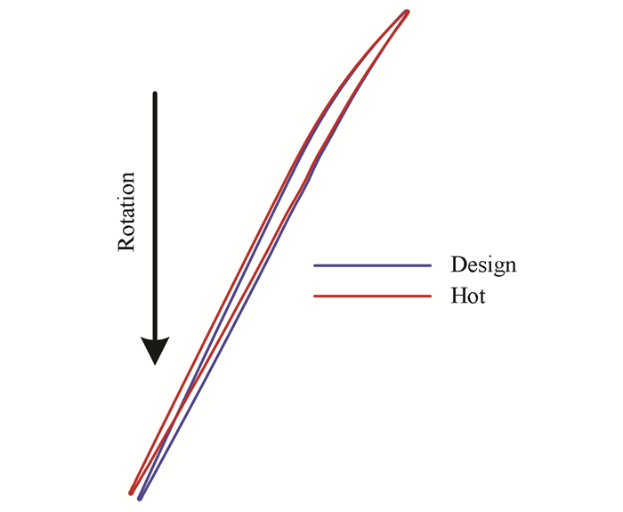
To verify the reliability of the proposed reconstruction algorithm, the blade shape given by Ref.[17] was set as the design blade shape. Reconstruction of the blade shape was carried out at each design working condition point, and the reconstructed hot blade shape was used to calculate flow field. The comparison between the design blade shape and its hot blade shape is shown in Fig. 6, where "Hot" represents the hot blade shape, and "Design" represents the design blade shape. The geometry of the design blade does not change under all working conditions. As shown in Fig. 6, untwisting deformation of the hot blade occurred in a clockwise motion under the action of aerodynamic force and centrifugal force. The deformation amount was gradually increased from the trailing edge to leading edge.
|
Fig.6 Comparison of cold and hot blade at blade tip |
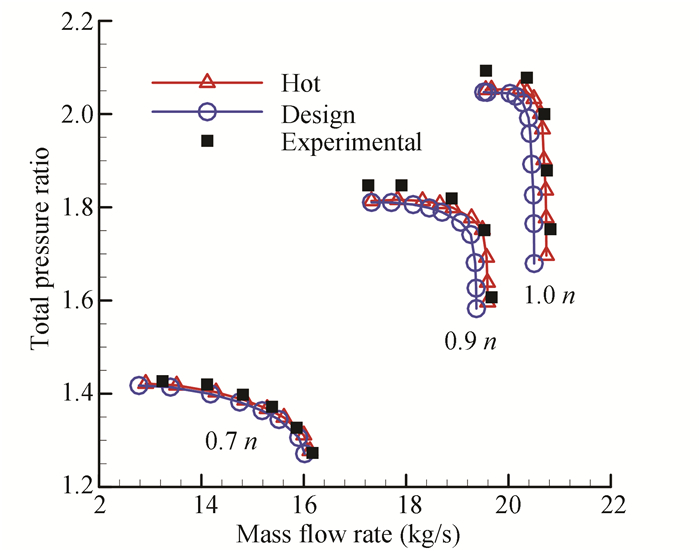
Comparison of the characteristic curve of total pressure ratio between the design blade shape and the hot blade shape was carried out, which is shown in Fig. 7. n represents the design speed in this figure. As is illustrated, the hot characteristic curve obtained by reconstruction calculation moves along the direction of large mass flow rate relative to the design characteristic curve, and the total pressure ratio increases. The difference of total pressure characteristics increases with the rotational speed. Hot choke flow rate at 70% design speed 16.12 kg/s is 0.62% higher than design choke flow rate (16.02 kg/s). At 90% design speed, the hot choke flow rate 19.59 kg/s is 1.14% higher than design choke flow rate (19.37 kg/s). At the design speed, hot choke flow rate 20.74 kg/s is 1.17% higher than design choke flow rate (20.50 kg/s). In general, the blade reconstruction algorithm in which deformation of blade was considered obtained a better agreement between the prediction (Hot) and test results, and the reliability and validity of the reconstruction method were verified.
|
Fig.7 Comparison of CFD results of total pressure ratio of cold and hot designs with test |
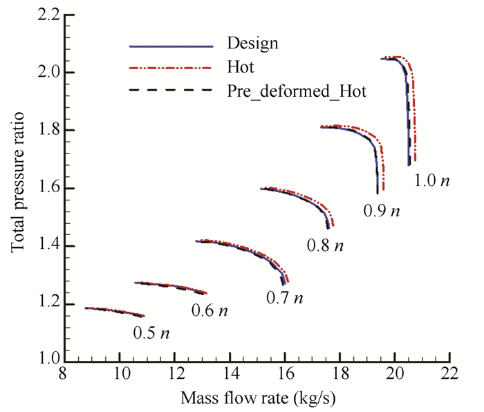
The proposed method can be used to obtain desired cold blade geometry that achieves the desired hot performance. Fig. 8 shows the results of its application to the same rotor of Stage 37, where the total pressure ratio curve of "Design" shows the desired performance, the curve of "Hot" indicates the performance will be under real hot condition if the blade is designed under cold condition and the deformation caused by the hot condition is not considered, and that of "Pre_deformed_Hot" gives the results when the deformation is taken into consideration under the stage design condition at blade design stage. The untwisting deformation of the blade increased the flow of the compressor and aerodynamic load under the hot condition. The blade with the compensation of the pre-deformation was designed to obtain the hot blade shape that approximate to the optimum aerodynamic configuration under the design working condition. As shown in Fig. 8, the performance of the pre-deformation obtained by reconstruction calculation moved to smaller mass flow rates, and gave a better match to the desired intention, despite that the design condition was only employed in the pre-deformation correction. A good agreement with the design characteristic curve at all the speeds was achieved which shows the validity of the pre-deformation method. The results additionally show that the centrifugal force played a leading role in the deformation of the blade.
|
Fig.8 Total pressure ratio characteristic curves of pre-deformed blade in comparison with design intention |
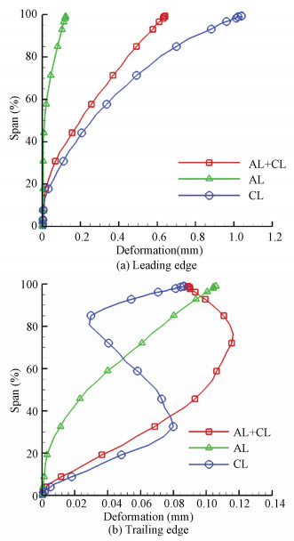
Fig. 9 shows the deformation along the blade development direction of the front and tail edge of the cold blade under the three loading conditions of aerodynamic load (AL), centrifugal load (CL), and combined aerodynamic load (AL + CL). The deformation is relative to the design blade. It can be seen from Fig. 9 that different load conditions have obvious influence on the law of the spanwise distribution of the compensation deformation. Compared with the case that considers two loads (AL + CL) at the same time (the compensation of leading edge point at the top of blade is 0.64 mm), when considering aerodynamic load (AL) alone, the compensation of leading edge pre-deformation is insufficient (the compensation of leading edge point at the top of blade is 0.12 mm); when considering centrifugal load (CL) alone, the compensation of leading edge pre-deformation is excessive (the compensation of leading edge point at the top of blade is 1.04 mm).
|
Fig.9 Radial distributions of the deformation at blade leading and trailing edges under different load conditions |
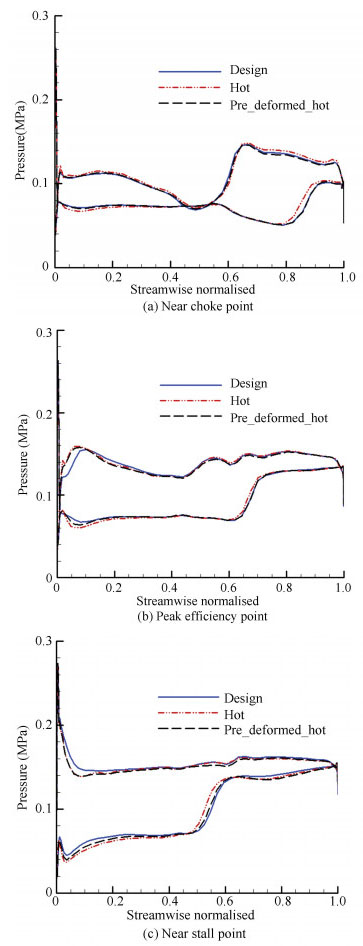
Fig. 10 shows the static pressure distribution of the blade surface at 99% blade span under the design rotational speed. As shown in Fig. 10, when aeroelastic deformation is considered, the position of suction surface shock wave of the hot blade shape moves towards the leading edge relative to the design blade shape. The axial dimension of separation zone caused by the disturbance of boundary layer by the shock wave increases. The load of leading edge increases at the same time. Due to the untwist deformation of the blade, under all the three flow conditions, the blade tip was in the working state of the positive attack angle, and the aerodynamic load increased, which is not conducive to the stable operation of the compressor. The hot state static pressure distribution of the pre-deformed blade was closer to that of the design blade under the three typical operating conditions, and the extent of separation zone, was weakened. The stability of the flow was enhanced after the suction surface shock wave, which is consistent with the more negative slope of the pressure ratio curve displayed.
|
Fig.10 Comparison of pressure distribution at 99% span and design speed |
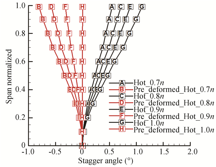
In order to investigate the law of twist deformation for the cold and hot state blade shape, the untwist angle of the blade is introduced. It is defined as the difference between the installation angle of the blade under working condition and the installation angle of the design blade at a specified blade span section. The installation angle in this study is the acute angle between the blade chord and the tangential direction. The reverse twist angle is positive, corresponding to the blade to increase the flow angle and vice versa. If the untwist angle positively corresponds to the incoming flow, the attack angle will increase. Fig. 11 shows the span wise distribution of the untwist angle at peak efficiency point for different rotational speeds. As shown in Fig. 11, a working blade (labelled Hot) in design blade shape with stagger angle equal to zero generates a positive untwist deformation. Moreover, the untwist deformation increases with blade rotational speed and blade span. The untwist angle of the blade is positive along the whole blade span, meaning that the whole blade span is in the positive attack angle.
|
Fig.11 Radial distributions of the untwist angle at different speeds under peak efficiency condition |
At 70%, 80%, 90%, and 100% design speed, the maximum untwist angle of the working blade was 0.5°, 0.7°, 0.9°, and 1.1°, respectively. After the pre-deformation (labelled Pre-deformed_Hot in Fig. 11) and at the same rotational speeds, the maximum untwist angle of blade was -0.8°, -0.6°, -0.3°, and 0°, respectively. Observed from the blade tip to the blade root, the blade was twisted counterclockwise by pre-deformation design. Hot deformation under the design operating condition was compensated, which made the actual configuration close to the ideal configuration at the design point of the blade and reduced positive attack angle and flow separation loss. However, at speeds lower than the design speed, the untwist angle was negative along the whole blade span. This is because the centrifugal force and aerodynamic force both reduced with blade speed, and the actual untwist deformation was not sufficient to fully balance the pre-deformation. The untwist angle at low rotational speed was negative, which decreased the actual flow area. At the same time, the attack angle of blade was negative and aerodynamic load reduced, causing a decrease of the choke flow rate and pressure ratio of the pre-deformation blade under the low rotational speeds. The untwist angles at 99% blade span vs. total pressure ratios under different working conditions are shown in Fig. 12. As is illustrated, if the design blade shape is directly used, the compressor blade shape will deviate from the ideal geometrical configuration and the blade will be in the positive attack angle state when the compressor is actually running. The pre-deformation design ensures that the actual blade shape is consistent with the intended design blade shape at the design speed. However, due to the constant compensation of pre-deformation, it will overcompensate at speeds lower than the design speed. Therefore, the untwist angle of the blade at low speeds is inevitably negative. The increase of rotational speed and pressure ratio both increase the untwist angle of the blade, showing that the directions of twist deformation on blade affected by centrifugal force and aerodynamic force are the same.

|
Fig.12 Variation of the untwist angle at 99% span with total pressure ratio at different speeds |
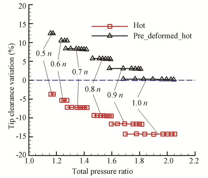
The blade tip clearance has significant influence on the stable operation and aerodynamic performance of the compressor. Excessive clearance will cause an increase in leakage and loss and a decrease in efficiency, while a smaller clearance may lead to rubbing of the blade and casing, threatening the safe operation of the unit. The variable quantities of blade tip clearance relative to design value under different working conditions are shown in Fig. 13. As is illustrated, at the same rotational speed, the tip clearance was not significantly changed with the increase of aerodynamic load. The change of clearance was mainly affected by the rotational speed. Stretching effect of centrifugal force was enhanced with the increase of rotational speed and the blade tip clearance decreased accordingly. For the hot blade shape of the design blade shape, the blade tip clearance decreased by 3.7% at 50% design rotational speed and by 14.3% at the design speed. Although the decrease of blade tip clearance was beneficial to reduce the leakage loss, it increased the possibility of rubbing of blade tip and casing. Sufficient safety margin of the clearance should be considered at design stage. The blade tip clearance of the pre-deformation blade decreased by only 0.2% at the design rotational speed, which reduced the deviation between the blade tip clearance and the design value effectively and provided guarantee for the safe operation of the compressor. But under low-speed working conditions, the centrifugal force had a weaker stretching effect, and the tensile deformation of the blade was reduced. Therefore, the blade tip clearances relative to design values were increased under low-speed working conditions. At 50% design speed, the blade tip clearance was increased by 12.4%. As has been pointed out, the choke flow rate and pressure ratio of pre-deformed blade at low-speeds would be reduced. The reason is that not only the untwist deformation was insufficient, which decreased the throat area and the attack angle of incoming flow, but also the increase of blade tip clearance increased tip leakage loss and flow area of blade tip.
|
Fig.13 Variation of the tip clearance size with total pressure ratio at different speeds |
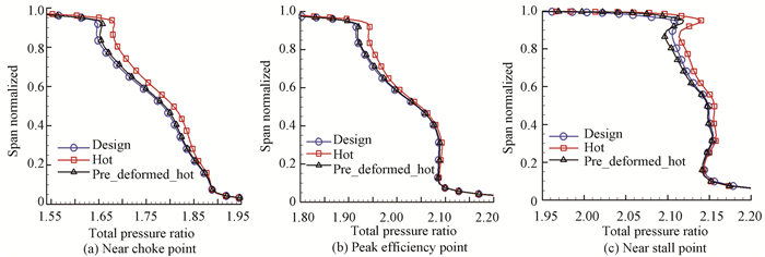
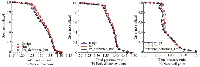
Figs. 14-15 show the radial distributions of total pressure ratio of moving blade outlet at design speed and 70% design speed, respectively. From Figs. 14-15, total pressure ratio of the hot blade shapes of the design blade increased relative to the rigid design configuration and the pre-deformed hot blade under both the high-speed and the low-speed conditions, especially at high blade spans. This is consistent with the increase of the attack angle of the blade, which resulted in an increase of aerodynamic load. At design rotational speed, the hot pressure ratio distribution of the pre-deformed blade was in good agreement with that of the design blade, while at 70% design speed, it was lower than that of the design blade. It proves that under low-speed condition, aerodynamic force and centrifugal force are too small to balance the compensated deformation of pre-deformation at design speed, which under low-speed condition, leads to the blade in negative attack angle condition and a decrease in aerodynamic load and the total pressure ratio.
|
Fig.14 Radial distributions of the rotor total pressure ratio at design speed |
|
Fig.15 Radial distributions of the rotor total pressure ratio at 70% design speed |
4 Conclusions
A new pre-deformation design method for rotor blade of compressors is presented based on Newton-Raphson method and load increment method. Pre-deformation design was carried out on Stage 37 rotor blade. A non-linear reconstruction method was applied to obtain the hot blade shape and its aerodynamic performance of pre-deformed blade under off-design condition. The differences of aerodynamic and structural parameters between hot and cold blade shape were compared and analyzed. The main conclusions of the study are as follows:
1) The pre-deformation method for rotor blade of compressor is effective and can ensure ideal blade shape under design condition.
2) Referring to design operating condition, the pre-deformation design could compensate the untwist deformation and tensile deformation. Flow instabilities caused by increase of attack angle of flow after untwist deformation was alleviated. Untwist angle of the pre-deformed blade under working condition was 0°. The pre-deformation design could also fully maintain the design blade tip clearance. The blade tip clearance of the pre-deformed blade decreased by only 0.2% at the design rotational speed.
3) At 80%, 90%, and 100% design speed, the aerodynamic characteristics of the pre-deformation blades were in good agreement with the rigid design blade shape. However, at lower speeds, the choke flow and pressure ratio of the compressor relative to the rigid design were reduced.
| [1] |
Liu G L. A new generation of inverse shape design problem in aerodynamics and aerothermoelasticity: concepts, theory and methods. Aircraft Engineering and Aerospace Technology, 2000, 72(4): 334-344. DOI:10.1108/00022660010340141 (  0) 0) |
| [2] |
Zheng Y, Tian X, Yang H. Impact of blade deflection on aerodynamic performance of a transonic fan. Journal of Aerospace Power, 2011, 26(7): 1621-1627. (in Chinese) DOI:10.13224/j.cnki.jasp.2011.07028 (  0) 0) |
| [3] |
Hazby H, Woods I, Casey M, et al. Effects of blade deformation on the performance of a high flow coefficient mixed flow impeller. Journal of Turbomachinery, 2015, 137(12): 121005-121005-9. DOI:10.1115/1.4031356 (  0) 0) |
| [4] |
Vahdati M, Simpson G, Imregun M. Unsteady flow and aeroelasticity behavior of aeroengine core compressors during rotating stall and surge. Journal of Turbomachinery, 2008, 130(3): 538-544. DOI:10.1115/1.2777188 (  0) 0) |
| [5] |
Yamada K, Furukawa M, Nakakido S, et al. Large-scale des analysis of unsteady flow field in a multi-stage axial flow compressor at off-design condition using K computer. ASME Turbo Expo 2015: Turbine Technical Conference and Exposition. New York: ASEM, 2015. GT2015-42648-V02CT44A011. DOI: 10.1115/GT2015-42648.
(  0) 0) |
| [6] |
Jiang B, Zheng Q, Wang S T. Research on the aerodynamic design of transonic fan and unsteady flow structure. Journal of Engineering Thermophysics, 2013, 34(12): 2248-2252. (in Chinese) (  0) 0) |
| [7] |
Paul L M. Vibration of Axial Turbomachinery Blades: Measurement and Fluid-structure Interactions. Notre Dame, Indiana: University of Notre Dame, 2012.
(  0) 0) |
| [8] |
Gill J D, Capece V. Experimental investigation of flutter in a single stage unshrouded axial-flow fan. Proceedings of the 42nd AIAA Aerospace Sciences Meeting and Exhibit. Reston, VA: AIAA, 2004. DOI: 10.2514/6.2004-686.
(  0) 0) |
| [9] |
Ohtsuka M. Untwist of rotating blades. Journal of Engineering for Gas Turbines and Power, 1975, 97(2): 180-187. DOI:10.1115/1.3445954 (  0) 0) |
| [10] |
Liu G L. The generalized untwist problem of rotating blades: a coupled aeroelastic formulation. International Journal of Turbo and Jet Engines, 1995, 12(2): 109-117. DOI:10.1515/TJJ.1995.12.2.109 (  0) 0) |
| [11] |
Mahajan A J, Stefko G L. An iterative multidisciplinary analysis for rotor blade shape determination. Proceedings of the 29th Joint Propulsion Conference and Exhibit. Reston, VA: AIAA. AIAA-93-2085. DOI: 10.2514/6.1993-2085.
(  0) 0) |
| [12] |
Timon V P, Corral R. A study on the effects of geometric non linearities on the un-running transformation of compressor blades. ASME Turbo Expo 2014: Turbine Technical Conference and Exposition. New York: ASME, 2014. ASME-GT2014-25638-V07BT33A008. DOI: 10.1115/GT2014-25638
(  0) 0) |
| [13] |
Wang S B, Li S B, Song X Z. Investigations on static aeroelastic problems of transonic fans based on fluid-structure interaction method. Proceedings of the Institution of Mechanical Engineers, Part A: Journal of Power and Energy, 2016, 230(7): 685-695. DOI:10.1177/0957650916668456 (  0) 0) |
| [14] |
Mao J, Yang L G, Xi Y H. Numeric analysis of the pneumatic elasticity of large axial-flow fan blade. Journal of Mechanical Engineering, 2009, 45(11): 133-139. (in Chinese) DOI:10.3901/JME.2009.11.133 (  0) 0) |
| [15] |
Zheng Y, Wang B, Yang H. Numerical study on blade un-running design of a transonic fan. Journal of Mechanical Engineering, 2013, 49(5): 147-153. (in Chinese) DOI:10.3901/JME.2013.05.147 (  0) 0) |
| [16] |
Zheng Y, Wang B, Yang H, et al. Blade untwist influencing factors of a transonic fan. Gas Turbine Experiment and Research, 2013, 26(5): 7-11. (in Chinese) (  0) 0) |
| [17] |
Reid L, Moore R D. Design and Overall Performance of Four Highly Loaded, High-speed Inlet Stages for an Advanced High-pressure-ratio Core Compressor. https://ntrs.nasa.gov/archive/nasa/casi.ntrs.nasa.gov/19780025165.pdf, 2020-02-25.
(  0) 0) |
| [18] |
Dunham J. CFD Validation for Propulsion System Components. Hull: Canada Communication Group Inc., 1998.
(  0) 0) |
 2021, Vol. 28


