2. Hubei Key Laboratory of Engineering Structural Analysis and Safety Assessment, Wuhan 430074, China
The flow mechanism of fluid inside the combustion chamber of solid rocket motor (SRM) is complex, and numerous calculation models were constructed by many researchers. Such as Sachdev et al.[1-3]used the multiphase flow model with adaptive mesh to simulate the core flow in the internal ballistics of SRM in axial symmetry flowfield. Havlucu et al.[4] used the combustion coupled with the regressive boundary to study the two-dimension (2D) reactive flow in an end burning lab-scale motor. Han et al.[5] used the integrated fluid-structure method to examine the nonlinear feedback interaction between fluid, structure, and burning module. Due to the computational cost and complexity, the burning surface deformation was disregarded by many researchers. However, the internal ballistic performance curve of SRM is significantly affected by the burning surface evolution. Gueyffier et al.[6-7] introduced the spectral method to simulate the three-dimension (3D) flowfield with dynamic grain regression, but they focused mostly on designing a set of algorithms to track the propagating surfaces. Similar work like Refs. [8-9] also studied the grain regressing in detail. Computational cost and simulation results of these researches are barely satisfactory, so a more accurate and fast method for internal ballistic flow simulation is demanded urgently.
In 1997, Blomshield et al.[10] employed the quasi-one-dimensioned (Q1D) flowfield to study the nonlinear (pulsed) instability of a motor which was believed related to its linear stability. They presented the pressure-couple method to validate the linear instability response of the flowfield which has a good agreement with experiment data. Then many researchers have devoted to studying the Q1D internal flowfield of SRM. In 2007, Willcox et al.[11-12] developed a code named Rocballist which first employed the minimum distance function (MDF) to calculate the three-dimensioned (3D) grain, and coupled with the zero- or one-dimensioned (0D or 1D) flowfield to simulate the internal ballistics of SRM. After that, the Q1D internal flowfield simulation of SRM entered a new era in the following decade. Cavallini et al.[13-17]presented a numerical tool named SPINBALL which the basic function of their code was just like the Rocballist. Unlike Rocballist, they used the level-set method instead of MDF to calculate the 3D grain surface, and some extra functions such as the 1D acoustic analysis and nozzle erosion were added. A similar numerical tool named SPPMEF was also developed by Terzic et al.[18]
According to these references, it is found that the works which simulated the entire flowfield always ignores the burning surface regressing or those which considers the grain evolution always neglects the fluid flow in nozzle. In fact, the fuel gas velocity of nozzle exit directly affects the thrust of the SRM. In this study, a method is presented to simulate the entire flowfield from the head of the chamber to the exit of the nozzle coupled with grain regressing.
This study is devoted to propose and present an approach to solve the the Q1D internal flowfield of SRM. This approach is the total variation diminishing (TVD) MacCormack scheme[19-21], which is simpler than the AXS solver[22]of Rocballist and is convenient to optimize, and couples to 3D burning surface solved by level-set method[23]. In Section 1, the governing equations of flowfield and burning surface regression is presented, and the numerical discrete schemes of TVD-MacCormack and level-set methods are introduced in Section 2. Section 3 shows some simulation results of this code and two main module test of this code. Finally, Section 4 provides conclusions.
1 Governing EquationsWhen the performance of internal ballistics is studied, the radial and azimuthal variations parameters are always negligible. So the Q1D flow is used to replace the 3D flow to save computational cost. In this section, the governing equations of Q1D internal flow (from the head of the burn chamber to the exit of the nozzle) and 3D level set method which is used to solve the burning surface regression are shown.
1.1 One-Dimensional Euler Equations with Source TermsThe conservation forms of equations are presented as follows. The continuity equation is
| $ \frac{\partial(\rho A)}{\partial t}+\frac{\partial(\rho A V)}{\partial x}=\dot{m} $ | (1) |
where
| $ \dot{m}= \begin{cases}\rho_{p} r_{b} \frac{\partial A_{b}}{\partial x}, & \text { in chamber } \\ 0, & \text { in nozzle }\end{cases} $ |
The momentum equation is
| $ \frac{\partial(\rho V A)}{\partial t}+\frac{\partial\left(\rho V^{2} A\right)}{\partial x}=-A \frac{\partial p}{\partial x}+F_{b} $ | (2) |
where Fb is the body force.
The energy equation is
| $ \frac{\partial}{\partial t}\left[\rho A\left(e+\frac{V^{2}}{2}\right)\right]+\frac{\partial}{\partial x}\left[\rho A V\left(h+\frac{V^{2}}{2}\right)\right]=\dot{m} h-\dot{q} $ | (3) |
Since for ideal gas,
| $ p=\rho R T, c_{p}-c_{v}=R, c_{p} / c_{v}=\gamma, e=c_{v} T $ |
The governing equations above could be abbreviated as a conservation form:
| $ \frac{\partial \boldsymbol{U}}{\partial \mathrm{t}}+\frac{\partial \boldsymbol{F}}{\partial _\mathrm{X}}=\boldsymbol{J} $ | (4) |
where
| $ \boldsymbol{U}=\left[\begin{array}{lll} \rho A & \rho A V & \rho A\left(c_{v} T+\frac{V^{2}}{2}\right) \end{array}\right]^{\mathrm{T}} $ |
| $ \boldsymbol{F}=\left[\begin{array}{lll} \rho A V & \rho A V^{2}+A p & \rho V A\left(c_{p} T+\frac{V^{2}}{2}\right) \end{array}\right] $ |
| $ \boldsymbol{J}=\left[\begin{array}{c} \dot{m} \\ (\gamma-1) \rho c_{v} T \frac{\partial A}{\partial x}+\rho A g \\ c_{p} T_{0} \dot{m}-\dot{q} \end{array}\right] $ |
The level-set method which is good at computing and analyzing the motion of an interface in two or three dimensions was used to solve the burning surface in real-time. In Eq.(5), ϕ is defined as the signed distance function which is used to distinguish the fluid in two-phase flow. ϕ=0 means it is the interface, ϕ>0 represents one fluid, and ϕ < 0 represents the other one. During solving the level-set equations, reinitializing the function periodically so as to reduce the numerical errors caused by both steepening and flattening effects is necessary, so that it can construct the interface accurately [23].
Since the solid propellant grain evolution is regressing in the normal direction, the motion in the normal direction level-set function[23] was used to evaluate
| $ \phi_{t}+a|\nabla \phi|=0 $ | (5) |
where a is the normal velocity. When a>0, the interface moves in the normal direction, while when a < 0, the interface moves in the opposite direction. In addition,
| $ |\nabla \phi|=\sqrt{\phi_{x}^{2}+\phi_{y}^{2}+\phi_{z}^{2}} $ |
where,
| $ \phi= \begin{cases}-d, & \text { for } x \in \varOmega_{\text {propellat }} \\ 0, & \text { for } x \in \varGamma_{\text {sf }} \\ d, & \text { for } x \in \varOmega_{\text {gas }}\end{cases} $ |
The reinitialization equation refers to the work of Sussman and Fatemi[24]. This equation uses a nine-point quadrature formula to evaluate the integrals in two spatial dimensions:
| $ \phi_{t}+S\left(\phi_{0}\right)(|\nabla \phi-1|)=\lambda \hat{\delta}(\phi) $ | (6) |
where S(ϕ0) is the sign function as follows:
| $ S\left(\phi_{0}\right)= \begin{cases}1, & \text { in } \varOmega^{+} \\ 0, & \text { in } \varGamma_{\mathrm{sf}} \\ -1, & \text { in } \varOmega^{-}\end{cases} $ |
and
| $ \lambda_{i, j}=-\frac{\int_{\varOmega_{i, j}} \delta(\phi)\left(\frac{\phi^{n+1}-\phi^{n}}{\Delta t}\right) \mathrm{d} \vec{x}}{\int_{\varOmega_{i, j}} \delta^{2}(\phi)|\nabla \phi| \mathrm{d} \vec{x}} $ |
| $ \begin{aligned} \hat{\delta}(\phi)=& \delta(\phi)|\nabla \phi|=\\ & H^{\prime}(\phi(\vec{x})) \nabla \phi(\vec{x}) \cdot \frac{\nabla \phi(\vec{x})}{|\nabla \phi(\vec{x})|} \end{aligned} $ |
where H is the Heaviside function.
2 Numerical ProcedureIn this section, the numerical methods which discretized the Euler equations and the level-set equation are presented.
2.1 TVD-MacCormack SchemeThis scheme was used to discrete the Q1D flow.
The predictor step is
| $ U_{i}^{p}=U_{i}^{t}-\frac{\Delta t}{\Delta x}\left(F_{i}-F_{i-1}\right)+\Delta t J_{i} $ | (7) |
The corrector step is
| $ U_{i}^{c}=U_{i}^{t}-\frac{\Delta t}{\Delta x}\left(F_{i+1}^{p}-F_{i}^{p}\right)+\Delta t J_{i} $ | (8) |
The TVD scheme is
| $ \begin{gathered} U_{i}^{t+\Delta t}=\frac{U_{i}^{p}+U_{i}^{c}}{2}+\left[K\left(r_{i}^{+}\right)+K\left(r_{i+1}^{-}\right)\right] \Delta U_{i+\frac{1}{2}}^{t}- \\ {\left[K\left(r_{i-1}^{+}\right)+K\left(r_{i}^{-}\right)\right] \Delta U_{i-\frac{1}{2}}^{t}} \end{gathered} $ | (9) |
where the subscript i is the specific grid point xi, and these formulas are
| $ \Delta U_{i+\frac{1}{2}}^{t}=U_{i+1}^{t}-U_{i}^{t}, \Delta U_{i-\frac{1}{2}}^{t}=U_{i}^{t}-U_{i-1}^{t} $ |
| $ K^{\pm}\left(r^{\pm}\right)=0.5 C(\nu)\left[1-\phi\left(r^{\pm}\right)\right] $ |
| $ r_{i}^{+}=\frac{\left(\varDelta U_{i-\frac{1}{2}}^{t}, \varDelta U_{i+\frac{1}{2}}^{t}\right)}{\left(\Delta U_{i+\frac{1}{2}}^{t}, \Delta U_{i+\frac{1}{2}}^{t}\right)}=\frac{\left(U_{i}^{t}-U_{i-1}^{t}, U_{i+1}^{t}-U_{i}^{t}\right)}{\left(U_{i+1}^{t}-U_{i}^{t}, U_{i+1}^{t}-U_{i}^{t}\right)} $ |
| $ r_{i}^{-}=\frac{\left(\Delta U_{i-\frac{1}{2}}^{t}, \Delta U_{i+\frac{1}{2}}^{t}\right)}{\left(\Delta U_{i-\frac{1}{2}}^{t}, \varDelta U_{i-\frac{1}{2}}^{t}\right)}=\frac{\left(U_{i}^{t}-U_{i-1}^{t}, U_{i+1}^{t}-U_{i}^{t}\right)}{\left(U_{i}^{t}-U_{i-1}^{t}, U_{i}^{t}-U_{i-1}^{t}\right)} $ |
| $ \phi(r)=\max (0, \min (2 r, 1)) $ |
| $ \nu=\max \limits_{j}\left|\lambda_{j}\right| \frac{\Delta t}{\Delta x} $ |
where λj is the eigenvalue of the Jacobian matrix U .
| $ C(\nu)= \begin{cases}\nu(1-\nu), & \nu \leqslant 0.5 \\ 0.25, & \nu>0.5\end{cases} $ |
The non-slip and adiabatic boundary conditions were used in the head of the grain:
| $ \left\{\begin{array}{l} \left(U_{1}\right)_{1}=\left(U_{1}\right)_{2} \\ \left(U_{2}\right)_{1}=0 \\ \left(U_{3}\right)_{1}=\left[\frac{\left(U_{3}\right)_{2}}{\left(U_{1}\right)_{2}}-\frac{\left(U_{2}\right)_{2}^{2}}{2\left(U_{1}\right)_{2}^{2}}+\frac{\left(U_{2}\right)_{1}^{2}}{2\left(U_{1}\right)_{1}^{2}}\right]\left(U_{1}\right)_{1} \end{array}\right. $ | (10) |
When the outlet of nozzle is subsonic (Ma < 1), the boundary conditions are
| $ \left\{\begin{array}{l} \left(U_{1}\right)_{N}=\left(U_{1}\right)_{N-1} \\ \left(U_{2}\right)_{N}=\left(U_{2}\right)_{N-1} \\ \left(U_{3}\right)_{N}=\frac{A_{N} p_{a}}{\gamma-1}+\frac{\left(U_{2}^{2}\right)_{N}}{2\left(U_{1}\right)_{N}} \end{array}\right. $ | (11) |
When Ma≥1, the boundary conditions are
| $ \left\{\begin{array}{l} \left(U_{1}\right)_{N}=\left(U_{1}\right)_{N-1} \\ \left(U_{2}\right)_{N}=\left(U_{2}\right)_{N-1} \\ \left(U_{3}\right)_{N}=\left(U_{3}\right)_{N-1} \end{array}\right. $ | (12) |
Some literature reported that the level-set method coupled to the flow solver may induce mass non-conservation when discretizing the advection or reinitialization equation because mass conservation is not embedded in the formulation. However, Solomenko et al.[25] focused on this question and conducted quantitative research. Their results showed that the combination of total variation-diminishing second-order Runge-Kutta method (TVD RK2)[26] for temporal discretization and a fifth-order weighted-essentially-non-oscillatory (WENO5)[23, 25] for spatial discretization can improve the mass conservation.
The second-order accurate TVD RK scheme was used to discrete the temporal derivatives and the WENO5 was used to discrete the spatial derivatives.
The TVD RK2 is as follows:
| $ \left\{\begin{array}{l} \frac{\phi^{n+1}-\phi^{n}}{\varDelta t}+\vec{V}{}^{n} \cdot \nabla \phi^{n}=0 \\ \frac{\phi^{n+2}-\phi^{n+1}}{\varDelta t}+\vec{V}{}^{n+1} \cdot \nabla \phi^{n+1}=0 \\ \phi^{n}=\frac{1}{2} \phi^{n}+\frac{1}{2} \phi^{n+2} \end{array}\right. $ | (13) |
The WNEO5 is as follows:
| $ \begin{aligned} D_{x}^{\pm} \phi_{i}&=\omega_{i}^{(1)} D_{x}^{\pm} \phi_{i}^{(1)}+ \\ &\omega_{i}^{(2)} D_{x}^{\pm} \phi_{i}^{(2)}+\omega_{i}^{(3)} D_{x}^{\pm} \phi_{i}^{(3)} \end{aligned} $ | (14) |
where
| $ \left\{\begin{array}{l} D_{x}^{\pm} \phi_{i}^{(1)}=\frac{1}{3} c_{1}^{\pm}-\frac{7}{6} c_{2}^{\pm}+\frac{11}{6} c_{3}^{\pm} \\ D_{x}^{\pm} \phi_{i}^{(2)}=-\frac{1}{6} c_{2}^{\pm}+\frac{5}{6} c_{3}^{\pm}+\frac{1}{3} c_{4}^{\pm} \\ D_{x}^{\pm} \phi_{i}^{(3)}=\frac{1}{3} c_{3}^{\pm}+\frac{5}{6} c_{4}^{\pm}-\frac{1}{6} c_{5}^{\pm} \end{array}\right. $ |
These coefficient are
| $ \left\{\begin{array}{l} c_{p}^{-}=\frac{\phi_{i-2+(p-1)}-\phi_{i-3+(p-1)}}{h}\\ c_{p}^{+}=\frac{\phi_{i+3-(p-1)}-\phi_{i+2-(p-1)}}{h} \end{array}, p \in[[1,5]] \right. $ |
Weights are computed as
| $ \omega^{(p) \pm}=\frac{\alpha_{i}^{(p) \pm}}{\alpha_{i}^{(1) \pm}+\alpha_{i}^{(2) \pm}+\alpha_{i}^{(3) \pm}}, p \in[[1,3]] $ |
It is defined that
| $ \left\{\begin{array}{l} \alpha_{i}^{(1) \pm}=\frac{1}{10}\left(\frac{1}{\varepsilon+s^{(1)}}\right)^{2} \\ \alpha_{i}^{(2) \pm}=\frac{3}{5}\left(\frac{1}{\varepsilon+s^{(2)}}\right)^{2} \\ \alpha_{i}^{(3) \pm}=\frac{3}{10}\left(\frac{1}{\varepsilon+s^{(3)}}\right)^{2} \end{array}\right. $ |
where ε=10-6max{c12, c22, c32, c42, c52}+10-99
At last, the smoothness indicators are
| $ \left\{\begin{array}{l} s^{(1)}=\frac{13}{12}\left(c_{1}^{\pm}-2 c_{2}^{\pm}+c_{3}^{\pm}\right)+\frac{1}{4}\left(c_{1}^{\pm}-4 c_{2}^{\pm}+3 c_{3}^{\pm}\right)^{2} \\ s^{(2)}=\frac{13}{12}\left(c_{2}^{\pm}-2 c_{3}^{\pm}+c_{4}^{\pm}\right)+\frac{1}{4}\left(c_{2}^{\pm}-c_{4}^{\pm}\right)^{2} \\ s^{(3)}=\frac{13}{12}\left(c_{3}^{\pm}-2 c_{4}^{\pm}+c_{5}^{\pm}\right)+\frac{1}{4}\left(3 c_{3}^{\pm}-4 c_{4}^{\pm}+c_{5}^{\pm}\right)^{2} \end{array}\right. $ |
This code was run on a single-core computer in this study. The CPU is i7-5960X and computer memory is 16G.
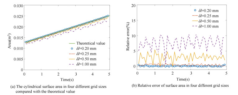
3.1 Verification and Validation of the Level-Set Method and Riemann SolverFig. 1 shows the cylinder model with a length of 200 mm and a radius of 10 mm in initial and burnout state. The surface solved by the level-set method is smooth. Fig. 2(a) presents the cylindrical surface areas at four level-set step sizes and the precision is improved with smaller step. However, the maximum relative error is less than 15% in these sizes (Fig. 2(b)). Other validation concerning complex geometry could be referred to in Wei and Bao's work[27].

|
Fig.1 Testing the level-set method using a cyliner model |
|
Fig.2 Different level-set grid sizes for testing |
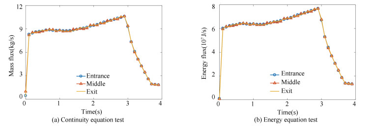
Fig. 3 provides the validation of the Riemann solver of this code and the test model is presented in Fig. 4(a). These test values were taken from the entrance to the exit of the nozzle due to no mass injection. From Fig. 3, the mass flux and energy flux have little difference in the nozzle, which means this solver is valid.
|
Fig.3 Riemann solver for testing |

|
Fig.4 Schematic of the NAWC tactical motor No. 6 |
3.2 Results of NAWC6 Tactical Motor No. 6
First of all, the results calculated by this code have been compared with the results of Rocballist[12] and the experimental trace was reported by Blomshield[28]. All geometric sizes of the NAWC tactical motor No. 6 (Fig. 4) are from Ref. [12], and the basic calculating parameters and the experimental results are respectively from Ref. [12] and Refs. [10, 28]. The geometry of grain in Fig. 4(a) is the same as that in Fig. 4(b), and the only difference is the shape of the nozzle, but both nozzles have the same throat diameter. The model in Fig. 4(a) was used to compare the simulation results with those in the reference and test the burning rate module. The model in Fig. 4(b) was mainly used to test the nozzle erosion module. Table 1 provides the key parameters used in the simulation.
| Table 1 Propellant parameters of Motors No. 6 at 6.9 MPa[28] |
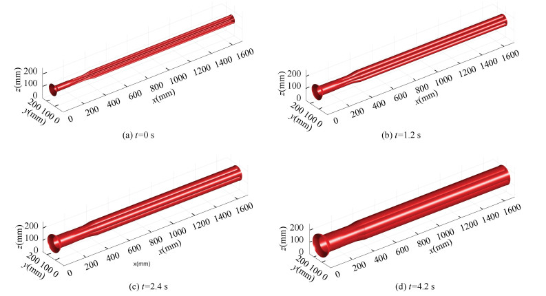
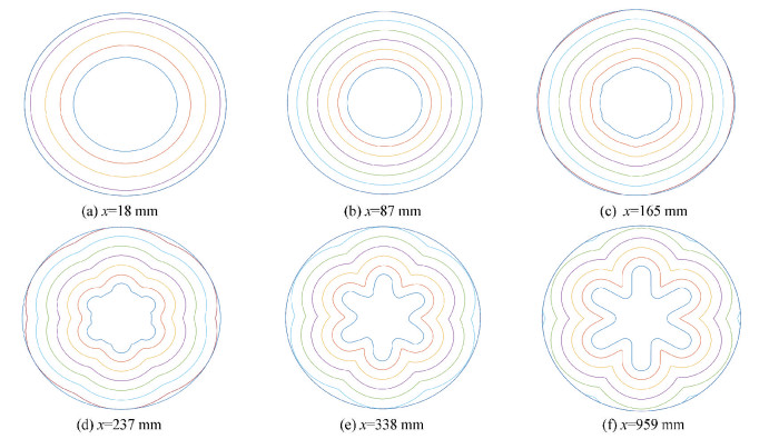
The initial 3D grain surface solved by the level-set method is shown in Fig. 5 and it is also the 3D flowfield initial condition. High-quality initial results could ensure an exact regressing process so that an accurate port area of 3D flowfield can be numerically integrated for the Q1D transient flow field simulation. Fig. 6 shows the six characteristic lateral sections of the grain regressing axially in the normal direction with a constant burning rate in the whole evolution process. The section at 18 mm is larger than that at 237 mm (Fig. 6), so the smaller section needs more time to burn out.
|
Fig.5 Initialization results of the grain at 0 s, 1.2 s, 2.4 s, and 4.2 s |
|
Fig.6 Grain regression with time at six sections (Δt=0.06 s ) |
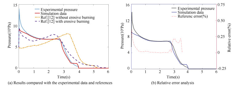
In this study, two main modules were tested as described below. The first one is the burning rate module including the constant burning rate model and APN burning rate model (rb=aPn) which is solely dependent on the mean local pressure. The other module is nozzle erosion. The influence of erosive burning contribution for the propellant was neglected in this study because the burning rate was uniform from head-end to aft-end of the propellant. Considering the complexity of erosive burning and inaccessibility for the entire information from literature, no erosive burning model was implemented in this work. Here our simulation data (head-end pressure) calculated by the constant burning rate model were compared with the experimental data and the results calculated by Rocballist 1D in Fig. 7(a), and our results are significantly better. Fig. 7(b) shows the relative error of our simulation data in contrast to experimental data. When the grain was burning in steady-state (t=0.5 s-3 s), the instantaneous relative error ((| Psimulation-Pexperimental |)/ Pexperimental×100%) of predicted pressure was less than 0.03% and the relative error of total pressure ((| ∫Psimulationdt- ∫Pexperimentaldt |)/∫Pexperimentaldt×100%) was 4.23%. An exact pressure prediction is one of the preconditions to obtain an exact thrust and specific impulse.
|
Fig.7 Head-end pressure-time trace |
In Fig. 7, the pressure-time trace at 3.4 s appears to sidestep, and this phenomenon could be explained in Fig. 8. The dotted line in Fig. 8 is the port area of the burning surface at 3.4 s when the three-fourths of grain aft-end is burnout and the other one-fourths need another 0.6 s.

|
Fig.8 Port area curves of propellant at 0, 1, 2, 3, 3.4, 3.8, and 5 s (The dotted line is the curve at 3.4 s) |
3.3 Burning Rate Module
This code could simulate the ballistic internal flow coupled to burning surface regression with a constant burning rate or APN burning rate. When the constant burning rate model is chosen, the burning surface moves in the normal direction with an input constant speed. When the alternative model is chosen, the burning rate is depended on the chamber pressure at any time. Table 2 shows the basic computing parameters setup, in which the two models (Fig. 4) would use.
| Table 2 Computing parameters |
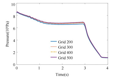
Different grid sizes were used to test the constant burning rate model (Fig. 9) in order to analyze the grid independence of this code. It can be seen that the differences in the pressures for 300 and 500 grid numbers are very small. Accordingly, Table 3 shows the computational time consumed by the four grid numbers. It is obvious that more grid numbers need more compute time. Therefore, less grid number such as 300 can be chosen to simulate the fluid flow under the premise of high accuracy for saving the compute time.
|
Fig.9 Grid independence analysis (r =10.16 mm/s) |
| Table 3 Computing time of four burn surface grids |
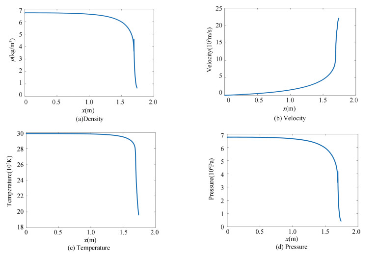
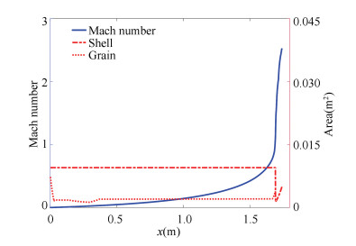
Figs. 10-11 are axial profiles of the flow parameters at t =2 s in the steady-state with burning rate r=10.16 mm/s. As the nozzle is divergent and the gas is compressed at the entrance of the nozzle, an oscillation of the density profile emerges as shown in Fig. 10. The velocity at the nozzle inlet (x=1.693 m) reaches the local sound speed (Fig. 11), and the velocity is increasing but the temperature and pressure are decreasing along with the nozzle axially. Although the pressure wave rather than the shock wave appears in this case, the TVD-MacCormack scheme also could capture the shock wave[20], and the flow distribution can be utilized axially to help the designer to check whether the SRM design is reasonable or not.
|
Fig.10 The axial profiles of density, velocity, temperature, and pressure at t=2 s |
|
Fig.11 The profile of Mach number at t = 2 s |
The constant burning rate model were used to observe the head-end pressure-time trace with different burning rates of the NAWC6 tactical motor No. 6. One is the 8.16 mm/s and the other is 12.16 mm/s. It can be seen from Fig. 12 that different burning rates cause different pressure traces, and the propellant with a low burning rate needs more time to burn out, while the high burning rate needs less time. Different burning rate generates different mass injection rate (Fig. 12(a)), and high mass injection leads to high chamber pressure. When mass injection rate is continuously increasing from t=1 s to 2.5 s for 12.16 mm/s as shown in Fig. 12(b), the pressure is smooth (Fig. 12(c)). This illustrates that the mass injection rate could influence the pressure value rather than its trend, because the port area increases dramatically with the grain rapidly burning in a short period of time so that the density does not change too much. From Fig. 12(c), the specific impulse values under different burning rates are almost the same but the working time is different.

|
Fig.12 Working parameter profiles of the motor at different burning rates |
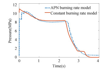
The APN model of this code is shown as follows. The APN model was used to approximate the burning rate and values of a and n, as presented in Table 2. Fig. 13 shows the results calculated by a constant burning rate (r=12.16 mm/s) and APN models. The trends of the pressure-time trace computed by two different models are consistent. From Fig. 13, it can be seen that the pressure profiles are similar, it means that the burning rate calculated by APN model is close to the constant burning rate. Hence, the pressure profiles have similar behavior. Nevertheless, the computational cost is different (Table 4) and the model with constant burning rate is more superior in CPU time. However, because the speed of the APN model is dependent on the pressure value of every time step, it is supposed to be more accurate. But it depends on the comprehensive consideration of the CPU time and accuracy for a real problem since the time step of the level-set equation could be reduced to the same as flow time step (1×10⁻⁷s for this study) in order to get a smoother and more accurate result. On the other side, the improvement of accuracy by sacrificing the CPU time is not always right, as it has been mentioned that the present method is a numerical approximation with some unavoidable error. Hence, when the burning rate is given beforehand, the constant burning rate model could be used instead of the APN model to save compute time. The constant burning rate model can also be used to correct the APN model, the other burning rate model, or SRM aided design.
|
Fig.13 Pressure-time traces of different burning models (r = 12.16 mm/s) |
| Table 4 The computing time of different burning models |
3.4 Nozzle Erosion Module
Nozzle erosion is also an important factor to impact the pressure trace. The rule of nozzle erosion has been studied in many reports. Thakre and Yang[29] established an analysis model to predict the tungsten nozzle erosion and Nasuti[30-31]studied the graphite nozzle erosion in detail. The other module named nozzle erosion module in this code is simpler than these just mentioned above. The rules of nozzle erosion observed by Evans[32]was used to depict the change of throat diameter according to the whole working time without considering the influence of propellant chemical reaction and the whole nozzle erosion. In Fig. 4(b), the geometry model with the Laval nozzle which is different from that in Fig. 4(a) was used to study the characteristic of this Q1D flow influenced by the nozzle erosion. The sizes and shape of grain and shell (Fig. 4(b)) are the same as those in Fig. 4(a).
|
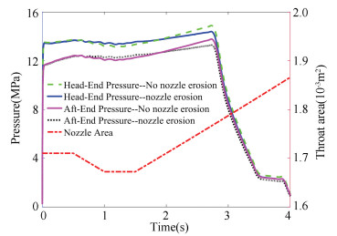
Fig.14 Pressure-time trace and the nozzle throat area (r=10.16 mm/s) |
Fig. 14 shows the pressure traces with and without nozzle erosion which is simulated by the constant burning rate model at 10.16 mm/s.
It can be seen that the head-end pressure with nozzle erosion is higher than without at 1 to 1.5 s and lower after 2 s. Because the nozzle throat area decreased from 0.5 to 1 s and maintained a minimum for 0.5 s, the pressure increased during this period. Then, the nozzle throat area increased persistently after 2 s that induced the pressure lower than that without nozzle erosion. The phenomenon that the nozzle throat first decreased and then increased is because some nozzle material contracts when heated following the ignition process[32]. A better nozzle erosion rule could also be used to replace this rule in this code in the future. The results below are just for the functional tests. Generally, from Fig. 14, the influence of nozzle erosion is very small for the head-end pressure.
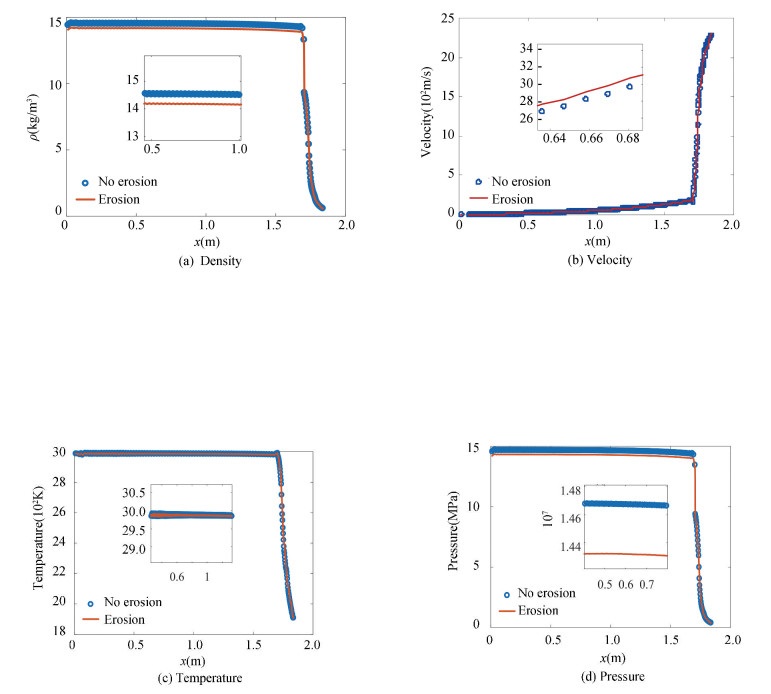
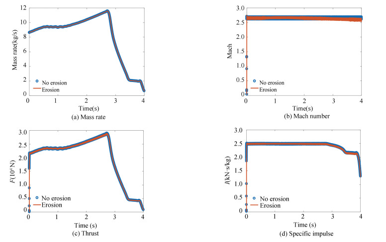
Fig. 15 is the profiles of flow parameters with and without nozzle erosion. It can be seen in Fig. 15 the pressure value with nozzle erosion is just slightly lower than the value without nozzle erosion at 2 s, so these two group values are very close (Fig. 15). In Fig. 15, the density and pressure without nozzle erosion are higher, but the velocity is on the reverse trend because the fuel gas flows faster in the larger nozzle throat and that also accords with the principle of energy conservation. In Fig. 16, the mass injection rate is the same because it is only decided by the burning rate when the constant burning rate model is used. The specific impulse and Mach number at nozzle exit have slight differences after 1.5 s, so does the thrust trace. Although the nozzle erosion could help the pressure trace become smooth (Fig. 14), the SRM working efficiency without nozzle erosion is slightly higher according to the results.
|
Fig.15 Profiles of density, velocity, temperature, and pressure without/with the nozzle erosion at t=2s |
|
Fig.16 Profiles of mass rate, Mach number, thrust, and the specific impulse |
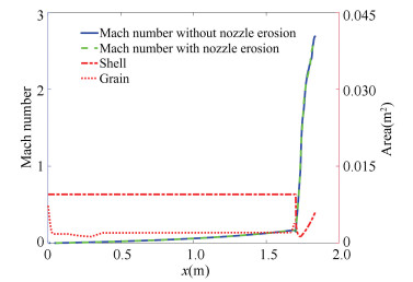
Fig. 17 shows the Mach number distribution axially. Compared with Fig. 11, although their nozzle outlines are different, their nozzle throat sizes are the same. The trends of Mach number in the nozzle are close, but they are very different in the chamber. Thus, the shape of the nozzle could influence the flow profile in the combustion chamber. The Laval nozzle could smooth the velocity profile in the chamber (Fig. 17).
|
Fig.17 Mach number at t =2 s |
4 Conclusions
The simulation of SRM quasi-one-dimension transient compressible flow coupled to the three-dimension grain regression in real-time which is solved by the level-set method is presented in this paper. This code could simulate and output the parameter profiles and tracks of fluid flow from the head-end of the chamber to the exit of the nozzle. Two main modules have been tested in detail. A better result obtained within a short time is one of the advantages of this code and the other is modular implantation. In this paper, two modules were implanted and tested: one is the burning rate module which includes two models now and the other is the nozzle erosion module. In the future, more modules would be developed and implanted into this code. This study shows the burning rates module can simulate the SRM in different states and nozzle erosion module could reappear the head-end pressure spike and velocity profile change. References
| [1] |
Sachdev J S, Groth C P T, Gottlieb J J. A parallel solution-adaptive scheme for multi-phase core flows in solid propellant rocket motors. International Journal of Computational Fluid Dynamics, 2005, 19(2): 159-177. DOI:10.1080/10618560410001729135 (  0) 0) |
| [2] |
Sachdev J S, Groth C P T, Gottlieb J J. Numerical solution scheme for inert, disperse, and dilute gas-particle flows. International Journal of Multiphase Flow, 2007, 33(3): 282-299. DOI:10.1016/j.ijmultiphaseflow.2006.09.001 (  0) 0) |
| [3] |
Sachdev J S, Ahuja V, Hosangadi A, et al. Analysis of flame deflector spray nozzles in rocket engine test stands. Proceedings of the 46th AIAA/ASME/SAE/ASEE Joint Propulsion Conference & Exhibit. Restion, VA: AIAA, 2010. (  0) 0) |
| [4] |
Havlucu M Ö, Kırkköprü K. Numerical simulation of flow in a solid rocket motor: combustion coupled with regressive boundary. Journal of Multidisciplinary Engineering Science and Technology, 2016, 3(1): 3790-3798. (  0) 0) |
| [5] |
Han S, Kim C. Integrated fluid-structure simulation for full burning of a solid-propellant rocket interior. Journal of Propulsion and Power, 2014, 30(4): 883-900. DOI:10.2514/1.B35107 (  0) 0) |
| [6] |
Gueyffier D, Roux F X, Fabignon Y, et al. Accurate computation of grain burning coupled with flow simulation in rocket chamber. Journal of Propulsion and Power, 2015, 31(6): 1761-1776. DOI:10.2514/1.B35736 (  0) 0) |
| [7] |
Andrieu B, Gueyffier D. High-fidelity, dynamic CAD model for propagating surfaces and moving meshes. Procedia Engineering, 2017, 203: 115-127. DOI:10.1016/j.proeng.2017.09.793 (  0) 0) |
| [8] |
Li Q, He G Q, Liu P J, et al. Coupled simulation of fluid flow and propellant burning surface regression in a solid rocket motor. Computers & Fluids, 2014, 93: 146-152. DOI:10.1016/j.compfluid.2014.01.028 (  0) 0) |
| [9] |
Hwang Y-H, Chiang C-H. Simple surface-tracking methods for grain burnback analysis. Journal of Propulsion and Power, 2015, 31(5): 1436-1444. DOI:10.2514/1.B35682 (  0) 0) |
| [10] |
Blomshield F S, Crump J E, Mathes H B, et al. Stability testing of full-scale tactical motors. Journal of Propulsion and Power, 1997, 13(3): 349-355. DOI:10.2514/2.5191 (  0) 0) |
| [11] |
Willcox M A, Brewster M Q, Tang K C, et al. Solid propellant grain design and burnback simulation using a minimum distance function. Journal of Propulsion and Power, 2007, 23(2): 465-75. DOI:10.2514/1.22937 (  0) 0) |
| [12] |
Willcox M A, Brewster M Q, Tang K C, et al. Solid rocket motor internal ballistics simulation using three-dimensional grain burnback. Journal of Propulsion and Power, 2007, 23(3): 575-584. DOI:10.2514/1.22971 (  0) 0) |
| [13] |
Favini B, Cavallini E, Di Giacinto M, et al. An ignition-to-burn out analysis of SRM internal ballistic and performances.Proceedings of the 44th AIAA/ASME/SAE/ASEE Joint Propulsion Conference & Exhibit. Reston, VA: AIAA, 2008, 1-19. DOI:10.2514/6.2008-5141 (  0) 0) |
| [14] |
Cavallini E, Favini B, Di Giacinto M, et al. SRM internal ballistic numerical simulation by SPINBALL model. Proceedings of the 45th AIAA/ASME/SAE/ ASEE Joint Propulsion Conference & Exhibit. Reston, VA: AIAA, 2009, 1-22. DOI:10.2514/6.2009-5512 (  0) 0) |
| [15] |
Ferretti V, Favini B, Cavallini E, et al. Numerical simulations of acoustic resonance of Solid Rocket Motor. Proceedings of the 46th AIAA/ASME/SAE/ASEE Joint Propulsion Conference & Exhibit. Reston, VA: AIAA, 2010, 1-18. DOI:10.2514/6.2010-6996 (  0) 0) |
| [16] |
Cavallini E, Favini B, Di Giacinto M, et al. Internal ballistics simulation of a NAWC tactical SRM. Journal of Applied Mechanics, 2011, 78(5): 051018. DOI:10.1115/1.4004295 (  0) 0) |
| [17] |
Cavallini E, Bianchi D, Favini B, et al. Propellant effects on SRM upper stage internal ballistics and performance with nozzle erosion characterization. Proceedings of the 48th AIAA/ASME/SAE/ ASEE Joint Propulsion Conference & Exhibit. Reston, VA: AIAA,, 2012, 1-16. DOI:10.2514/6.2012-3887 (  0) 0) |
| [18] |
Terzic J, Zecevic B, Baskarad M, et al. Prediction of internal ballistic parameters of solid propellant rocket motors. Problems of Mechatronics, 2011, 4(6): 7-26. (  0) 0) |
| [19] |
Wendt J F. Computational Fluid Dynamics: An Introduction. Berlin: Springer, 1992. DOI:10.1007/978-3-540-85056-4 (  0) 0) |
| [20] |
Davis S F. A simplified TVD finite difference scheme via artificial viscosity. SIAM Journal on Scientific and Statistical Computing, 1987, 8(1): 1-18. DOI:10.1137/0908002 (  0) 0) |
| [21] |
Liang D F, Falconer R A, Lin B L. Comparison between TVD-MacCormack and ADI-type solvers of the shallow water equations. Advances in Water Resources, 2006, 29(12): 1833-1845. DOI:10.1016/j.advwatres.2006.01.005 (  0) 0) |
| [22] |
Xu S, Aslam T, Stewart D S. High resolution numerical simulation of ideal and non-ideal compressible reacting flows with embedded internal boundaries. Combustion Theory and Modelling, 1997, 1(1): 113-142. DOI:10.1080/713665233 (  0) 0) |
| [23] |
Osher S, Fedkiw R, Piechor K. Level set methods and dynamic implicit surfaces. Applied Mechanics Review, 2004, 57(3): B15. DOI:10.1115/1.1760520 (  0) 0) |
| [24] |
Sussman M, Fatemi E. An efficient, interface-preserving level set redistancing algorithm and its application to interfacial incompressible fluid flow. SIAM Journal on Scientific Computing, 1999, 20(4): 1165-1191. DOI:10.1137/S1064827596298245 (  0) 0) |
| [25] |
Solomenko Z, Spelt P D M, Naraigh L O, et al. Mass conservation and reduction of parasitic interfacial waves in level-set methods for the numerical simulation of two-phase flows: a comparative study. International Journal of Multiphase Flow, 2017, 95: 235-256. DOI:10.1016/j.ijmultiphaseflow.2017.06.004 (  0) 0) |
| [26] |
Shu C-W, Osher S. Efficient implementation of essentially non-oscillatory shock-capturing schemes. Journal of Computational Physics, 1988, 77(2): 439-471. DOI:10.1016/0021-9991(88)90177-5 (  0) 0) |
| [27] |
Wei R, Bao F T, Liu Y, et al. Combined acceleration methods for solid rocket motor grain burnback simulation based on the level set method. International Journal of Aerospace Engineering, 2018, 2018: 1-12. DOI:10.1155/2018/4827810 (  0) 0) |
| [28] |
Blomshield F S., Pulsed motor firings, Yang V, Brill T B, Ren W Z. Solid Propellant Chemistry, Combustion, and Motor Interior Ballistics. Reston, VA: AIAA, 2000, 921-958. DOI:10.2514/5.9781600866562.0921.0958 (  0) 0) |
| [29] |
Thakre P, Yang V. Chemical erosion of refractory-metal nozzle inserts in solid-propellant rocket motors. Journal of Propulsion and Power, 2009, 25(1): 40-50. DOI:10.2514/1.37922 (  0) 0) |
| [30] |
Nasuti F, Bianchi D. Carbon-carbon nozzle erosion and shape-change effects in full-scale solid-rocket motors. Journal of Propulsion and Power, 2012, 28(4): 820-830. DOI:10.2514/1.B34267 (  0) 0) |
| [31] |
Bianchi D, Nasuti F. Numerical analysis of nozzle material thermochemical erosion in hybrid rocket engines. Journal of Propulsion and Power, 2013, 29(3): 547-558. DOI:10.2514/1.B34813 (  0) 0) |
| [32] |
Evans B, Kuo K, Ferrara P, et al. Nozzle throat erosion characterization study using a solid-propellant rocket motor simulator. Proceedings of the 43rd AIAA/ASME/SAE/ASEE Joint Propulsion Conference & Exhibit. Reston, VA: AIAA, 2007. DOI:10.2514/6.2007-5776 (  0) 0) |
 2021, Vol. 28


