With the master-slave control, the anthropomorphic manipulator can duplicate the movements of human operator's arm. This method stands out by intuitive simplicity, with a feature to control a large number of degrees of mobility simultaneously. In this case, interaction occurs along the chain "operator-master device-slave device". The master device is intended to capture the movements of the operator and can be based on various technologies.
One of the varieties is the mechanical master devices installed on the operator. These devices are lever mechanisms, the kinematic scheme of which is similar to the operator arm and the links are parallel to the operator's arm[1-2]. Those devices are the so-called exoskeletons. The master devices in the form of an exoskeleton are characterized by relatively low cost (in comparison with the optical motion capture devices) and the ability to work in real time (because of the low computational complexity of data processing).
In this work, relatively simple exoskeletons are considered, which consist of three links, have 7 degrees of mobility and rigid coupling with the operator's arm in the shoulder and wrist joints, as well as flexible coupling in the elbow joint similar to the one described in Ref.[2]. As the exoskeleton kinematic scheme is similar to the operator arm, there is a significant correlation between the rotation angles in the operator's joints and the exoskeleton kinematic pairs. This fact forms the basis of the method used to capture motion in the considered device. Rotation angles measured by the exoskeleton are used to control the anthropomorphic manipulator. However, the exoskeleton joints axes do not coincide with the operator's joints, and the exoskeleton links lengths differ from the operator's arm links lengths. Thus, the arm rotation angles may not be equal to the corresponding exoskeleton rotation angles. The resulting asynchronous behavior between the movement of the anthropomorphic manipulator and the operator's arm increases the complexity of performing fine operations.
The error of the position copying can be decreased by calculating the coordinates of the operator's arm joints using the direct kinematics problem and then the operator's arm rotation angles by solving the inverse kinematics problem. Such approach will capture movements of the operator directly rather than these of a worn exoskeleton. The aim of this article is to develop a method that allows to solve the first of the mentioned problems: calculating the Cartesian coordinates of the operator's arm joints.
The article is structured as follows. Various motion capture technologies and used methods are discussed in Section 1. The developed method is described in Section 2. The results of experiments are shown in Section 3 and discussed in Section 4. Limitations on the applicability of the method are given in Section 5. Section 6 gives the conclusion on the work.
1 Literature ReviewMotion capture techniques described in the scientific literature can be classified into two main types. The first type includes technologies based on the calculation of the Cartesian coordinates of the operator's arm nodal points, e.g., using magnetic[3] or optical[4-5] markers and corresponding sensors or sensors based on inertia[6]. The resulting Cartesian coordinates of the nodal points can be transformed into the rotation angles of the anthropomorphic manipulator[7-10], the Cartesian coordinates of the non-anthropomorphic manipulator[11], or other values, depending on the task. The second type includes devices that measure the rotation angles of the operator's arm directly. Usually these devices are built as exoskeletons with a complex structure, in which the axes of kinematic pairs coincide with the axes of the operator's joints rotation[12-13].
In this work, the focus is on devices similar to the exoskeleton ZUKT-3 produced by JSC SPA "Android Technics"[2]. The exoskeleton under consideration is exceptional from the point of view that it can be assigned to both types mentioned above. The rotation angles of the operator's arm were determined to formulate the control rules of the manipulator, which was assumed to be the one belonging to the second type. The measured rotation angles of the exoskeleton were used as the target ones for the manipulator. However, unlike exoskeletons of a more complex design, in ZUKT3 the rotational axes of kinematic pairs do not coincide with the axes of the joints, which leads to a significant calculation deviation.
In this paper, it is proposed to use ZUKT-3 as a device of the first type, i.e., to calculate the Cartesian coordinates of nodal points with further transformation of Cartesian coordinates into the values necessary to control the manipulator with one of the already existing methods. Since the design of the exoskeleton under consideration is not widespread and is not covered in technical literature, the solution of this problem is proposed for the first time. This paper deals with a new task, rather than with the improvement of existing solutions, and therefore the purpose of the current review is to consider technical literature sources on the possibility of borrowing solutions to particular problems.
The considered device and devices of the first type are similar in the fact that there is a need to solve the inverse kinematics when they are used. General solutions of the inverse kinematics problem for redundant kinematic chains (and for the operator's arm) are given in Refs.[14-16]. The solution of the inverse kinematics of anthropomorphic manipulators was developed in Refs.[7-8].
The design of the exoskeleton allows to consider it as a passive anthropomorphic manipulator. Solution of the direct problem of kinematics, i.e., the determination of the Cartesian coordinates of the couplings of the exoskeleton, has been presented in Refs. [17-18].
2 Materials and Methods 2.1 Mathematical Formulation of the ProblemAn analytical solution of the inverse kinematics has been developed to determine the position of the operator's arm elbow joint without rigid coupling. An analytical solution of the direct kinematics was used to calculate the coordinates of all the remaining joints of the operator's arm and the joints of the exoskeleton.
Fig. 1 demonstrates the kinematic diagram of the interconnected exoskeleton and the operator's arm. The kinematic scheme of the exoskeleton is similar to that of the human arm. This constructive solution is introduced to simplify an interpretation of the angles of rotational kinematic pairs. In the diagram, the letters A, B, C, D and AO, BO, CO, DO designate the shoulder, elbow, radiocarpal, and wrist joints of the exoskeleton and the shoulder, elbow, wrist joints, and the center of the operator's arm, respectively. The points D and DO have a rigid coupling between them and serve as the center of the exoskeleton end effector and the operator's palm, respectively. The shoulder, elbow, and carpal links are designated for the exoskeleton as links AB, BC, CD respectively and for the operator's arm as AOBO, BOCO, CODO, respectively. Rigid connections by the distance between the shoulder and wrist joints of both kinematic chains are designated as AAO and CCO. A, B, C are joints of the exoskeleton analogous to the shoulder, elbow, and wrist joints of the operator's arm AO, BO, CO.

|
Fig.1 Relation of the exoskeleton rotational pairs and the operator's arm joints |
EEO is a virtual link which represents the flexible coupling between the exoskeleton and operator's arm. Since the anthropomorphic manipulator is redundant, it is necessary to determine the elbow joint position to prevent possible obstacle collisions. EEO link is difficult to model with sufficient accuracy, therefore B was used as a reference point to calculate the coordinates of BO.
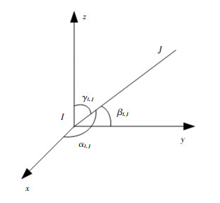
The angle between the arbitrary link IJ and the abscissa axis is denoted as αIJ, the angle between the arbitrary link IJ and the ordinate axis as βIJ, the angle between the arbitrary link IJ and the applicate axis as γIJ as shown in Fig. 2. These angles are the orientation angles of the arbitrary link IJ.
|
Fig.2 Orientation angles of an arbitrary link IJ |
The mathematical formulation of the problem of determining the relative position of the operator's arm and the couplings of the exoskeleton for the anthropomorphic manipulator control systems is shown below.
Input data:
1) The coordinates of the shoulder point of the operator AO(xAO, yAO, zAO);
2) Angles of orientation of rigid couplings αAAO, βAAO, γAAO; αCCO, βCCO, γCCO; αDDO, βDDO, γDDO between the joints of the exoskeleton and the joints of the operator arm; angles of orientation αAB, αBC, αCD; βAB, βBC, βCD; γAB, γBC, γCD of the links AB, BC, CD;
3) The lengths of the links AB, BC, CD of the exoskeleton and the parts of the operator's arm AOBO, BOCO, CODO.
It is required to find the coordinates BO(xBO, yBO, zBO) of the operator's arm elbow joint in the absence of a rigid coupling with the elbow joint B(xB, yB, zB) of the exoskeleton.
2.2 The Method for Determining the Location of the Operator's Arm JointsThe algorithm for determining the relative position of the operator's arm and the joints of the exoskeleton according to the proposed method consists of three steps.
In Step 1, it is necessary to determine positions of the shoulder, elbow, and wrist joints of the exoskeleton A(xA, yA, zA), B(xB, yB, zB), C(xC, yC, zC) respectively, and the position of the palm center D(xD, yD, zD).
The operator's shoulder joint AO is the origin of coordinates, AO=(0, 0, 0). Coordinates of the shoulder joint A(xA, yA, zA) of the exoskeleton are calculated by formulas (1) and (2):
| $ \begin{aligned} \overrightarrow{\boldsymbol{A_{O}} \boldsymbol{A}}=&\left[l_{A_{O}A} \cdot \cos \left(\alpha_{A_{O}A}\right), l_{A_{O}A} \cdot \cos \left(\beta_{A_{O}A}\right), l_{A_{O}A} \cdot\right.\\ &\left.\cos \left(\gamma_{A_{O}A}\right)\right]=\left[A_{O} A_{x}, A_{O} A_{y}, A_{O} A_{z}\right] \end{aligned} $ | (1) |
| $ \boldsymbol{T_{A}}=\left[\begin{array}{cccc} 1 & 0 & 0 & A_{O} A_{x} \\ 0 & 1 & 0 & A_{O} A_{y} \\ 0 & 0 & 1 & A_{O} A_{z} \\ 0 & 0 & 0 & 1 \end{array}\right] \Rightarrow \boldsymbol{A}^{\prime}=\boldsymbol{T_{A}} \cdot \boldsymbol{A}^{\prime}{_\boldsymbol{O}} $ | (2) |
where lAOA is a fixed distance between points A and AO; αAOA, βAOA, γAOA are the guiding angles of
To calculate the coordinates of points B(xB, yB, zB), C(xC, yC, zC), D(xD, yD, zD), the procedure for measuring the generalized coordinates of the links AB, BC, CD by built-in sensors is performed. Then the obtained coordinates are transformed into orientation angles for the corresponding links. The coordinates of points B(xB, yB, zB), C(xC, yC, zC), D(xD, yD, zD) are calculated in the same way as formulas (1) and (2).
The coordinates of point B:
| $ \begin{aligned} \overrightarrow{\boldsymbol{A B}}=&\left[l_{A B} \cdot \cos \left(\alpha_{A B}\right), l_{A B} \cdot \cos \left(\beta_{A B}\right), l_{A B} \cdot\right.\\ &\left.\cos \left(\gamma_{A B}\right)\right]=\left[A B_{x}, A B_{y}, A B_{z}\right] \end{aligned} $ | (3) |
| $ \boldsymbol{T}_{\boldsymbol{B}}=\left[\begin{array}{cccc} 1 & 0 & 0 & A B_{x} \\ 0 & 1 & 0 & A B_{y} \\ 0 & 0 & 1 & A B_{z} \\ 0 & 0 & 0 & 1 \end{array}\right] \Rightarrow \boldsymbol{B}^{\prime}=\boldsymbol{T}_{\boldsymbol{B}} \cdot \boldsymbol{A}^{\prime} $ | (4) |
The coordinates of point C:
| $ \begin{aligned} \overrightarrow{\boldsymbol{B C}}=&\left[l_{B C} \cdot \cos \left(\alpha_{B C}\right), l_{B C} \cdot \cos \left(\beta_{B C}\right), l_{B C}\cdot \right.\\ &\left.\cos \left(\gamma_{B C}\right)\right]=\left[B C_{x}, B C_{y}, B C_{z}\right] \end{aligned} $ | (5) |
| $ \overrightarrow{\boldsymbol{T_{C}}}=\left[\begin{array}{cccc} 1 & 0 & 0 & B C_{x} \\ 0 & 1 & 0 & B C_{y} \\ 0 & 0 & 1 & B C_{z} \\ 0 & 0 & 0 & 1 \end{array}\right] \Rightarrow \boldsymbol{C}^{\prime}=\boldsymbol{T_{C}} \cdot \boldsymbol{B}^{\prime} $ | (6) |
The coordinates of point D:
| $ \begin{aligned} \overrightarrow{\boldsymbol{C D}}=&\left[l_{C D} \cdot \cos \left(\alpha_{C D}\right), l_{C D} \cdot \cos \left(\beta_{C D}\right), l_{C D}\cdot \right.\\ &\left.\cos \left(\gamma_{C D}\right)\right]=\left[C D_{x}, C D_{y}, C D_{z}\right] \end{aligned} $ | (7) |
| $ \boldsymbol{T_{D}}=\left[\begin{array}{cccc} 1 & 0 & 0 & C D_{x} \\ 0 & 1 & 0 & C D_{y} \\ 0 & 0 & 1 & C D_{z} \\ 0 & 0 & 0 & 1 \end{array}\right] \Rightarrow \boldsymbol{D}^{\prime}=\boldsymbol{T_{D}} \cdot \boldsymbol{C}^{\prime} $ | (8) |
In Step 2, the position of the operator's joints in the coordinate space (which are in rigid coupling with the exoskeleton) should be determined.
Displacement
| $ \begin{aligned} \overrightarrow{\boldsymbol{C C_{O}}}=&\left[l_{C C_{O}} \cdot \cos \left(\alpha_{C C_{O}}\right), l_{C C_{O}} \cdot \cos \left(\beta_{C C_{O}}\right), l_{C C_{O}}\cdot\right.\\ &\left.\cos \left(\gamma_{C C_{O}}\right)\right]=k\left[C C_{O{x}}, C C_{O{y}}, C C_{O z}\right] \end{aligned} $ | (9) |
| $ \boldsymbol{T}_{\boldsymbol{C_{O}}}=\left[\begin{array}{cccc} 1 & 0 & 0 & C C_{O x} \\ 0 & 1 & 0 & C C_{O y} \\ 0 & 0 & 1 & C C_{O z} \\ 0 & 0 & 0 & 1 \end{array}\right] \Rightarrow \boldsymbol{C}^{\prime}{}_{\boldsymbol{{O}}}=\boldsymbol{T}_{\boldsymbol{C_{O}}} \cdot \boldsymbol{C}^{\prime} $ | (10) |
where lCCO is a fixed distance between points C and CO; αCCO, βCCO, γCCO are the guiding angles of CCO .
The coordinates of the operator's palm center DO(xDO, yDO, zDO) can be determined by shifting the point D of the exoskeleton along the rigid coupling vector using formulas (11) and (12):
| $ \begin{aligned} \overrightarrow{\boldsymbol{D D_{O}}}=&\left[l_{D D_{O}} \cdot \cos \left(\alpha_{D D_{O}}\right), l_{D D_{O}} \cdot \cos \left(\beta_{D D_{O}}\right), l_{D D_{O}} \cdot\right.\\ &\left.\cos \left(\gamma_{D D_{O}}\right)\right]=\left[D D_{O x}, D D_{O{y}}, D D_{O z}\right] \end{aligned} $ | (11) |
| $ \boldsymbol{T}_{\boldsymbol{D_{O}}}=\left[\begin{array}{cccc} 1 & 0 & 0 & D D_{O{x}} \\ 0 & 1 & 0 & D D_{O y} \\ 0 & 0 & 1 & D D_{O z} \\ 0 & 0 & 0 & 1 \end{array}\right] \Rightarrow \boldsymbol{D}^{\prime}{}_{\boldsymbol{O}}=\boldsymbol{T}_{ \boldsymbol{DO}} \cdot \boldsymbol{D}^{\prime} $ | (12) |
where lDDO is a fixed distance between points D and DO; αDDO, βDDO, γDDO are the guiding angles of DDO .
Step 3 involves calculation of coordinates BO(xBO, yBO, zBO) of the operator's arm elbow joint on the basis of the analytical solution of the inverse kinematics problem.
The lengths of the vectors
| $ l_{A_{O} C_{O}}=\sqrt{\left(x_{C_{O}}-x_{A_{O}}\right)^{2}+\left(y_{C_{O}}-y_{A_{O}}\right)^{2}+\left(z_{C_{O}}-z_{A_{O}}\right)^{2}} $ | (13) |
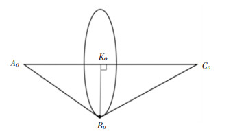
Because the lengths of the parts of the operator's arm can be considered constant in the framework of the problem, the set of possible elbow coordinates forms a circle, and is drawn by point BO as it rotates about the line AOCO. Fig. 3 shows a circle OO(KO, KOBO) circumscribed by point BO as it rotates around a straight line AOCO, where point K0 of intersection of the altitude is drawn from point BO to side AOCO, dividing it in half, assuming the equality of lengths of the vectors
| $ K_{O}\left(x_{K_{O}}, y_{K_{O}}, z_{K_{O}}\right)=\left(\frac{x_{C_{O}}+x_{A_{O}}}{2}, \frac{y_{C_{O}}+y_{A_{O}}}{2}, \frac{z_{C_{O}}+z_{A_{O}}}{2}\right) $ | (14) |
|
Fig.3 Circle circumscribed by a point as it rotates around a straight line |
The circle OO(KO, KOBO) in Fig. 3 can be represented as an intersection of a plane, which is perpendicular to the vector AOCO and passes through point KO, and a sphere with a center at point KO and radius KOBO:
| $ \left\{\begin{array}{l} \left(x-x_{K_{O}}\right)^{2}+\left(y-y_{K_{O}}\right)^{2}+\left(z-z_{K_{O}}\right)^{2}=l_{K_{O} B_{O}}^{2} \\ A_{n} x+B_{n} y+C_{n} z+D_{n}=0 \end{array}\right. $ | (15) |
where
| $ A_{n}=A_{O} C_{O x} ; B_{n}=A_{O} C_{O y} ; C_{n}=A_{O} C_{O z} $ |
| $ D_{n}=-A_{n} \cdot x_{K_{O}}-B_{n} \cdot y_{K_{O}}-C_{n} \cdot z_{K_{O}} $ |
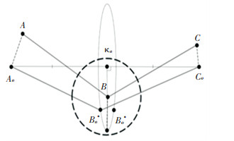
It is assumed that the distance between joints B and B0 is constant. Then the coordinates of the point BO* on the circle OO(KO, KOBO) can be determined by finding the points of intersection with the sphere (B, BBO). The sphere OBBO(B, BBO) has a center at the point B, which is shown in Fig. 4. The equation of this sphere is as follows:
| $ \left(x-x_{B}\right)^{2}+\left(y-y_{B}\right)^{2}+\left(z-z_{B}\right)^{2}=B B_{O}^{2} $ | (16) |

|
Fig.4 Sphere OBBO(B, BBO) |
The spatial coordinates (xBO, yBO, zBO) of point BO* are the points of intersection of a circle OO(KO, KOBO) with a sphere (B, BBO)(Fig. 5).
|
Fig.5 Location of point BO* in space as a point of intersection of a circle OO(KO, KOBO) with a sphere (B, BBO) |
Thus, the possible coordinates (xBO, yBO, zBO) of a point BO are determined by solving a system of nonlinear formulas
| $ \left\{\begin{array}{l} \left(x_{B_{O}}-x_{K_{O}}\right)^{2}+\left(y_{B_{O}}-y_{K_{O}}\right)^{2}+\left(z_{B_{O}}-z_{K_{O}}\right)^{2}=l_{K_{O} B_{O}}^{2} \\ \left(x_{B_{O}}-x_{B}\right)^{2}+\left(y_{B_{O}}-y_{B}\right)^{2}+\left(z_{B_{O}}-z_{B}\right)^{2}=l_{B B_{O}}^{2} \\ A_{n} x+B_{n} y+C_{n} z+D_{n}=0 \end{array}\right. $ | (17) |
The desired position of point BO can be chosen from two resulting points. The selection is determined by the built-in condition, for instance, by minimizing the rotation of the links of the executive device, minimizing power consumption, selecting the minimum span and the shortest distance BBO, etc. The method given in Ref. [18] can be used to determine the rotation angles of the anthropomorphic manipulator.
3 ResultsThe coordinates BO(xBO, yBO, zBO) of the elbow joint of the operator's arm will be calculated in the absence of a rigid coupling with the elbow joint B(xB, yB, zB) of the exoskeleton by the initial data presented in Table 1 to illustrate the proposed method on a real example.
| Table 1 Input data for testing |
The coordinates of the couplings A(xA, yA, zA), B(xB, yB, zB), C(xC, yC, zC), D(xD, yD, zD) of the exoskeleton are calculated by formulas (1)-(8). The coordinates of the wrist joint CO(xCO, yCO, zCO) and center DO(xDO, yDO, zDO) of the operator's arm are obtained using formulas (9)-(12).
In the third stage, the length of the vector
| Table 2 Calculation results |
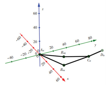
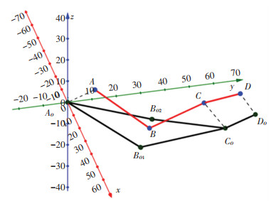
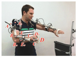
The resulting positions of the arm joints and the center of the operator's hand are shown in Fig. 6, where the points AO, BO1, BO2, CO, DOrepresent the coordinates of the operator's arm joints; AO represents shoulder joint; BO1 and BO2 represent variants of elbow joint position; CO represents wrist joint center; and DO represents hand center. The points BO1 and BO2 are two calculated variants of the location of the elbow joint. The visual representation of the interconnection of exoskeleton and operator's arm joints are shown in Fig. 7, which demonstrates the positions of the rigid couplings between the exoskeleton A, B, C, D and the operator's arm AO, BO, CO, BO, where A represents exoskeleton shoulder joint center; B represents exoskeleton elbow joint center; C represents exoskeleton wrist joint center; D represents exoskeleton hand center; AO represents operator's shoulder joint center; BO1 and BO2 represent variants of operator's elbow joint center; CO represents operator's wrist joint center; DO represents operator's hand center.
|
Fig.6 The position of the operator's arm joints centers |
|
Fig.7 The position of the exoskeleton nodes and the operator's arm joints |
Physical experiments were conducted to test the operability and evaluate the effectiveness of the proposed method. The method was programmatically implemented and integrated in the software complex of the ZUKT-3 exoskeleton master-slave control system (Fig. 8).
|
Fig.8 Experimental exoskeleton |
The length of the flexible coupling EEO was set at four different values. For each value of the length, operator's arm was put at 10 different positions. The angles of the arm were measured with a digital protractor and then compared with the angles, which were obtained with the exoskeleton and processed in accordance with the proposed method. On each iteration the maximal difference between measured and computed value was used as the error. The method was also compared with the existing one[19], where the values measured by the exoskeleton were directly used as the rotation angles of the operator's arm.
The results of the experiment are shown in Table 3. By changing the length of the flexible coupling EEO, the average error of the master-slave teleoperation was reduced from 20.7° for the existing method to 2.9° for the proposed method and the flexible coupling length was 9.0 cm (which is the minimal possible value). These results indicate the effectiveness of the developed method. Another positive result is a decrease in root-mean-square (RMS) deviation of the error. According to the subjective sensations of the operator, the proposed method made the control process more convenient.
| Table 3 Results of the experiment |
As the efficiency of the method decreases with the increase of the flexible coupling EEO length, and for the length of 12.0 cm the average error is worse than that of the analogue method, the length of EEO should be kept as low as possible.
4 DiscussionThe developed method makes it possible to calculate the Cartesian coordinates of the shoulder, elbow, and wrist joints of the operator's arm, as well as the center of his palm. The length of the virtual coupling between the elbow joint and the elbow coupling of the exoskeleton is a controlled parameter. The experiment proved the capability of the proposed method to reduce the error of master-slave control from 20.7° to 2.9° by properly choosing this parameter.
The calculation by formulas (1)-(14) in conjunction with the solution of the system of formulas(17) requires the implementation of approximately 4×10² of math operations. This number is significantly smaller than the number of operations that must be performed when capturing motion using optical or magnetic markers and image recognition[3-6]. The calculations are planned to be performed using a personal computer that is part of the master-slave control system. Relatively low computational complexity allows the performance of real-time teleoperation.
The enhancement of the accuracy of the ZUKT-3 exoskeleton will allow finer operations with it. Its relatively low cost will positively affect its application in various areas where it is necessary to replace operator presence due to dangerous environments such as under water, in space, under conditions of high radiation, etc.
5 LimitationsThe proposed method has several limitations. The method is based on the assumption that the exoskeleton is an anthropomorphic manipulator that is rigidly coupled to the operator's arm in the shoulder and wrist joints, and the center of the arm is connected by a flexible coupling in the elbow joint. Thus, the proposed method is suitable only for exoskeleton such as ZUKT-3. The second limitation is due to the fact that when modeling the operator's arm and the exoskeleton, the operator's backlash in rigid couplings, the backlash of the kinematic pairs of the exoskeleton, and the elasticity of the joints of the operator's arm were not taken into account. Problems of this kind have been addressed in Ref. [20], but the applicability of the proposed methods to ZUKT-3 needs further investigation.
6 ConclusionsTo achieve the goal, the operator's arm and the exoskeleton were modeled in the form of an interconnected anthropomorphic manipulators pair. In the model under study, the shoulder and wrist joints, as well as the ends effectors of the manipulators, are rigidly interconnected, while the elbow joints are interconnected by a flexible coupling. Based on the constructed mathematical model, an analytical method was developed for calculating the Cartesian coordinates of the operator's arm joints centers. The novelty of the proposed method is that some attachments of the exoskeleton to the operator body are not modeled as rigid connections, but as flexible connections with a constant distance. The experiment showed that the proposed method reduces the error of the master-slave control in total for all degrees of mobility from 20.7° to 2.9°.
| [1] |
GOST R 60.0.7.1-2016. Robots and Robotic Devices. Techniques for Programming and Operator Interaction (in Russian). http://docs.cntd.ru/document/1200142414, 2020-07-27.
(  0) 0) |
| [2] |
JSC SPA "Android Technics". Module 'The Master Device of the Copying Type'. https://web.archive.org/web/20170716031333/http://npo-at.com/products/%C2%AB%D0%B0%D0%B2%D0%B0%D1%82%D0%B0%D1%80%C2%BB/, 2020-07-27.
(  0) 0) |
| [3] |
Bluethmann W, Ambrose R, Diftler M, et al. Robonaut: a robot designed to work with humans in space. Autonomous Robots, 2003, 14: 179-197. DOI:10.1023/A:1022231703061 (  0) 0) |
| [4] |
Diftler M A, Mehling J S, Abdalla M E, et al. Robonaut 2 - The first humanoid robot in space. Proceedings of the 2011 IEEE International Conference on Robotics and Automation. Piscataway: IEEE, 2011, 2178-2183. DOI:10.1109/ICRA.2011.5979830 (  0) 0) |
| [5] |
Ke W D, Peng Z P, Cai Z S, et al. Study of trajectory tracking control for humanoid robot based on similarity locomotion. Acta Automatica Sinica, 2014, 40(11): 2404-2413. DOI:10.3724/SP.J.1004.2014.02404 (  0) 0) |
| [6] |
Koenemann J, Burget F, Bennewitz M. Real-time imitation of human whole-body motions by humanoids. Proceedings of the 2014 IEEE International Conference on Robotics and Automation (ICRA). Piscataway: IEEE, 2014, 2806-2812. DOI:10.1109/ICRA.2014.6907261 (  0) 0) |
| [7] |
Kim H, Miller L M, Byl N, et al. Redundancy resolution of the human arm and an upper limb exoskeleton. IEEE Transactions on Biomedical Engineering, 2012, 59(6): 1770-1779. DOI:10.1109/TBME.2012.2194489 (  0) 0) |
| [8] |
Kim H, Kim J. Control of the seven-degree-of-freedom upper limb exoskeleton for an improved human-robot interface. Journal of the Korean Physical Society, 2017, 70: 726-734. DOI:10.3938/jkps.70.726 (  0) 0) |
| [9] |
Petrenko V, Tebueva F, Gurchinsky M, et al. The Concept of Human Learning Professional Movements Using Exoskeleton Complex. http://ceur-ws.org/Vol-2494/paper_25.pdf, 2020-07-27.
(  0) 0) |
| [10] |
Petrenko V, Tebueva F, Gurchinsky M, et al. Development of the structure of the upper-limb exoskeleton for operator's motion capture with master-slave control. Atlantis Press Series: Advances in Intelligent Systems Research, 2019, 166: 152-158. DOI:10.2991/itids-19.2019.28 (  0) 0) |
| [11] |
Shi Z, Huang X X, Hu T J. Human motion capture similarity control for space teleoperation. Shen R, Dong G. Proceedings of the 28th Conference of Spacecraft TT&C Technology in China. TT&C 2016. Lecture Notes in Electrical Engineering. Singapore: Springer, 2017. 263-279. DOI: 10.1007/978-981-10-4837-1_21.
(  0) 0) |
| [12] |
Cempini M, De Rossi S M M, Lenzi T, et al. Self-alignment mechanisms for assistive wearable robots: a kinetostatic compatibility method. IEEE Transactions on Robotics, 2013, 29(1): 236-250. DOI:10.1109/TRO.2012.2226381 (  0) 0) |
| [13] |
Rose C G, Kann C K, Deshpande A D, et al. Estimating anatomical wrist joint motion with a robotic exoskeleton. IEEE International Conference on Rehabilitation Robotics, 2017, 2017: 1437-1442. DOI:10.1109/icorr.2017.8009450 (  0) 0) |
| [14] |
Zaplana I, Basanez L. A novel closed-form solution for the inverse kinematics of redundant manipulators through workspace analysis. Mechanism and Machine Theory, 2018, 121: 829-843. DOI:10.1016/j.mechmachtheory.2017.12.005 (  0) 0) |
| [15] |
Oh J, Bae H, Oh J H. Analytic inverse kinematics considering the joint constraints and self-collision for redundant 7DOF manipulator. Proceedings of the 2017 1st IEEE International Conference on Robotic Computing (IRC). Piscataway: IEEE, 2017, 123-128. DOI:10.1109/IRC.2017.46 (  0) 0) |
| [16] |
Yan W B, Sun L. An optimization method for inverse kinematics of a 7-DOF redundant manipulator. Proceedings of the 2015 34th Chinese Control Conference (CCC). Piscatway: IEEE, 2015, 4472-4479. DOI:10.1109/ChiCC.2015.7260331 (  0) 0) |
| [17] |
Tondu B. Kinematic modelling of anthropomorphic robot upper limb with human-like hands. Proceedings of the 2009 International Conference on Advanced Robotics. Piscataway: IEEE, 2008, 1-9. (  0) 0) |
| [18] |
Petrenko V I, Tebueva F B, Gyrchinsky, et al. The method of forming a geometric solution of the inverse kinematics problem for chains with kinematic pairs of rotational type only. IOP Conference Series: Materials Science and Engineering, 2018, 450(4): 042016. DOI:10.1088/1757-899X/450/4/042016 (  0) 0) |
| [19] |
Bogdanov A, Zhydenko I, Kiyatkin D, et al. Kopiruyushchiy Manipulyator[Master-Slave Manipulator] (in Russian). Utility Model RU 135 956 U1. 2013. https://new.fips.ru/registers-doc-view/fips_servlet?DB=RUPM&DocNumber=135956&TypeFile=html, 2020-07-27.
(  0) 0) |
| [20] |
Yang C G, Jiang Y M, He W., et al. Adaptive parameter estimation and control design for robot manipulators with finite-time convergence. IEEE Transactions on Industrial Electronics, 2018, 65(10): 8112-8123. DOI:10.1109/TIE.2018.2803773 (  0) 0) |
 2021, Vol. 28


