A slinger is a rotary atomizing device that exhibits the advantages of a simple structure, light weight, high mass flowrate limit, and good atomization performance[1]. It is mainly used in the combustion chamber of micro and small turbo engines[2-3]. In a manner similar to the rotary disc or rotary cup, the liquid is accelerated by the slinger and is then tangential to the air at a high speed to break into micro drops. The difference is that the liquid is thrown out from the edge of the rotary disc (or rotary cup) while it is thrown out through the orifice in the slinger, hence the shape, size, and length of the orifice affect the slinger's atomization.
In 1980, Morishita[4] gathered liquid drops that are thrown out from the slinger with a glass piece, measured the size of the droplets on the glass, and approximately determined spray Sauter Mean Diameter (SMD) change rules. The results indicate that the spray SMD is proportional to the U-0.7, and U denotes the line speed at the edge of the slinger. In 2002, Dahm et al.[5-7] examined liquid regime in the orifice of the slinger and the parameters that affected it. Specifically, the liquid inside the slinger flows into the orifice along the orifice circumference in the form of liquid film and then accumulates to the orifice side (which is opposite to the slinger's rotation direction under the Coriolis force). When the liquid leaves the orifice, it completely accumulates on the side of the orifice and is termed stream mode. If the liquid is not completely accumulated on one side of the orifice, it is termed film mode. When the orifice exhibits an angle with a small curvature, such as the four corners of a square orifice, liquid preferentially gathers on the four corners and is thrown out. In 2008, Sescu et al.[8-11] conducted a series of tests and numerical simulations on the slinger. Their findings are as follows: 1) After the liquid leaves the slinger, the distance of the liquid breaking into droplets increases with increases in the flowrate and decreases with increases in the rotary speed; 2) The liquid spray SMD increases with increases in the flowrate and decreases with increases in the rotary speed; 3) The spatial distribution range of the liquid spray in the slinger radial direction increases with increases in the flowrate and decreases with increases in the rotary speed; 4) Increases in the diameter of the orifice of the slinger can decrease the distance of the liquid breaking into droplets and reduce the spray SMD. Choi et al.[12-15] investigated liquid regime near the orifice of the slinger and liquid spray characteristics of various orifices via high-speed camera and phase doppler particle analyzer (PDPA). They observed that at low rotary speeds or large flowrates, the liquid near the orifice is broken in an irregular manner and increases droplet size. The selection of an appropriate diameter for the orifice and number of orifices can avoid irregular breaking. The effect of the airflow in the axial direction on the atomization of the slinger was also examined. When the velocity of the axial airflow is low, the rotary speed of the slinger dominates liquid atomization. Axial airflow dominates liquid atomization when the velocity of the axial airflow reaches a certain value.
The liquid spray spatial distribution of the slinger changes when the work conditions of the slinger change. Prior studies typically measured the spray parameters at a fixed point to determine the atomization law of the slinger, and it is not possible to offset the effect of the spray spatial distribution change on spray. They also focused on the spray SMD and did not examine the uniformity of the spray. The present study attempts to avoid the effect of the spray spatial distribution change and determine the manner in which the liquid spray SMD and uniformity change with changes in the orifice's shape/size/length. It also attempts to prove that liquid regime in the orifice affects spray SMD and uniformity, and to determine the change rules of the spray when the liquid surface tension changes.
1 Test DeviceThe test device is shown in Fig. 1. The test slinger is driven by a motor mounted on a bracket. The rotary speed of the motor is in the range of 0-24 kr/min and controlled by a frequency regulator, and the minimum adjustment unit corresponds to 6 r/min. A transparent shaft is installed on the periphery of the test slinger to collect the liquid splashed from the slinger and return it to the liquid storage tank. The liquid in the tank is driven by a pump, passes through the filter, pump, valve, and mass flowrate meter, and is ejected from the inject tube and hits on the wall of the slinger to restart a new liquid cycle. The valve is a fine-tuning valve, which can precisely adjust the liquid flowrate. The minimum measuring unit of the mass flowrate meter corresponds to 0.1 g/s, and the measuring range approximately corresponds to 0-40 g/s. The measurement equipment of the test includes a high-speed camera and a PDPA. The high-speed camera is used to capture the liquid regime near the orifice of the slinger, and maximum shooting frequency corresponds to 2500 fps. The PDPA is used to measure liquid spray parameters such as SMD and droplet distribution. The smallest measurement unit of PDPA is related to its laser wavelength, which is about 0.5 μm. The measure accuracy of PDPA is concerned with the types and the shape of the test particles. When measuring the liquid spray droplets, the relative error of speed measurement is 0.2%, the droplet size is 0.5%, and the number of the droplet is 1%[16].

|
Fig.1 Schematic diagram of the test rig |
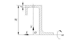
Fig. 2 shows a schematic view of the structure of the test slinger. In the figure, the X-axis of the XOY coordinate system coincides with the axis of the slinger, and the Y-axis coincides with the center line of the orifice. Specifically, R denotes the outer diameter of the slinger, l denotes the length of the slinger, ω denotes the rotary speed of the slinger, and the unit is r/min or kr/min. The test slinger only includes one orifice to prevent mutual interference between multiple orifices. The mass flowrate of the slinger corresponds to the mass flowrate of the liquid passing through the single orifice expressed in m, and the unit of the flowrate is g/s.
|
Fig.2 Schematic diagram of the slinger |
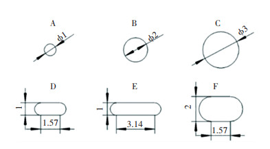
As shown in Fig. 3, the shapes of the orifices are selected from the two most common shapes used in actual slingers: circular and slot. Orifices A-C are round and are used to examine the effect of different diameters on the atomization performance of the slinger. The long side of Orifices D-F are parallel to the axis of the slinger and used to investigate the effect of slot orifice with different parameters on the atomization performance of the slinger. Among them, Orifices D and E were compared to examine the effect of the slot length, and Orifices E and F were used to investigate the effect of slot width. The circumference of Orifice D is the same as that of Orifice B, and the circumference of Orifices E and F is the same as that of Orifice C. They were used to investigate the effects of the orifices with different shapes on the atomization performance of the slinger. The outer diameter of the slinger was constant during the test and corresponds to R=50 mm. The length l of the orifices corresponded to 3 and 6 mm. The orifices with length l=3 mm were used as the baseline group, and the orifices with length l=6 mm were used as the comparison group. The baseline group includes Orifices A-F, and the comparison group includes Orifices B and D.
|
Fig.3 Schematic diagram of the orifices' shapes and sizes(Unit: mm) |
During the test, the mass flowrate was adjusted to a certain value, and the rotary speed was then changed from low to high. The liquid regime near the orifice was simultaneously captured by the high-speed camera, and the parameters of the liquid spray were measured via the PDPA. Subsequently, the liquid mass flowrate was changed and the rotary speed was readjusted to take measurements again. Water was mainly used as the test liquid, and the sulfonic acid was added in the water to change the liquid surface tension to examine the effect of different liquid surface tensions on atomization. The liquid property is shown in Table 1. In Solutions II and III, the volume of water significantly exceeded the volume of the sulfonic acid, thus the effect of the sulfonic acid on the solution viscosity was neglected. It is considered that the viscosities of Solutions I, II, and III are the same, and only the surface tensions are different. Solution I was used as the test liquid except while studying the effect of liquid surface tension on atomization.
| Table 1 Property of the test liquid |
During the test, PDPA was used to measure the liquid spray parameters at a series of points near the slinger to determine the spatial distribution of the spray. The coordinates of the points are shown in Table 2, and the coordinate system is shown in Fig. 2.
| Table 2 Positions of measuring points |
2 Results and Discussion 2.1 Liquid Spray Parameters Calculation
| $ d_{32}=\sum\limits_{i=1}^{N} d_{i}^{3} /\sum\limits_{i=1}^{N} d_{i}^{2} $ | (1) |
| $ \begin{gathered} N_{t}=N /t \end{gathered} $ | (2) |
| $ Q=1-e^{-\left(\frac{d}{d_{0}}\right)^{n}} $ | (3) |
| $ \ln \left(\ln \left(R^{-1}\right)\right)=n \ln d-n \ln d_{0} $ | (4) |
The PDPA can measure the diameter, velocity, and moving direction of all droplets passing through a certain point in space at a given time. By analyzing the diameter of all droplets, liquid spray parameters, such as SMD, concentration, and RR (Rosin-Rammler) distribution index at the measurement point, were obtained. Spray SMD was calculated by Eq.(1), where d32 represents SMD, N denotes the number of measured liquid droplets, and di denotes the diameter for each respective droplet. Additionally, Nt denotes the number of droplets passing through the measuring point per unit time and was calculated by Eq.(2), where t denotes the measuring time. The RR distribution was typically used to describe the diameter distribution of a liquid spray and calculated by Eq.(3), where Q denotes the volume fraction of all droplets smaller than the diameter d in the liquid spray, and d0 denotes the characteristic diameter (indicating that the volume fraction of droplets with smaller diameter than d0 corresponds to 63.2%). Furthermore, n denotes the liquid spray distribution index (increases in n decrease the range of the droplets diameter and increase uniformity of the liquid spray). Two natural logarithmic calculations were performed on both sides of Eq.(3) and Eq.(4) was obtained, which is a linear function with independent variable d and dependent variable ln(ln(R-1)). Based on the droplet data measured by PDPA, the RR distribution index n was calculated via a linear fit.
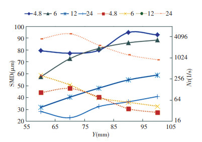
2.2 Spatial Distribution of the Liquid Spray 2.2.1 Spatial distribution of SMD/quantity concentration/volume concentrationThe concentration of the liquid spray in space was measured via two parameters, namely quantity concentration and volume concentration. Quantity concentration denotes the number of the droplets passing through the measuring point per unit time and equals to Nt. Volume concentration denotes the volume sum of the droplets passing through the measuring point per unit time and is represented by Vt. As shown in Fig. 4, the quantity concentration of the liquid spray is inversely proportional to spray SMD. This means that increases in SMD decrease quantity concentration. Decreases in SMD cause the liquid to break into more droplets, which increases the quantity of droplets. The SMD decreases with increases in rotary speed, therefore the quantity concentration increases with increases in rotary speed.
|
Fig.4 Curves of SMD/quantity concentration distribution in the radial direction (Orifice A, m =1 g/s, the solid line indicates SMD, the dotted line indicates quantity concentration, and the number in the legend indicates rotary speed, unit in kr/min) |
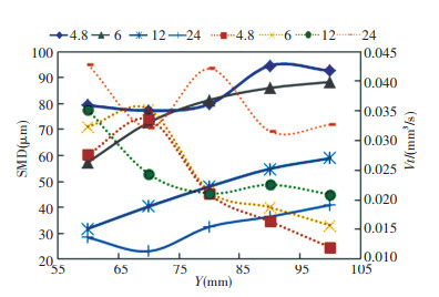
As shown in Fig. 5, the volume concentration of the liquid spray does not exhibit evident regularity with the SMD. The volume concentration of the liquid is equal to the average volume of the droplets in the spray multiplied by the quantity concentration. As shown in Fig. 4, the two parameters are inversely proportional, thus changes in volume concentration are irregular. When the rotary speed ranges between 6 and 12 kr/min, the volume concentration does not increase significantly with increases in the rotary speed.
|
Fig.5 Curves of SMD/volume concentration distribution in the radial direction (Orifice A, m =1 g/s, the solid line indicates SMD, the dotted line indicates quantity concentration, and the number in the legend indicates rotation speed, unit in kr/min) |
The results indicate the other orifices exhibit the same liquid spray SMD/Nt/Vt distribution characteristics at different mass flowrates or rotary speeds. It is known that the volume concentration is determined by the diameter and quantity of the droplets. In the case of poor atomization, it is likely to be high due to the large volume of a single droplet, and it is not possible to evaluate the evaporation and combustion performance of the liquid spray accurately. Typically, decreases in the SMD increase the quantity concentration and increase the combustion performance of the liquid spray. Hence, the quantity concentration is more appropriate for evaluating the concentration distribution of the liquid spray in space.
2.2.2 Spatial distribution of liquid spray SMD in radial direction of a slingerBased on extant studies, for all types of atomizers, after the liquid is ejected from the nozzle, it is broken into small droplets under the action of air shearing force and then aggregated into large droplets due to collision between the droplets. Therefore, increases in the distance between the droplets and atomizer initially decrease the liquid spray SMD and then cause it to increase. The aforementioned phenomenon is also applicable to the slinger.
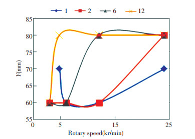
2.2.2.1 Location of the minimum SMDAs shown in Fig. 6, when the rotary speed is less than 12 kr/min, an evident relationship does not exist between the location of the minimum SMD and mass flowrate/rotary speed. However, when the rotary speed reaches 12 kr/min, the radial distance of the minimum SMD location from the slinger axis increases with increases in rotary speed. The Y coordinate of the minimum SMD location increases with increases in mass flowrate in a certain range of rotary speed, and increases in the mass flowrate will extend the range of the rotary speed. For example, when the mass flowrate is 1 or 2 g/s, in the rotary speed range of 3-12 kr/min, the minimum SMD location of 2 g/s exceeds that of 1 g/s. However, when the mass flowrate corresponds to 6 or 12 g/s, in the rotary speed range of approximately 6-24 kr/min, the minimum SMD location of 12 g/s exceeds that of 6 g/s. At an extremely high rotary speed, the minimum SMD location approaches the same value when flow rates are close.
|
Fig.6 Variation in the curves of the minimum SMD location with respect to rotary speed (Orifice A, number in the legend indicates mass flowrate, unit in g/s) |
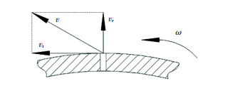
The results indicate that similar phenomena occur in the slinger with other orifices in Fig. 3. When the liquid leaves the orifice, the velocity can be divided into radial velocity vr and tangential velocity vt, as shown in Fig. 7. In most cases, vt significantly exceeds vr, thus vt is the main factor that affects liquid breakage time t'. Increases in vt decrease t', thus it takes shorter time for the liquid to break into the smallest droplets. With increases in vr, the liquid leaves the slinger farther away in radial direction of the slinger per unit time. The radial position of the minimum SMD location corresponds to Y=vr×t'. When the rotary speed increases, vr increases but t' decreases, thus it is not possible to determine the value of Y. On the whole, increases in vr exceed decreases in t', thus the radial coordinate of the minimum SMD location essentially increases when the rotary speed increases.
|
Fig.7 Schematic diagram of liquid velocity direction leaving the orifice of the slinger |
As the mass flowrate increases, vr should increase theoretically, initial droplets formed by the liquid increase, and time t' required for the liquid to break into the smallest droplets increases. Therefore, the location of the minimum SMD should be increased. However, the results indicate that the liquid leaves the orifice in different regimes as shown in Fig. 8. When the rotary speed is very low, the liquid fills the orifice and forms a liquid column, as shown in Regime I in Fig. 8. When the rotary speed increases, the liquid can leave the orifice and form a liquid film around the orifice as shown in Regime II in Fig. 8. The liquid can also accumulate on the orifice side (which is opposite to the slinger rotary direction) and then be thrown out in columns, as shown in Regime III in Fig. 8.

|
Fig.8 Liquid regimes in the orifice |
Changes in the liquid regime directly affect the time when the liquid breaks into the smallest droplets. When the rotary speed is relative low (approximately 3-9 kr/min), the liquid regime typically changes with changes in the rotary speed, thus the minimum SMD location at low rotary speed (3-9 kr/min) is irregular. When the rotational speed is high enough to a certain extent, the liquid regime is typically maintained as constant (it is more likely to form Regime II when the mass flowrate is low and form Regime III when the mass flowrate is large), and the location of minimum SMD varying with the rotary speed becomes regular.
2.2.2.2 Effect of orifice shape on the minimum SMD locationAs shown in Fig. 9, the minimum SMD location of various orifices increases on an overall basis with increases in the rotary speed. However, the minimum SMD location does not exhibit evident regularity at low rotary speeds.

|
Fig.9 Curves of minimum SMD location varying with different orifices (m =6 g/s) |
2.3 Change Rules of SMD/n
The quality of the liquidspray was mainly evaluated by two parameters: SMD and liquid spray distribution index n. In general, the smaller the SMD, the smaller the droplets of the liquid spray; the larger the n, the more uniform the liquid spray. From Section 2.2.1, it is known where the liquid spray SMD is the smallest, the quantity concentration is typically the largest, and the liquid spray evaporation and combustion performance are optimal. The minimum SMD location of the liquid spray changes with changes in the mass flowrate, rotary speed, or orifice shape. When the minimum SMD location changes, the spatial distribution of the liquid spray also changes. Extant studies examined the liquid spray characteristics of the slinger and typically selected a fixed point in the space to measure the spray parameters under different work conditions. Hence, it is not possible to rule out the effect of change in the minimum SMD location on the spatial distribution of the spray. In the test, the spray parameters were measured at a series of points initially and then data were selected at the point where the liquid spray SMD corresponds to the smallest to be analyzed, such that the effect of the change in the minimum SMD location on the spray is removed. Therefore, in the following analysis, all the used data are at the points where SMD is the minimum.
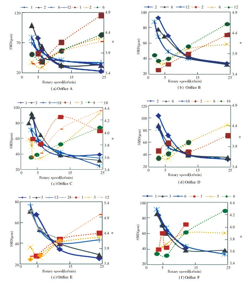
2.3.1 Changes in the rules of SMD/n with rotary speedAs shown in Fig. 10, the results mainly indicate that the liquid spray SMD of each orifice decreases with increases in the rotary speed, and n increases with increases in the rotary speed, thereby indicating that increases in the rotary speed is beneficial to the uniformity of the liquid spray. When the rotary speed is less than 12 kr/min, the effect of changes in the mass flowrate on SMD/n is irregular. When the rotary speed reaches 12 kr/min, the SMD exhibits an overall increase with increases in the mass flowrate, and the degree of the increase decreases with increases in the orifice area. For example, the liquid spray SMD of Orifice C/F with a larger area does not change significantly with increases in mass flowrate although the liquid spray SMD of Orifices A/B/D/E with a smaller area changes significantly with changes in the mass flowrate.
|
Fig.10 Variation in the curves of SMD/n with rotary speed at different mass flowrates (the solid line indicates SMD, the dotted line indicates n, and the number in the legend indicates mass flowrate, unit is g/s) |
When the rotary speed increases, the relative velocity between the liquid and air increases such that the liquid breaks into smaller droplets, and the liquid spray SMD becomes smaller. When the mass flowrate increases, the orifice with large area possesses sufficient space to accommodate the liquid. Liquid regime and radial velocity vr change slightly, thus the change in the degree of the spray SMD is small. The small-area orifices do not possess sufficient space to accommodate the liquid, and liquid regime and vr change significantly, hence the spray SMD changes greatly as well.
2.3.2 Effect of orifice shape on spray SMD/n 2.3.2.1 Contrast at the same mass flowrateAs shown in Fig. 11, with respect to the circular Orifice A/B/C, when the mass flowrate does not exceed 6 g/s, the spray SMD of Orifice A corresponds to the lowest, and the n of Orifice A does not significantly differ from that of Orifice B. Further, Orifice C's spray exhibits the worst atomization uniformity. When the mass flowrate increases to 12 g/s, the spray SMD of Orifice B is smaller than that of Orifice A, and n exceeds that of Orifice A. This indicates that for the circular orifice, the atomization performance of the orifice with a small diameter is better when the mass flowrate is low, and the orifice with a larger diameter exhibits better atomization performance when the mass flowrate increases to a certain extent.

|
Fig.11 Variation in the SMD/n curves with rotary speed for each orifice at the same mass flowrate (the solid line corresponds to SMD, the dotted line corresponds to n, and the alphabet in the legend denotes the orifice number) |
With respect to slot Orifices D/E/F, when the mass flowrate corresponds to 1g/s, the spray SMD of Orifice E is smaller than that of Orifice F, and n exceeds that of Orifice F. However, there is no significant difference in the atomization performances of the two orifices when the mass flowrate increases to 3 g/s. When the flow rate corresponds to 6 g/s, the spray SMD and n value of Orifice D are similar to those of Orifice F, thereby indicating that increases in the width of the slot orifice do not significantly optimize the atomization performance.
With respect to orifices with the same circumference, in Orifices C/E/F, when the mass flowrate corresponds to 1 g/s, the spray SMD of Orifice E is the smallest while the n value of Orifice C is the highest. When the mass flowrate corresponds to 3 g/s, significant differences are absent between the spray SMD of the three orifices although the n of Orifice C is the largest. In Orifices B/D, when the mass flowrate corresponds to 2 and 6 g/s, significant differences are absent between the spray SMD of both orifices although the n value of Orifice B exceeds that of Orifice D on the whole. These results indicate that when the circumference is the same, the spray SMDs of circular and slot orifice are in little difference under different working conditions, and the slot orifice's is slightly smaller than the circular orifice's. However, the uniformity of the circular orifice spray is better than the slot orifice's.
2.3.2.2 Contrast at the same equivalent mass flowrateExtant studies indicated that liquid is thrown out along the circumference of the orifice, and the length of the orifice circumference significantly affects atomization. Let the equivalent mass flowrate be m', and the following expression is obtained:
| $ m^{\prime}=m /P $ |
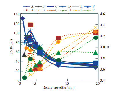
where P denotes the circumference of the orifice. Fig. 12 depicts the relationship between the liquid spray characteristics of each orifice and rotary speed at the same equivalent mass flowrate. As shown in the figure, there are no evident change rules when the rotary speed is less than 12 kr/min. When the rotary speed reaches 12 kr/min, with respect to the circular Orifice A/B/C, the spray SMD of Orifice A is the smallest, and n corresponds to the largest, significant differences are absent between spray SMD/n of Orifices B/C, the spray SMD of Orifice C is smaller while the n of Orifice B is larger. Therefore, it is concluded that increases in the diameter of the orifice does not necessarily lead to better atomization performance in the case where the equivalent mass flowrate is not extremely high.
|
Fig.12 Curves of SMD/n varying with rotary speed for each orifice at the same equivalent mass flowrate (m ′=1/π, the solid line corresponds to SMD, the dotted line corresponds to n, and the alphabet in the legend denotes the orifice number) |
With respect to slot orifices, when the rotary speed is less than 12 kr/min, the spray SMD of Orifice E is the smallest and spray SMD of Orifice D is the largest. When the rotary speed exceeds 12 kr/min, the spray SMDs of the three orifices are similar, and spray SMD of Orifice E is still the smallest although spray SMD of Orifice F corresponds to the largest. The spray distribution index n of the three orifices increases with increases in the rotary speed. When the rotary speed exceeds 12 kr/min, the n of Orifice D corresponds to the smallest, and that of Orifice E is similar to that of Orifice F. The aforementioned findings indicate that increases in the length of the slot improve atomization performance although increases in the width of the slot do not function in the same manner.
The circular orifice was compared with the slot orifice with the same circumference from Orifice B and Orifice D. The results indicate that the spray SMD of Orifice B is smaller than that of Orifice D, while the n exceeds that of Orifice D. Orifice D was compared with Orifice E/F, and the spray SMD sizes of the three orifices were entangled when the rotary speed was less than 12 kr/min. After the rotary speed reached 12 kr/min, the spray SMD of Orifice C corresponded to the smallest and that of F corresponded to the largest. In terms of spray distribution index n, the spray SMD of Orifice C corresponded to the largest and that of Orifice E corresponds to the smallest. The aforementioned results indicate that the atomization performance of the circular orifice exceeds that of the slot orifice with the same circumference when the equivalent mass flowrate of the slinger is the same. With respect to slot orifices, increases in the length of the slot are more favorable for atomization performance than increases in the width.
As shown in Fig. 13, when the equivalent mass flowrate corresponds to 6/π, the size and variation of the liquid spray SMD of the three circular orifices are similar, and the spray SMD of Orifice A is the smallest. The n of Orifice B corresponds to the largest among the three orifices, and the n of Orifice A/C is similar. The results indicate that when the equivalent mass flowrate is the same, the atomization performance of the smaller orifice is better.

|
Fig.13 Variations in the SMD/n curves with rotary speed for each orifice at same equivalent mass flowrate (m′ =6/π, the solid line corresponds to SMD, the dotted line corresponds to n, and the alphabet in the legend denotes the orifice number) |
From the aforementioned analysis in Figs. 11-13, the effect of the orifice shape and size on the atomization performance are as follows:
1) With respect to the circular orifice, at a specific mass flowrate, an optimum diameter d' exists such that when the orifice diameter is d', the liquid spray SMD of the orifice corresponds to the smallest. Additionally, there exists another optimum diameter d″ such that when the orifice diameter is d″, the spray uniformity is optimal. Typically, significant differences are absent between the values of d″ and d', thus it is considered that an optimum diameter exists wherein the orifice exhibits optimal atomization performance at a specific mass flowrate. When the orifice diameter is smaller or larger than the optimum diameter, the spray SMD increases and n decreases. Decreases in the mass flowrate decrease the optimum diameter. The results of the experiment indicate that when the mass flowrate is less than 6 g/s, the atomization performance of the orifice with a diameter of 1 mm is optimal; when the mass flowrate corresponds to 12 g/s, the orifice with a diameter of 2 mm exhibits optimal atomization performance. In practical applications, the mass flowrate of a single orifice is usually less than 6 g/s, thus the diameter of the orifice should not exceed 1 mm.
2) With respect toslot orifices, increases in the length of the slot improve atomization performance although increasing the width does not exhibit significant effect.
3) In most cases, the spray SMD of the slot orifice is slightly smaller than the circular orifice's, but the spray uniformity of the circular orifice is better than the slot orifice's. Overall, the atomization performance of the circular orifice exceeds the slot orifice with a same circumference.
2.3.3 Effect of length of the orifice on spray SMD/nAs shown in Fig. 14, at the mass flowrate of 2 g/s, for circular Orifice B, when the length of the orifice increases, liquid spray SMD increases, and the liquid spray distribution index n increases significantly. With respect to slot Orifice D, when the length of the orifice increases, liquid spray SMD slightly decreases, and the liquid spray distribution index n significantly increases. When the orifice length corresponds to 3 mm, the spray SMD and n of Orifice B exceed those of Orifice D. However, when the length increases to 6 mm, the spray SMD of Orifice D is smaller than that of Orifice B although the n is still smaller than that of Orifice B.

|
Fig.14 Curves of effect of orifice length on spray SMD/n (m =2 g/s, the solid line corresponds to SMD, the dotted line corresponds to n, the alphabet in the legend corresponds to orifice number, and the number in the legend denotes orifice length, unit is mm) |
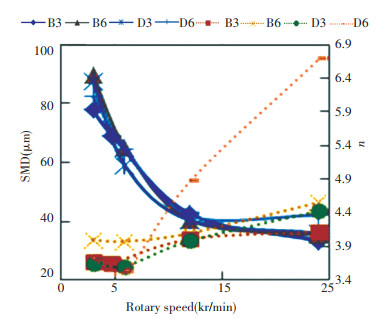
As shown in Fig. 15, when the mass flowrate corresponds to 6 g/s, significant differences are absent in the spray SMDs of Orifice B/D. When the orifice length increases, the spray SMD of Orifice B decreases slightly while n does not significantly change. The spray SMD of Orifice D increases, and the value of n increases significantly. When l=3 mm, the spray SMD of Orifice B is similar to that of Orifice D, and the n of the two orifices is equivalent. When l=6 mm, the spray SMD of Orifice B is smaller than that of Orifice D although the n of Orifice D exceeds that of Orifice B.
|
Fig.15 Curves of effect of orifice length on spray SMD/n (m =6 g/s, the solid line corresponds to SMD, the dotted line corresponds to n, the alphabet in the legend denotes orifice number, and the number in the legend denotes orifice length, unit is mm) |
It can be concluded that at different mass flowrates, the atomization performance of circular orifice changes differently from that of slot orifice with the same circumference when the orifice length changes. When the orifice length increases, the liquid spray SMD increases on an overall basis although the uniformity of the spray significantly improves. Therefore, in the case where the liquid spray SMD can satisfy the design requirements, the orifice length is appropriately increased to improve uniformity of the liquid spray.
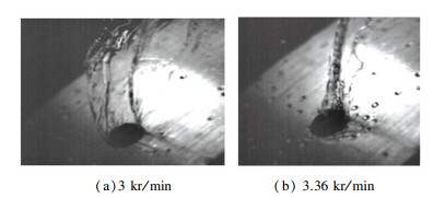
2.3.4 Effect of liquid regime in the orifice on atomization performanceAs shown in Fig. 8, the liquid leave the orifice in various regimes, and different initial liquid regimes break into the droplets with different diameter distributions via primary atomization and then affect final liquid spray SMD and n. However, in general, the liquid regime in the orifice is related to the mass flowrate and the rotary speed. When the mass flowrate or rotary speed changes, it is not possible to quantitatively examine the effect of the liquid regime in the orifice on the atomization performance. In the test, the results indicate that in Orifice C, when the rotary speed corresponds to 3.3 kr/min, the mass flowrate corresponds to 3 g/s, and the liquid regime in the orifice corresponds to Regime II. However, when the rotary speed increases to 3.36 kr/min, the liquid regime suddenly changes to Regime III, as shown in Fig. 16. The rotary speed of the aforementioned two cases is almost the same, thus they can be used to examine the effect of the liquid regime on atomization performance.
|
Fig.16 Pictures of liquid regimes in Orifice C |
As shown in Fig. 17, when the rotary speed increases from 3.3 kr/min to 3.36 kr/min, the spray SMD suddenly decreases from 92 μm to 87 μm, and the value of n suddenly increases from 3.77 to 3.88. As the change in rotary speed is insignificant, it proves that changes in liquid regime causes changes in the liquid spray. The results indicate that the spray SMD of Regime III is smaller than that of Regime II, and the spray uniformity of Regime III exceeds that of Regime II. Given that only one case exists, these conclusions cannot be considered a general law.

|
Fig.17 Curves of effect of different morphologies on spray SMD/n (Orifice C, m =3 g/s, the solid line denotes SMD, the dotted line denotes n) |
2.3.5 Effect of liquid surface tension on spray SMD/n
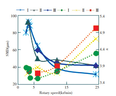
As shown in Fig. 18, when the rotary speed does not exceed 6 kr/min, decreases in liquid surface tension decrease liquid spray SMD although n changes irregularly. However, when the rotary speed exceeds 12 kr/min, the liquid spray SMD of Solution I with the largest surface tension corresponds to the smallest, significant differences are absent between spray SMD of Solution II and III, and liquid spray uniformity of the Solution III is optimal.
|
Fig.18 Curves of effect of liquid surface tension on spray SMD/n (Orifice C, m =3 g/s, the solid line denotes SMD, the dotted line denotes n, and the legend denotes solution type) |
Theoretically, decreases in the liquid surface tension decrease droplets such that the liquid breaks under the same conditions. However, from Section 2.3.4, the liquid regime in the orifice also significantly affects atomization. When the surface tension of the liquid decreases, it is probable that the liquid regime in the orifice also changes, thus the liquid spray SMD no longer decreases when liquid surface tension decreases.
3 ConclusionsIn this study, experimental research was conducted. The results indicated that the location of the spray minimum SMD of the slinger changes with changes in the mass flowrate and rotary speed. Accordingly, liquid spray characteristics were measured at a series of points in the slinger's radial direction and the data were selected where the spray SMD denotes the smallest to be analyzed, which were compared with the traditional method of measuring the liquid spray characteristics of the slinger at a fixed location. Droplet size and uniformity of the liquid spray correspond to two important criteria for evaluating the slinger atomization performance. Therefore, liquid spray SMD and distribution index n are mainly used for the analysis:
1) On the whole, the distribution index n increases with increasing rotary speed. Changes in the spray SMD of the orifice with a smaller area exceed those of the orifice with a larger area when the mass flowrate changes.
2) An optimum diameter exists for the orifice when the mass flowrate is fixed. The spray SMD of the orifice with the optimum diameter denotes the lowest, and the spray distribution index n denotes the highest. The optimum diameter increases with increases in flowrate.
3) Increases in the length of orifice improve spray uniformity although the spray SMD also simultaneously increases.
4) With respect to slot orifices, increases in the length of slot decrease liquid spray SMD although widening the width of the slot does not significantly affect the atomization.
5) The spray distribution index n of the circular orifice exceeds that of the slot orifice on the whole.
6) The liquid regime in the orifice significantly affects the atomization of the slinger. When the liquid surface tension decreases, the liquid regime in the orifice also changes simultaneously, thus the liquid spray SMD does not strictly decrease with the decreases in surface tension.
When designing a slinger, the parameters of the orifice should be determined according to the actual work condition of the slinger. If the orifice is round, the diameter of the orifice should be near the optimum diameter; if the orifice is slot, lengthening the orifice is beneficial to the atomization.
| [1] |
Lefebvre A. Fifty years of gas turbine fuel injection. Atomization and Sprays, 2000, 10(3-5): 251-276. DOI:10.1615/AtomizSpr.v10.i3-5.40 (  0) 0) |
| [2] |
Lefebvre A H P U. Atomization and Sprays. New York: Hemisphere Publishing, 1989.
(  0) 0) |
| [3] |
Maskey H C, Marsh F X. The Annular Combustion Chamber with Centrifugal Fuel Injection. New York: SAE International, 1962. DOI:10.4271/620007
(  0) 0) |
| [4] |
Morishita T. Adevelopment of the fuel atomizing device utilizing high rotational speed. ASME 1981 International Gas Turbine Conference and Products Show. New York: ASME, 1980. 1-6. DOI: 10.1115/81-GT-180.
(  0) 0) |
| [5] |
Dahm W J A, Patel P R, Lerg B H. Experimental visualizations of liquid breakup regimes in fuel slinger atomization. Atomization and Sprays, 2006, 16(8): 933-944. DOI:10.1615/AtomizSpr.v16.i8.50 (  0) 0) |
| [6] |
Dahm W J A, Patel P R, Lerg B H. Fundamental analysis of liquid atomization by fuel slingers in small gas turbines. Proceedings of the 32nd AIAA Fluid Dynamics Conference and Exhibit. Reston, VA: AIAA, 2002. AIAA 2002-3138. DOI: 10.2514/6.2002-3183.
(  0) 0) |
| [7] |
Dahm W J A, Patel P R, Lerg B H. Analysis ofliquid breakup regimes in fuel slinger atomization. Atomization and Sprays, 2006, 16(8): 945-962. DOI:10.1615/AtomizSpr.v16.i8.60 (  0) 0) |
| [8] |
Sescu C, Kucinschi B R, Afjeh A A, et al. Experimental test rig with results on liquid atomization by slinger injectors. Journal of Engineering for Gas Turbines and Power, 2011, 133(11): 114505. DOI:10.1115/1.4003790 (  0) 0) |
| [9] |
Sescu C, Kucinschi B R, Sescu A. Computational analysis of a slinger atomizer. Porceedings of the 46th AIAA/ASME/SAE/ASEE Joint Propulsion Conference & Exhibit. Reston, VA: AIAA, 2010. AIAA 2010-6581. DOI: 10.2514/6.2010-6581.
(  0) 0) |
| [10] |
Sescu C, Kucinschi B R, Abdollah A A, et al. Experimental test rig with results on atomization by slinger injectors. Journal of Engineering for Gas Turbines and Power, 2011, 133: 114505. DOI:10.1115/1.4003790 (  0) 0) |
| [11] |
Sescu C, Kucinschi B, Afjeh A, et al. Parametric study of liquid atomization by slinger injectors. Proceedings of the 45th AIAA/ASME/SAE/ASEE Joint Propulsion Conference & Exhibit. Reston, VA: AIAA, 2009. AIAA 2009-4829. DOI: 10.2514/6.2009-4829
(  0) 0) |
| [12] |
Choi S M, Jang S H. Spraybehavior of the rotary atomizer with in-line injection orifices. Atomization and Sprays, 2010, 20(10): 863-875. DOI:10.1615/AtomizSpr.v20.i10.30 (  0) 0) |
| [13] |
Choi S M, Jang S H, Lee D H, et al. Spray characteristics of the rotating fuel injection system of a micro-jet engine. Journal of Mechanical Science and Technology, 2010, 24(2): 551-558. DOI:10.1007/s12206-009-1206-6 (  0) 0) |
| [14] |
Choi S M, Yun S, Jeong H J, et al. Spatialdrop behavior of a rotary atomizer in a cross flow. Atomization and Sprays, 2012, 22(12): 1077-1095. DOI:10.1615/AtomizSpr.2013007146 (  0) 0) |
| [15] |
Choi S M, Yun S, Jeong H J, et al. Spray incross flow of a rotary atomizer. Atomization and Sprays, 2012, 22(2): 143-161. DOI:10.1615/AtomizSpr.2012005049 (  0) 0) |
| [16] |
Jia W D, Li P P, Qiu B J, et al. Application of phase doppler droppler particle analyzer in reek spray nozzles characteristic experiment. China Rural Water and Hydropower, 2008, 9: 70-72. (  0) 0) |
 2021, Vol. 28


