2. Collaborative Innovation Center of Advanced Aero-Engine, Beijing 100191, China;
3. Beijing Engineering Technological Research Center of High-Efficient and Green CNC, Machining Process and Equipment, Beijing 100191, China;
4. Beijing Aerospace Petrochemical Technology and Equipment Engineering Limited Corporation, Beijing 100166, China
Titanium alloys are utilized extensively in aerospace and related engineering fields because of their high strength to weight ratio maintained at elevated temperature, good fatigue resistance, and excellent corrosion resistance[1]. Despite the increasing usage and outstanding qualities of titanium alloys, the poor machinability is still a well-known attribute because of their low elasticity modulus and thermal conductivity[2]. Major improvements in machining titanium alloys usually come from the evolution of new tool materials. In the past few decades, remarkable progress of cutting tool materials have been made in tool materials, including cemented carbides, ceramics, cubic boron nitride, and diamond. Nowadays, when machining titanium alloys, the polycrystalline diamond (PCD)[3-6] and coated cemented carbides[7-9] are the most widely used. In addition, PCD tools are relatively expensive in industry practice, so coated carbide tools are the most reasonable choice for machining titanium alloys[10]. Dearnley and Grearson[11] studied the wear morphologies based on 16 kinds of cemented carbide tools with/without coatings and 6 kinds of ceramic tools for machining Ti-6Al-4V alloys. It turned out that straight grade cemented carbides were the most appropriate tool materials in industrial production when machining titanium alloys.
Uncoated cemented carbide tools show better performance than the coated ones with Ti under certain conditions, which has been widely confirmed by many researchers. Dearnley and Grearson[11] found that cemented carbide tools with coatings of TiN, TiC, Al2O3, and HfN wear more rapidly on the rake and flank face than the uncoated cemented carbide tools. Hou et al.[12] pointed out that TiN/TiAlN coated cemented carbide tools showed poor performance in higher cutting speeds. The mean temperature of the flank of coated tools increased with the increase of cutting speeds, while the uncoated cemented carbide tools almost remained constant when the cutting speed exceeded 125.6 m/min. However, some other researchers suggested that coated cemented carbide tools with Ti content receive a better result in machining different titanium alloys. Chang and Lai[13] confirmed that the flank wear of uncoated cemented carbide tools showed the fastest rate among four kinds of uncoated and coated tools when the cutting speeds were 150 m/min and 350 m/min. Zuo et al.[14] concluded that PVD-TiN+TiAlN coatings had the best performance compared with CVD-coated and uncoated tools in milling TA19 alloys because of the smallest cutting force and wear quantities.
Admittedly, when machining titanium alloys, abrasion, adhesion, plastic deformation, and fatigue are the main wear mechanisms of the uncoated cemented carbide tools. The dominant one turns out to be adhesion resulting from dissolution-diffusion. Venugopal et al.[15] studied the wear behaviors of uncoated cemented carbide when machining Ti-6Al-4V alloys under dry, wet, and cryogenic cooling environments. The SEM investigation revealed that adhesion occurred under all machining conditions. Vargas Pérez[16] focused on the wear mechanisms of coarse and fine WC grain inserts during milling of γ-TiAl alloys. It shows that the wear mechanisms of the WC inserts were abrasion, adhesion, and fatigue. Che Haron et al.[17] researched the performance of uncoated carbide tools and coated carbide tools containing Ti in the coatings in dry milling Ti-6242S. The results observed on both tools showed that adhesion (attrition) and dissolution-diffusion were the main wear mechanisms. Niu et al.[18] compared the performance of PVD-coated with CVD-coated carbide inserts in face milling TC6 alloy, and concluded that the PVD-coated carbide inserts shared the same wear mechanisms with the CVD-ones except for the chipping phenomenon. Bordin et al.[19] studied the wear mechanisms of coated cemented carbide inserts when semi-finishing EBM Ti-6Al-4V alloys were under dry and cryogenic conditions. The results showed that adhesive wear was the major wear mechanism under both dry and cryogenic condition. Lv et al.[20] surveyed the tool wear of Ti(C, N)-Al2O3 coated cemented carbide tools in milling Ti40 using pneumatic mist jet impinging cooling. It turned out that the main wear mechanisms were abrasion and adhesion.
Surprisingly, the current cutting tools suggested by several famous tool producers to machine titanium alloys are all cemented carbide tools with Ti in the coatings. However, as Ezugwu and Wang[1] and Jaffery and Mativenga[2] have claimed that cemented carbide tools containing Ti in the coatings show high solubility and affinity to titanium alloys so that they are not appropriate choice for machining titanium alloys. This contradiction between practice and theory in the applicability of cemented carbide tools with Ti in the coatings in machining titanium alloys has attracted many scholars, but only a few articles have been published to systematically explain the contradiction.
In this paper, the contradiction between the high affinity of cemented carbide tools containing Ti in the coatings and its wide usage in machining titanium alloys will be theoretically and experimentally analyzed. Moreover, the analysis of molecular thermodynamics based on diffusion wear will be carried out to explain the operating principles of cemented carbide tools containing Ti in the coatings during machining titanium alloys. The four kinds of cemented carbide tools and another two kinds of cermet tools with/without Ti coatings were used to verify the contradiction mentioned above. All of these works can be used to give useful suggestions on how to choose cemented carbide tools for machining titanium alloys.
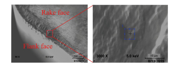
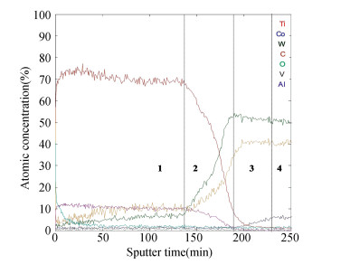
1 Experimental DesignIn order to analyze the diffusion process between the cutting tools and workpiece, experiments were carried out. The cutting tools used in this experiment was KW10, and the workpiece material was Ti-6Al-4V alloy. The experimental parameters are shown in Table 1. Then the tool-chip compositions were sampled at a small area (length: 5 μm; width: 5 μm) of the crater wear region, which were analyzed by auger electron spectroscopy (AES) with PHI-700 of ULVAC-PHI in Japan. Compared with the traditional process of the wire-electrode cutting, AES introduces less error of the composition. The schematic diagram of AES is shown in Fig. 1(a), the schematic diagram of sampling region is shown in Fig. 1(b), and the working process is shown in Fig. 1(c). The actual sampling location and the analyzed result is shown in Fig. 2 and Fig. 3.
| Table 1 Cutting parameters used for this experiment |

|
Fig.1 Schematic diagram of the auger electron spectroscopy analysis |
|
Fig.2 Position and direction of the auger electron spectroscopy analysis |
|
Fig.3 Result of the auger electron spectroscopy analysis for built-up-layer |
2 Results and Discussions 2.1 Analysis of the Diffusion Wear Based on the AES
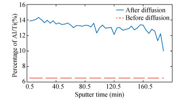
As is known, atom diffusion is an irregular process. However, it presents in the direction from high concentration to low concentration. Diffusion capacity can be characterized by diffusion distance. In the unit time, the longer the elements diffuse, the better the diffusion capacity is[21]. In this study, the AES used relative thermal oxidation SiO2/Si for detection with a nominal sputtering rate of 30 nm/min. So the "sputter time" in Fig. 3 and Fig. 4 actually refers to the diffusion distance. Therefore, Fig. 3 can be divided into four zones according to the diffusion distance. Zone 1 represents the region of cutting chip or built-up-layer, Zone 2 represents transition layer, and Zones 3 and 4 represent the tool substrate.
|
Fig.4 The mass ratio of Al atom to Ti atom before/after diffusion process |
As also shown in Fig. 3, the concentration of W (tungsten) atom at the intersection of Zones 2 and 3 is higher than that at the tool substrate. However, the concentration of C atoms decreased by nearly 10% compared with the tool substrate. Meanwhile, the diffusion of Co atoms occurred at Zone 4. The results indicate that the diffusion coefficient was in the order of Co > C > W for the tool substrate material.
Al atoms have similar atomic activity but slightly smaller atomic radius than Ti atoms. Therefore, Al atoms can easily replace Ti atoms and change the lattice constant of titanium alloys. Theoretically speaking, the diffusion coefficient of Al atoms is higher than the Ti atoms under the same conditions, and the diffusion depth of the Al atoms should be deeper than that of the Ti atoms. In fact, the diffusion depth of the Ti atoms is deeper than that of the Al atoms as shown in Zone 3, which is due to the far greater concentration of the Ti atoms compared with the diffusion depth of the Al atoms. Meanwhile, the mass ratio of the Al atoms to the Ti atoms is less than 7% according to material composition ratio of the Ti-6Al-4V workpiece. However, this ratio is close to 15% at built-up edge surface as shown in Fig. 4. It can be concluded that the Al atoms are indeed enriched out to the surface driven by thermoelectric effect.
Fig. 3 shows that high concentration of the Al atoms and O atoms appeared at the surface of built-up-layer, and then Al2O3 might be generated, because the Al atoms were oxidized more easily than Ti atoms. However, the concentration of O atoms was very low at the transition layer, which means oxidation reaction would not occur at the tool substrate. It could be inferred that oxidation wear should not be one of the main wear mechanisms for cemented carbide tools when machining titanium alloys.
Ti and C should exist in the form of TiC, while W and C exist in the form of WC1-x. It could be known from the diffusion curves of the W and C atoms at Zones 1 and 2 in Fig. 3 that a large amount of W and C atoms were spread out from tool substrate to built-up-layer, while the Ti atoms could hardly be spread out from the built-up-layer to the tool substrate, because the concentration of Ti atoms at Zone 3 was very low. Therefore, WC1-x could be easily dissolved in TiC, while TiC could hardly be dissolved in WC, as was also proved by Yang et al.[22]
Based on the analysis mentioned above, it could be concluded that dissolution-diffusion wear was one of the main wear mechanisms for the cemented carbide tools when titanium alloys were machined, and the main reason for the diffusion wear was still the mutual diffusion of Ti/Co atoms, leading to deterioration of the tool substrate. The tool materials would then be torn apart from their substrate as the built-up-layer was taken away.
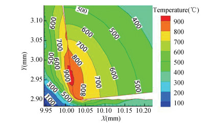
2.2 Analysis of the Diffusion Wear Based on the Molecular ThermodynamicsIn order to further analyze the Ti/Co diffusion behavior, molecular dynamics simulation was carried out in Materials Studio under the temperature and pressure as shown in Table 2 at the second deformation zone (Fig. 5)[23]. The cutting simulation in Fig. 5 was obtained by the simulations in AdvantEdge whose cutting parameters are shown in Table 2. The tool and workpiece materials were installed with the standard material database of the software. The cutting tool material was M kind of cemented carbide. The environment temperature of the simulation was set up at 25 ℃ and the fracture criterion of tool is brittle rupture. The solution process is thermodynamic coupling.
|
Fig.5 Simulation of the cutting temperature of carbide cemented tools when machining Ti-6Al-4V alloys ( v=120 m/min, f =0.05 mm/r, ap=1.5 mm) |
| Table 2 Cutting parameters used in AdvantEdge simulation for specific cutting temperature and pressure in the second deformation zone |
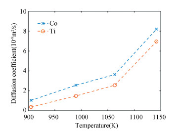
In the molecular dynamic simulation, Co atoms and Ti atoms both have simple hexagonal crystal structures. During modeling, they were put into the simulated box, and there was no gap between the two interfaces. Periodic boundary conditions were applied in all directions of the model to eliminate the boundary effect. In the process of the simulation, isothermal isobaric ensemble was adopted. The diffusion coefficient of Ti/Co was obtained, as shown in Fig. 6.
|
Fig.6 Relative molecular diffusion coefficient of Ti/Co atoms |
It was obvious that the diffusion rate of Co atoms was greater than that of Ti atoms, which was in good agreement with the result in Fig. 3. It indicates that the cemented carbide tools containing Ti in the coatings could reduce the concentration gradient of the Ti atoms between the tools and workpiece, thus reducing the diffusion of Ti atoms to the tool substrate. But it had little influence on the diffusion rate of the Co atoms into the chips, which is why diffusion wear occurs when cemented carbide tools are used to machine titanium alloys.
For the cemented carbide tools containing Ti in the coatings, especially at high cutting speeds, the binding force between WC crystal grains was weakened due to the diffusion and reduction of the Co atoms in the tool substrate, resulting in the reduction of the binding force between the WC and TiC. Meanwhile, as proved by Jawaid et al.[24], the diffusion of Co atoms from cemented carbide tools led to the decrease of the bonding strength of cemented carbide particles. Due to the affinity of the same element Ti in chip and TiC in tool coatings, adhesive wear was more likely to occur[25-26]. With the increase of adhesive layer and the relative sliding, the adhesive layer was bound to be fallen off, causing the cutting tool substrate to be torn. Therefore, the cemented carbide tools with Ti in the coatings were not fit for cutting titanium alloys. Nevertheless, from the perspective of the molecular thermodynamics, molecular diffusion rate of the Ti/Co atom was nonlinearly positively correlated with cutting temperature. If the critical point of abrasive, adhesive, and diffusion wear could be found, cemented carbide tools containing Ti in the coatings may have better performance under the corresponding cutting conditions such as low cutting speeds and fine cooling.
3 Verification and Discussions 3.1 Design of Verification ExperimentsIn order to verify the conclusion that the cemented carbide tools with Ti in the coatings are not appropriate in machining titanium alloys, a solid bar of Ti-6Al-4V alloy workpiece with a diameter of 50 mm and a length of 200 mm was turned using four kinds of cemented carbide inserts and another two kinds of cermet inserts (Table 3) at a hydrostatic spindle CA6140 lathe under dry conditions. KW10-A and KW10-B were coated cemented carbide inserts made on the substrate of KW10 by the authors, and the other four types of inserts were supplied by Kyocera. The cermet inserts TN6020 and PV90 were used to further verify the high affinity of cutting tools containing Ti in the substrate/coating when machining titanium alloys. All the inserts were mounted on a tool holder. The cutting length was kept between 95 mm and 100 mm, and the cutting inserts mounted on a tool holder (ZCCCT CSRNR2525M12) generated specific cutting geometric angles as shown in Table 4. Meanwhile, the cutting parameters was also listed in Table 4.
| Table 3 Material information and geometric code of the six kinds of inserts |
| Table 4 Geometric angle and cutting parameters used in the verification experiments |
3.2 Discussions of the Verification Experiments
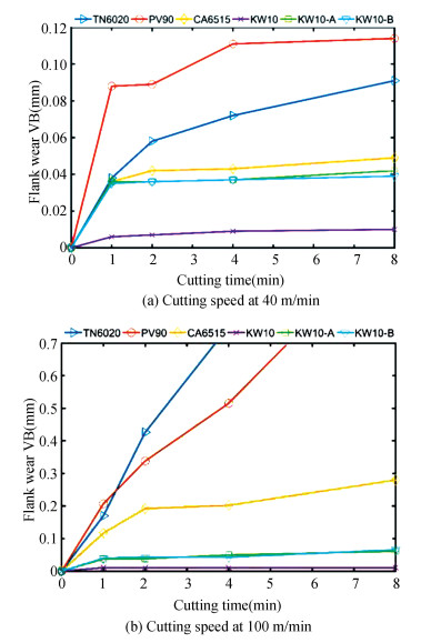
The flank wear width (VB) was measured at the different cutting time (Table 4) as shown in Fig. 7. In order to verify the major wear mechanisms of the worn inserts, wear topographies (Figs. 8-9) were measured by a laser scanning confocal microscope OLS4100 of OLYMPUS in Japan.
|
Fig.7 Flank wear VB against cutting time at different cutting speeds |

|
Fig.8 Flank wear morphologies at 40 m/min |

|
Fig.9 Flank wear morphologies at 100 m/min |
It could be observed from Fig. 7 that the VB of the KW10-A and KW10-B was larger than that of the KW10, indicating that the KW10 tool showed better wear resistance compared with the KW10-A and KW10-B at 40 or 100 m/min. As mentioned above, the only difference among KW10, KW10-A, and KW10-B is that both KW10-A and KW10-B were processed to form a layer of Ti coatings. Therefore, both the KW10-A and KW10-B had a bad resistance due to the high affinity of the same element Ti in the chip and TiC in the coating, so it could be verified that the cemented carbide tools with Ti in the coatings were not suitable for machining the titanium alloy. The VB of the TN6020 and PV90 was larger than that of the KW10. Meanwhile, as shown in Figs. 8-9, adhesive layers at the flank surface of the TN6020 and PV90 were much more obvious than that of the KW10, all of which was caused by the high affinity of the same element Ti in chip and TiC in tool substrate mentioned above. Therefore, it could also be verified that the cutting tools with Ti in the substrate are not suitable for machining the titanium alloys.
The wear resistance was compared among KW10-A, KW10-B, and CA6515. Generally, the wear resistance of TiAlSiN coatings was much better than that of TiAlN coatings. However, the VB of KW10-A and KW10-B was nearly equal as shown in Fig. 7. Moreover, KW10-A performed better in wear resistance than CA6515. Table 3 shows that the coating compositions of KW10-A and CA6515 were almost the same, but the substrate hardness of KW10-A matrix was slightly higher than that of CA6515 matrix. Therefore, it was the performance of a tool substrate rather than a coating that could represent the wear resistance of a tool.
Comparison of Fig. 7(a) and (b) shows that the VB of CA6515 at 100 m/min was larger than that of the CA6515 at 40 m/min. Therefore, the cemented carbide tools with Ti coatings were more suitable for machining Titanium alloys at lower cutting speed. As is known to all, the cutting temperature increased with the growth of the cutting speed. Therefore, under the lower temperature and cutting speeds, the high hardness and low thermal conductivity of coating enhanced the wear resistance and delayed diffusion wear of tool substrate. However, under higher temperature and cutting speeds, a large probability of thermal cracking followed by coating delamination would happen due to the mismatch in the coefficients of thermal expansion and uneven thermal stress field. Fortunately, at a steady cutting state, geometric gradient microstructure resulting from coating delamination reduced cutting force, and decreased the heat generated by the contact friction with reduced tool-chip contact area. Therefore, the cemented carbide tools containing Ti in the coatings could be used for machining titanium alloys only on the condition that the cutting parameters were relatively reasonable, for example, at relatively low cutting speed and temperature.
Comparison of the wear situations as shown in Fig. 7(a) and (b) demonstrates that the TN6020 inserts showed better wear resistance compared with the PV90 inserts at the initial wear stage, which contributed to the fact that the surface hardness of TiCN was higher than that of TiN when the early cutting temperature was low. However, the wear resistance of the TN6020 inserts was worse than that of the PV90 inserts with further increase of cutting time. As is mentioned above, cutting temperature increased with the growth of the cutting speed. A large amount of cutting heat gathered at the tool surface for their low thermal conductivity, decreasing to high surface hardness of TiCN. Meanwhile, Fernandes et al.[27] claimed that the NbC in the substrate increased the wear resistance at high temperature of the substrate, so the PV90 inserts had better wear resistance at relatively high cutting speed compared with the TN6020 inserts.
4 ConclusionsIn order to give a better theoretical and experimental explication on the contradiction of the cutting tools containing Ti in machining titanium alloys, four kinds of cemented carbide tools with/without Ti coatings and another two types of cermet tools were used for turning Ti-6Al-4V alloys at different cutting parameters. The conclusions could be listed as follows:
1) The general cutting tools containing Ti in the substrate/coatings are not appropriate choice for machining titanium alloys. In particular, the cemented carbide tools containing Ti in the coatings are not suitable for machining titanium alloys. But the cemented carbide tools containing Ti in the coatings had better wear resistance only on the condition that the cutting parameters are relatively reasonable, such as at relatively low cutting speed and temperature, when machining titanium alloys.
2) Dissolution-diffusion wear was one of the major wear mechanisms for the cemented carbide tools containing Ti in the substrate/coatings when titanium alloys were machined at high cutting speeds, and the main cause for the diffusion wear is still the mutual diffusion of Ti/Co atoms. Meantime, oxidation wear should not be the main wear mechanisms for the cemented carbide tools when machining titanium alloys.
3) The wear resistance of a cemented carbide tool is mainly related to the performance of the tools' substrate other than the tools' coatings when machining titanium alloys.
| [1] |
Ezugwu E O, Wang Z M. Titanium alloys and their machinability-a review. Journal of Mateirials Processing Technology, 1997, 68(3): 262-274. DOI:10.1016/S0924-0136(96)00030-17 (  0) 0) |
| [2] |
Jaffery S H I, Mativenga P T. Wear mechanisms analysis for turning Ti-6Al-4V—towards the development of suitable tool coatings. The Internation Journal of Advanced Manufacturing Technology, 2012, 58(5-8): 479-493. DOI:10.1007/s00170-011-3427-y (  0) 0) |
| [3] |
da Silva R B, MacHado Á R, Ezugwu E O, et al. Tool life and wear mechanisms in high speed machining of Ti-6Al-4V alloy with PCD tools under various coolant pressures. Journal of Materials Processing Technology, 2013, 213(8): 1459-1464. DOI:10.1016/j.jmatprotec.2013.03.008 (  0) 0) |
| [4] |
Ji W, Liu X L, Wang L H, et al. Experimental evaluation of polycrystalline diamond (PCD) tool geometries at high feed rate in milling of titanium alloy TC11. The International Journal of Advanced Manufacturing Technology, 2015, 77(9-12): 1549-1555. DOI:10.1007/s00170-014-6517-9 (  0) 0) |
| [5] |
Pan W C, Ding S L, Mo J. Thermal characteristics in milling Ti6Al4V with polycrystalline diamond tools. The International Journal of Advanced Manufacturing Technology, 2014, 75(5-8): 1077-1087. DOI:10.1007/s00170-014-6094-y (  0) 0) |
| [6] |
Li G X, Rahim M Z, Ding S L, et al. Performance and wear analysis of polycrystalline diamond (PCD) tools manufactured with different methods in turning titanium alloy Ti-6Al-4V. The International Journal of Advanced Manufacturing Technology, 2016, 85(1-4): 825-841. DOI:10.1007/s00170-015-7949-6 (  0) 0) |
| [7] |
Nouari M, Ginting A. Wear characteristics and performance of multi-layer CVD-coated alloyed carbide tool in dry end milling of titanium alloy. Surface and Coatings Technology, 2006, 200(18-19): 5663-5676. DOI:10.1016/j.surfcoat.2005.07.063 (  0) 0) |
| [8] |
Ghani J A, Haron C H C, Hamdan S H, et al. Failure mode analysis of carbide cutting tools used for machining titanium alloy. Ceramics International, 2013, 39(4): 4449-4456. DOI:10.1016/j.ceramint.2012.11.038 (  0) 0) |
| [9] |
Sun S J, Brandt M, Mo J P T. Evolution of tool wear and its effect on cutting forces during dry machining of Ti-6Al-4V alloy. Proceedings of the Institution of Mechanical Engineers, Part B: Journal of Engineering Manufacture, 2014, 228(2): 191-202. DOI:10.1177/0954405413500243 (  0) 0) |
| [10] |
Li A H, Zhao J, Hou G M. Effect of cutting speed on chip formation and wear mechanisms of coated carbide tools when ultra-high-speed face milling titanium alloy Ti-6Al-4V. Advances in Mechanical Engineering, 2017, 9(7): 1-13. DOI:10.1177/1687814017713704 (  0) 0) |
| [11] |
Dearnley P A, Grearson A N. Evaluation of principal wear mechanisms of cemented carbides and ceramics used for machining titanium alloy IMI 318. Materials Science Technology, 1986, 2(1): 47-58. DOI:10.1179/mst.1986.2.1.47 (  0) 0) |
| [12] |
Hou J Z, Zhou W, Duan H J, et al. Influence of cutting speed on cutting force, flank temperature, and tool wear in end milling of Ti-6Al-4V alloy. The International Journal of Advanced Manufacturing Technology, 2014, 70(9-12): 1835-1845. DOI:10.1007/s00170-013-5433-8 (  0) 0) |
| [13] |
Chang Y Y, Lai H M. Wear behavior and cutting performance of CrAlSiN and TiAlSiN hard coatings on cemented carbide cutting tools for Ti alloys. Surface and Coatings Technology, 2014, 259(B): 152-158. DOI:10.1016/j.surfcoat.2014.02.015 (  0) 0) |
| [14] |
Zuo D W, Huang C Z, Chen M, et al. Wear behavior of carbide inserts in face milling TA19 alloy. Advanced Materials Research, 2012, 426: 339-343. DOI:10.4028/www.scientific.net/AMR.426.339 (  0) 0) |
| [15] |
Venugopal K A, Paul S, Chattopadhyay A B. Growth of tool wear in turning of Ti-6Al-4V alloy under cryogenic cooling. Wear, 2007, 262(9-10): 1071-1078. DOI:10.1016/j.wear.2006.11.010 (  0) 0) |
| [16] |
Vargas Pérez R G. Wear mechanisms of WC inserts in face milling of gamma titanium aluminides. Wear, 2005, 259(7-12): 1160-1167. DOI:10.1016/j.wear.2005.02.062 (  0) 0) |
| [17] |
Che Haron C H, Ginting A, Arshad H. Performance of alloyed uncoated and CVD-coated carbide tools in dry milling of titanium alloy Ti-6242S. Journal of Materials Processing Technology, 2007, 185(1-3): 77-82. DOI:10.1016/j.jmatprotec.2006.03.135 (  0) 0) |
| [18] |
Niu Q L, Chen M, Ming W W, et al. Evaluation of the performance of coated carbide tools in face milling TC6 alloy under dry condition. The International Journal of Advanced Manufacturing Technology, 2013, 64(5-8): 623-631. DOI:10.1007/s00170-012-4043-1 (  0) 0) |
| [19] |
Bordin A, Bruschi S, Ghiotti A, et al. Analysis of tool wear in cryogenic machining of additive manufactured Ti6Al4V alloy. Wear, 2015, 328-329: 89-99. DOI:10.1016/j.wear.2015.01.030 (  0) 0) |
| [20] |
Lv D S, Xu J H, Ding W F, et al. Tool wear in milling Ti40 burn-resistant titanium alloy using pneumatic mist jet impinging cooling. Journal of Materials Processing Technology, 2016, 229: 641-650. DOI:10.1016/j.jmatprotec.2015.10.020 (  0) 0) |
| [21] |
Chen H, Rushworth A, Hou X, et al. Effects of temperature on the β-phase depletion in MCrAlYs: a modelling and experimental study towards designing new bond coat alloys. Surface and Coatings Technology, 2019, 363(2): 400-410. DOI:10.1016/j.surfcoat.2019.02.024 (  0) 0) |
| [22] |
Yang J G, Tan D Q, Chen H. Cemented Carbide. Changsha, China: Central South University Press, 2012: 249-293.
(  0) 0) |
| [23] |
Du D X, Sun J F, Yang S, et al. An investigation on measurement and evaluation of tool wear based on 3D topography. International Journal of Manufacturing Research, 2018, 13(2): 168-182. DOI:10.1504/IJMR.2018.093263 (  0) 0) |
| [24] |
Jawaid A, Sharif S, Koksal S. Evaluation of wear mechanisms of coated carbide tools when face milling titanium alloy. Journal of Materials Processing Technology, 2000, 99(1): 266-274. DOI:10.1016/S0924-0136(99)00438-0 (  0) 0) |
| [25] |
Li Y S. Study on chemical property matching of cemented carbide tool with Ti-6Al-4V titanium Alloy. Jinan: Shandong University, 2010. 65-120.
(  0) 0) |
| [26] |
Ezugwu E O, Bonney J, Yamane Y. An overview of the machinability of aeroengine alloys. Journal of Materials Processing Technology, 2003, 134(2): 233-253. DOI:10.1016/S0924-0136(02)01042-7 (  0) 0) |
| [27] |
Fernandes F A P, Gallego J, Picon C A, et al. Wear and corrosion of niobium carbide coated AISI 52100 bearing steel. Surface and Coatings Technology, 2015, 279: 112-117. DOI:10.1016/j.surfcoat.2015.08.036 (  0) 0) |
 2021, Vol. 28


