2. Harbin Institute of Technology, School of Mechatronics Engineering, Harbin 150001, China
The safe transportation of satellite is a key process of satellite assembly. Generally, the structure of communication satellite and navigation satellite are based on central cylinder, so the horizontal transportation of satellite makes no unexpected effect on their structure. However, the structure of most remote sensing satellites are not based on central cylinder for various satellite payload, and the specific structure causes lower strength[1-6]. In the past, most of large-scale remote sensing satellites used the method of transporting service module (SM) and payload module (PM) separately. After the satellite is transported to launch site, the SM and PM are assembled and the final test is completed. With the growth of satellite launch missions in recent years, in order to shorten the test period of AIT in launch site, more and more remote sensing satellite transportation choose to use this method in overall transportation mode. By this way, satellite assembly efficiency is greatly improved. However, during the transportation, due to the fact that satellite is a cantilever mode of transportation, the entire satellite is subjected to large vibrations, which is very likely to reduce the original installation accuracy of precision equipment and even structural damage. So a vibration isolation damper needs to be designed to support the satellite[6-9]. According to satellite requirements of vibration and shock, the vibration isolation damper should not only have higher structure strength, but also have adequate flexibility which is fit for unpredictable vibration and shock originating from different transportation conditions for either road or rail way[9-12].
In recent years, aerospace engineering technicians have carried out the design and engineering verification of vibration isolators during satellite transportation. Zhang et al.[1] summarized the application of various vibration isolators on different types of satellites, but most of them were focused on the vibration isolation technology of the satellite container. They did not discuss the vibration isolation of the satellite in the satellite container, nor did they systematically analyze the vibration isolator. Zhang and Zong[13] analyzed the vibration environment of satellites by road, rail, and air transportation and compared the vibration mechanical environment difference between the solar array alone transportation and the satellite overall transportation. However, there is no analysis of the problem of secondary vibration isolation during satellite transportation.
This paper presents the design of vibration isolation damper based on analysis of unpredictable dynamic load, and the result of transportation test has demonstrated the vibration isolation damper effectively in the process of horizontal transportation of remote sensing satellite.
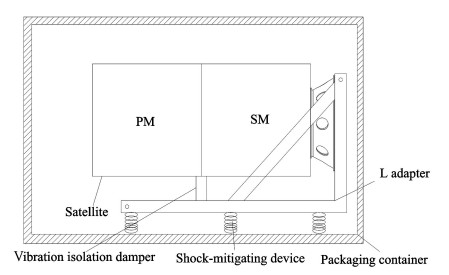
1 Condition of Horizontal Satellite TransportationSatellite transportation using packaging container consists of two parts: road transportation between different satellite buildings, and railway transportation from assembly plant to launching center. Generally, a remote sensing satellite comprises service module (SM) and payload module (PM). The structure diagram of horizontal satellite transportation is shown in Fig. 1. Compared with vertical transportation of separated modules, packaging container should establish L adapter and auxiliary support device. L adapter is installed on shock-mitigating device[14-15]. Satellite is placed on the L adapter through bolt connection, and the vibration isolation damper is installed between the payload module and L adapter.
|
Fig.1 Structure diagram of horizontal satellite transportation |
2 Design of Vibration Isolation Damper 2.1 Structure of Vibration Isolation Damper
According to the requirements of remote sensing satellite packaging containers, especially for satellite horizontal transportation, a vibration isolation damper should be established on the L adapter instead of on the packaging box in order to obtain the same excitation from the transportation vehicle.
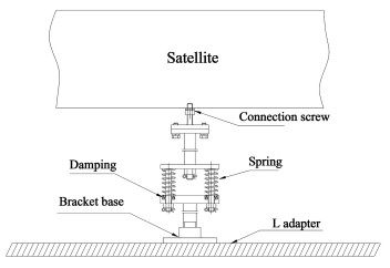
The vibration isolation damper needs sufficient structural strength and flexibility to ensure the safety of satellite transportation, and its installation position should be convenient for installation and adjustment. A vibration isolation damper was designed, which was supplied shock absorption function in the process of horizontal transportation of satellite. The design of vibration isolation damper is shown in Fig. 2. On the top of vibration isolation damper, connection screw was fixed with the auxiliary support joints on satellite[16]. At the bottom of vibration isolation damper, the bracket base was installed on L adapter. The springs, i.e., shock-mitigating device, were set by both sides according to the direction of transportation.
|
Fig.2 Structure diagram of vibration isolation damper |
2.2 Theoretical Model of Vibration Isolation Damper
Vibration is transmitted to the spacecraft through the bottom end of the L adapter and a vibration isolation damper. This state can be regarded as an elastically connected viscous damping system. Theoretical model of vibration isolation damper uses Zener modal[17], which is shown in Fig. 3(a).The system motion equation can be stated as follows:
| $ m \ddot{x}+c\left(\dot{x}-\dot{x}_{1}\right)+k_{2}(x-y)=0 $ | (1) |
| $ k\left(x_{1}-y\right)=c\left(\dot{x}-\dot{x}_{1}\right) $ | (2) |

|
Fig.3 Model of the system |
where m is mass, c is damping, k1 is tandem stiffness, and k2 is main stiffness.
Laplace transforms the two ends of the equation, and the initial derivative is 0.
| $ \left\{\begin{array}{l} m s^{2} X(s)-k_{2} X_{1}(s)+k_{2} X(s)+c s X(s)- \\ \ \ \ \ \ \ \ \ \ \ c s Y s(s)=0 \\ c s X(s)-c s Y(s)=k_{1} Y(s)-k_{1} X_{1}(s) \end{array}\right. $ | (3) |
Based on the above analysis, the differential equation of motion can be obtained as follows:
| $ \begin{gathered} {\left[\left(m s^{2}+k_{2}+c s\right)\left(c s+k_{1}\right)-c^{2} s^{2}\right] X(s)-} \\ {\left[k_{2}\left(c s+k_{1}\right)+c s k_{1}\right] Y(s)=0} \end{gathered} $ | (4) |
The system transfer function can be obtained as follows:
| $ G(s)=\frac{x}{y}=\frac{k_{1}\left(c s+k_{2}\right)+c s k_{2}}{\left(m s^{2}+k_{1}+c s\right)\left(c s+k_{2}^{2}\right)-c^{2} s^{2}} $ | (5) |
Basic incentives are used as system inputs. The frequency response function of the system can be obtained as follows[18]:
| $ \begin{aligned} &T(\lambda, N, \zeta)=\left|\frac{X}{Y}\right|=\\ &\ \ \ \ \sqrt{\frac{1+4[(1+N) / N]^{2} \zeta^{2} \lambda^{2}}{\left(1-\lambda^{2}\right)^{2}+\left(4 / N^{2}\right) \zeta^{2} \lambda^{2}\left(N+1-\lambda^{2}\right)^{2}}} \end{aligned} $ | (6) |
where λ is frequency ratio, ζ is damping ratio, N is the stiffness ratio, and k1=Nk2.
For the above Eq.(6), N is a constant, ζ and λ are variables. An optimal value of the system frequency response function can be found as follows[19]:
| $ \begin{aligned} T_{\text {min }}=& \sqrt{\frac{2+N}{\left(1-\frac{2(N+1)}{N+2}\right)^{2}+\frac{1}{N+1}\left(N+1-\frac{2(N+1)}{N+2}\right)^{2}}}=\\ & \frac{N+2}{N} \end{aligned} $ | (7) |
| $ \lambda=\frac{\omega}{\omega_{0}}=\omega / \sqrt{\frac{k_{2}}{m}}=\sqrt{\frac{2(N+1)}{N+2}} $ | (8) |
| $ \omega=\sqrt{\frac{k_{2}}{m} \frac{2(N+1)}{N+2}} $ | (9) |
| $ \zeta=\frac{c}{2 \sqrt{m k_{2}}}=\frac{N \sqrt{2(N+2)}}{4(N+1)} $ | (10) |
| $ c=\frac{N \sqrt{2 m k_{2}(N+2)}}{2(N+1)} $ | (11) |
Through simplifying the Eqs. (10) and (11), expression of resonance frequency of vibration isolation damper system under optimal damping can be obtained as follows:
| $ \begin{gathered} \omega c=\sqrt{\frac{k_{2}}{m} \frac{2(N+1)}{N+2}} \frac{N \sqrt{2 m k_{2}(N+2)}}{2(N+1)}= \\ k_{2} \frac{N}{\sqrt{N+1}}=\frac{k_{1} \sqrt{k_{2}}}{\sqrt{k_{1}+k_{2}}}=k_{1} \sqrt{\frac{k_{2}}{k_{1}+k_{2}}} \end{gathered} $ | (12) |
| $ \omega=\frac{k_{1}}{c} \sqrt{\frac{k_{2}}{k_{1}+k_{2}}} $ | (13) |
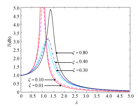
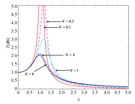
In order to describe vibration isolation damper system model, a numerical simulation was performed. During the simulation process, the mass and main stiffness remained unchanged, and the system transfer rate curves were drawn under different conditions (Fig. 4 and Fig. 5).
|
Fig.4 System transfer rate and damping ratio curves |
|
Fig.5 System transfer rate and stiffness ratio curves |
As the damping ratio increased, the resonance frequency moved from the first resonance frequency to the second resonance frequency. The peak value decreased first, then it reached a minimum value, before finally increasing with the increase of the damp. This behavior shows that there was an optimal damping coefficient in the system. When the system's stiffness ratio was selected, the system's optimal damping system was also determined.
Through analysis of the structure of the vibration isolation damper, it is known that there are two resonance frequencies (Fig. 1). If the damp of system is 0, the first natural frequency of this system is
| $ f_{1}=\frac{1}{2 {\rm{ \mathsf{ π} }}} \sqrt{\frac{k_{2}}{m}} $ | (14) |
If the damp of system is infinite, the system can be regarded as k1 and k2 in parallel. The second natural frequency of this system is
| $ f_{2}=\frac{1}{2 {\rm{ \mathsf{ π} }}} \sqrt{\frac{k_{2}+k_{1}}{m}} $ | (15) |
Through Eq. (7), the minimum stiffness ratio N can be obtained. The high frequency characteristics of the vibration isolation damper depend on the second natural frequency f2. Through Eq. (15), it is known that the value of f2 is determined by the sum of k1 and k2. The smaller the sum of stiffness, the better the high frequency vibration isolation effect. So the best value range of N is between 1 and 2.
To illustrate the impact of the vibration isolation damper on vibration systems, a theoretical model was established as shown in Fig. 3(b). Vibration was transmitted to the spacecraft through the bottom end of the L adapter only. Based on differential equations of motion, mẍ +k2 x-y =0, the system transfer function of the system model without vibration isolation damper can be obtained as follows:
| $ G(\mathrm{j} w)=\frac{X}{Y}=\frac{k_{2}}{k_{2}-m \omega^{2}} $ | (16) |
In addition, the frequency response function of the system model without vibration isolation damper can be obtained as follows:
| $ T(\lambda)=\left|\frac{X}{Y}\right|=\frac{1}{1-\lambda^{2}} $ | (17) |
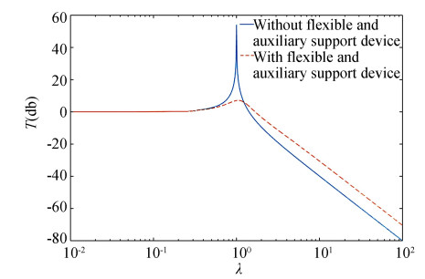
In order to compare the differences between the two models, the system transfer rate curves of two models were drawn under some conditions (Fig. 6), where ζ=0.03, N=1.5.
|
Fig.6 Comparison of the transfer rate curves of the two models |
It can be seen that by adding vibration isolation damper under the payload module (PM), the vibration amplitude of the satellite is greatly suppressed.
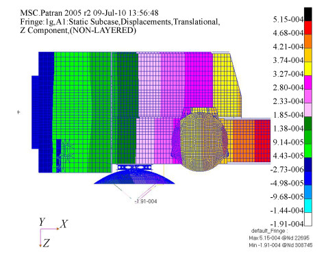
2.3 Static AnalysisIn this paper, the remote sensing satellite was taken as the research object. Its entire mass was 1200 kg. During transportation, the mass of the L adapter was 2400 kg. According to the quality distribution of the satellite, the deformation was calculated under the static load from its own gravity in the process of horizontal position[20]. The analysis result is shown in Fig. 7. The structural finite element model was built, and the fixed position was set at the bottom of the satellite. The analysis result shows that the value of deformation on the top of satellite (PM) was 0.4 mm, and the value of deformation on the vibration isolation damper joint was less than 0.2 mm.
|
Fig.7 Satellite static deformation |
2.4 Dynamic Analysis
According to the theoretical transportation response, the deformation was calculated under the dynamic load from packaging container and L adapter in the process of horizontal transportation of satellite[21]. The structural finite element model was built, and 1 g sinusoidal excitation was set at the bottom of L adapter. The value of critical damping was set at 0.03 by experience.
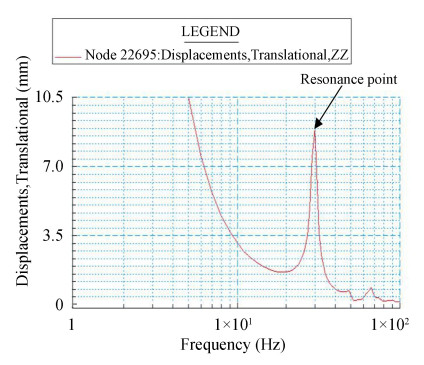
The analysis result is shown in Fig. 8 and Fig. 9, which show that the value of displacement on vibration isolation damper was 8 mm under 1 g sinusoidal excitation. According to the experience of past transportation test, the value of vibration acceleration transferring to L adapter is less than 0.2 g normally, and less than 0.6 g in particular under atrocious transportation condition, e.g., an emergent brake. So it can be concluded that the value of deformation on the vibration isolation damper is less than 5 mm based on linear approximation[22].

|
Fig.8 Deformation of satellite under 1 g sinusoidal excitation |
|
Fig.9 Displacement curve of the vibration isolation damper (1 g) |
2.5 Design of Vibration Isolation Damper
In order to ensure the supporting effect, the vibration isolation damper should bear certain prestressing force under static load condition. So the vibration isolation damper should have height adjustment function before the satellite is lifted into the packaging container. At the same time, the value of prestressing force should not be too robust in order to avoid hurting the structure of satellite.
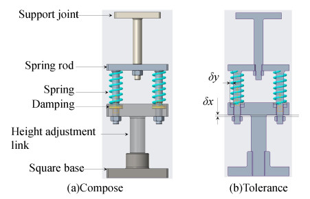
To meet the requirement of satellite structure, the value of prestressing force was about 500 N, and the reaction force on each support joints should be less than 1500 N in the whole process of horizontal transportation of satellite. The damping ratio of the vibration isolation damper was designed as the optimal damping ratio calculated in Section 2.2. The initial length of damping spring should be set according to the installation space, and the coefficient of elasticity about damping spring should be set by maximum reaction force and the acceptable displacement on the vibration isolation damper. Finally, the coefficient of elasticity about damping spring was set 100 N/mm, so the maximum reaction force during the transportation was about 1000 N. According to the satellite structure interface, vibration isolation damper could be designed and divided into 5 parts, which were support joint, spring rod, spring, height adjustment link, and square base. The configuration layout is shown in Fig. 10.
|
Fig.10 Design drawing of vibration isolation damper |
3 Transportation Verification
In order to verify the effect of vibration isolation damper, a technical transportation test was implemented by rail & road. Taking into account the structural characteristics of the remote sensing satellite, the structural strength at the connection position between the PM and SM is large and free of obstacles, which satisfies the installation requirements of the vibration isolation damper. The installation of a vibration isolation damper is shown in Fig. 11(a). In the process of transportation test, laser displacement sensor was installed near the vibration isolation damper to measure the value of displacement of vibration isolation damper joints on satellite. The installation position of laser displacement sensor is shown in Fig. 11(b).

|
Fig.11 The installation of vibration isolation damper and laser displacement sensor |
According to the results of transportation test, the shock acceleration of vibration isolation damper on satellite is bigger by rail than by road. Time domain and frequency domain diagram of Y-direction by rail without vibration isolation damper is shown in Fig. 12 and Fig. 13. Time domain and frequency domain diagram of Y-direction acceleration by rail with vibration isolation damper is shown in Fig. 14 and Fig. 15. Time domain and frequency domain diagram of Y-direction by road without vibration isolation damper is shown in Fig. 16 and Fig. 17. Time domain and frequency domain diagram of Y-direction acceleration by road without vibration isolation damper is shown in Fig. 18 and Fig. 19. It is shown that the maximum value of shock acceleration on vibration isolation damper joints was less than 0.06 g throughout the whole rail transportation test. It is shown that the maximum value of shock acceleration on vibration isolation damper joints was less than 0.02 g throughout the whole road transportation test. So the maximum reaction force on support joints was about 600 N, and the vibration isolation damper met the requirement of horizontal transportation of satellite.

|
Fig.12 Time domain diagram of vibration acceleration by rail (without vibration isolation damper) |

|
Fig.13 Frequency domain diagram of vibration acceleration by rail (without vibration isolation damper) |

|
Fig.14 Time domain diagram of vibration acceleration by rail (with vibration isolation damper) |

|
Fig.15 Frequency domain diagram of vibration acceleration by rail (with vibration isolation damper) |

|
Fig.16 Time domain diagram of vibration acceleration by road (without vibration isolation damper) |

|
Fig.17 Frequency domain diagram of vibration acceleration by road (without vibration isolation damper) |

|
Fig.18 Time domain diagram of vibration acceleration by road (with vibration isolation damper) |

|
Fig.19 Frequency domain diagram of vibration acceleration by road (with vibration isolation damper) |
4 Discussion
Based on static and dynamic analysis, the vibration isolation damper for horizontal transportation of remote sensing satellite was designed and developed. With an example of a remote sensing satellite, the technical parameters were calculated to illustrate how to design the engineering prototype. Experimental results of transportation test using satellite structural model and engineering prototype demonstrate that the vibration isolation damper can meet the requirements of vibration and shock from various transportation conditions.
During satellite transport, it is subject to vibrations from different directions and lateral swing due to vehicle turning should also be considered. In addition, there are differences in the vibration transmitted to the satellite by the different transportation methods of road, railway, and aviation. The vibration isolation damper should include adjustment modules to adapt to different modes of transportation.
| [1] |
Zhang Li, Qi X J, Fu G Q. Vibration response analysis of satellite transportation. Spacecraft Environment Engineering, 2009, 26(Z1): 55-61. (  0) 0) |
| [2] |
Shi L X, Luo K, Dou R C, et al. Dynamics environment excitations during spacecraft transportations. Spacecraft Environment Engineering, 2013, 30(3): 250-255. (in Chinese) DOI:10.3969/issn.1673-1379.2013.03.006.(inChinese) (  0) 0) |
| [3] |
Wu X F, Lei J Y, Li L. Response analysis of liquid rocket engine during road transportation and optimal selection of the support scheme. Structure & Environment Engineering, 2009, 36(6): 8-13. (in Chinese) (  0) 0) |
| [4] |
Wang Q, Yang B, Liu L, et al. The analysis and research of mechanical vibration and dynamic load for horizontal worm screen centrifuge. Proceedings of the 9th International Conference on Vibration Engineering and Technology of Machinery. Nanjing: Chinese Society for Viberation Engineering, 2013: 1-8.
(  0) 0) |
| [5] |
Rittweger A, Muller S, Derund J-F. The new approach for damping modeling in the coupled dynamic load analysis for the Ariane 5 acoustic booster mode load cases. Acta Astronautica, 2012, 81(2): 466-477. DOI:10.1016/j.actaastro.2012.07.017 (  0) 0) |
| [6] |
Neves S G M, Montenegro P A, Azevedo A F M, et al. A direct method for analyzing the vertical vehicle-structure interaction. Engineering Structures, 2014, 69: 83-89. DOI:10.1016/j.engstruct.2014.02.027 (  0) 0) |
| [7] |
Zhang J, Chen Y, Zhang Z Y, et al. Research on the random vibration test of the satellite. Journal of Mechanical Strength, 2006, 28(1): 16-19. (in Chinese) DOI:10.16579/j.issn.1001.9669.2006.01.004.(inChinese) (  0) 0) |
| [8] |
Piszczek K, Niziol J. Random Vibration of Mechanical Systems. Hoboken, New Jersey: Wiley, 1986.
(  0) 0) |
| [9] |
Shorter P, Cotoni V, Langley R. Numerical and experimental validation of hybrid FE-SEA method. INTER-NOISE and NOISE-CON Congress and Conference Proceedings, NoiseCon04. Reston, VA: Institute of Noise Control Engineering, 2004: 380-388.
(  0) 0) |
| [10] |
Stephens V M. A2100 Commercial Satellites Integrated Mechanical Analysis. Lockheed Martin Missiles & Space Sunnyvale, 1997.
(  0) 0) |
| [11] |
Shorter P, Cotoni V, Langley R. Numerical and experimental validation of hybrid FE-SEA method. INTER-NOISE and NOISE-CON Congress and Conference Proceedings, NoiseCon04. Reston, VA: Institute of Noise Control Engineering, 2004.
(  0) 0) |
| [12] |
Delaere K, Iadevaia M, Heylen W, et al. Statistical energy analysis of acoustic noise and vibration for electric motors: transmission from air gap field to motor frame. Conference Record of the 1999 IEEE Industry Applications Conference. Thirty-Forth IAS Annual Meeting. Piscataway: IEEE, 1999, 1897-1902. DOI:10.1109/IAS.1999.805997 (  0) 0) |
| [13] |
Zhang H, Zong Y Y. Vibration environment and reliability analysis of solar array in transportation. Spacecraft Environment Engineering, 2014, 31(5): 536-542. (in Chinese) DOI:10.3969/j.issn.1673-1379.2014.05.015.(inChinese) (  0) 0) |
| [14] |
Wu Q Q, Yue H H, Liu R Q, et al. Parametric design and multiobjective optimization of maglev actuators for active vibration isolation system. Advances in Mechanical Engineering, 2014, 2014: 215358. DOI:10.1155/2014/215358 (  0) 0) |
| [15] |
Liu L, Tan K K, Guo Y, et al. Active vibration isolation based on model reference adaptive control. International Journal of Systems Science, 2014, 45(2): 97-108. DOI:10.1080/00207721.2012.683834 (  0) 0) |
| [16] |
Moshrefi-Torbati M, Forrester J A, Forrester A I J, et al. Novel active and passive anti-vibration mountings. Journal of Sound and Vibration, 2012, 331(7): 1532-1541. DOI:10.1016/j.jsv.2011.12.005 (  0) 0) |
| [17] |
Brennan M J, Carrella A, Water T P, et al. On the dynamic behavior of a mass supported by a parallel combination of a spring and an elastically connected damper. Journal of Sound and Vibration, 2008, 309(3-5): 823-837. DOI:10.1016/j.jsv.2007.07.074 (  0) 0) |
| [18] |
Ding W J. Damping Theory. Beijing: Tsinghua University Press, 1988. (in Chinese)
(  0) 0) |
| [19] |
Wang C X, Sun J Y, Zhang Z Y, et al. Design and experiment of three-parameter isolation system with optimal damping. Journal of Mechanical Engineer, 2015, 51(15): 90-96. (in Chinese) DOI:10.3901/JME.2015.15.090 (  0) 0) |
| [20] |
Hoque E, Mizuno T, Ishino Y, et al. A six-axis hybrid vibration isolation system using active zero-power control supported by passive weight support mechanism. Journal of Sound and Vibration, 2010, 329(17): 3417-3430. DOI:10.1016/j.jsv.2010.03.003 (  0) 0) |
| [21] |
Hauge G S, Campbell M E. Sensors and control of a space-based six-axis vibration isolation system. Journal of Sound and Vibration, 2003, 269(3-5): 913-931. DOI:10.1016/S0022-460X(03)00206-2 (  0) 0) |
| [22] |
Lee D-O, Kang L-H, Han J-H. Active vibration isolation demonstration system using the piezoelectric unimorph with mechanically pre-stressed substrate. Journal of Intelligent Material Systems and Structures, 2011, 23(13): 1399-1409. DOI:10.1177/1045389X11411215 (  0) 0) |
 2021, Vol. 28


