2. School of Aerospace Engineering and Applied Mechanics, Tongji University, Shanghai 200092, China
Ceramic thermal barrier coatings (TBCs) have been applied to metal substrates to make them resistant to thermal shock in the aerospace and electronic devices, due to its many well-known advantageous properties, such as insulation and corrosion resistance. The accurate prediction of heat propagation in these devices may be important in ensuring their efficient work and design. Its heat transfer and thermal stress properties have been analyzed by the Fourier law, which is traditionally used to analyze the behavior of macroscopic heat transport. Recently, as nanotechnology and ultrafast processes continue to develop, TBCs with thicknesses between 10 nm and 100 nm are being used extensively in devices (Zeng and Chen[1]). The average free path of the energy carrier has been reached (microscale effect in size), resulting in the discontinuity of heat conduction because of the insufficient number of collisions of the energy-required heat conduction. In addition to microscale effect in time, the high-speed thermal shock reaches femtosecond or picosecond order[2], which is shortened into the range of the heat carrier mean free time, resulting in the premise of Fourier heat conduction theorem, in which the heat conduction velocity is infinite, thus not established. Therefore, there are obvious differences between the heat conduction theory at the microscopic scale and those at the macroscopic scale. New research indicates that the heat transfer mechanics at the micro-and nano-scales may deviate significantly from those at the macro-scale. For example, by the experiment of short-pulse laser heating on metals, Qiu and Tien[3] have verified that the actual heat flux is not as fast as the Fourier law prediction.
Many scholars have studied and published non-Fourier heat transport models that are based on different physical theories. Maxwell[4] first reported that the heat propagation speed is limited and modified the Fourier law by adding a relaxation time. Landau[5] proved heat waves in liquid helium Ⅱ propagate with a finite speed. The CV model by modifying the Fourier law to interpret the thermal wave phenomenon was recently applied by some researchers (Cattaneo[6] and Vernotte[7]). Guyer and Krumhansl[8] brought forward the phonon scattering model by directly solving the linearized Boltzmann equation for heat transport by phonon collision and scattering. This model was improved later by Joseph and Preziosi[9], who emphasized the interrelation with a Jeffrey's type of heat flux equation. Tzou[10] proposed the dual-phase-lag model with an emphasis on the lagging behavior at the micro-scale. Joshi and Majumdar[11-12]solved the linearized Boltzmann transport equation to derive the EPRT and analyzed heat transfer in dielectric thin films. The EPRT is valid for microscale in both time and size. Qiu et al.[13-14]proposed a two-step model with a quantum mechanical and statistical basis for a short-pulsed laser heating a metal film. Choudhuri[15] established the three-phase delay hyperbolic heat conduction equation (TPL) by joining the phase delay of heat flow, temperature gradient and thermal displacement gradient.
At present, lots of studies researched the objects in the fields of biology and semiconductor. Li[16] compared the analytical and numerical solutions of non-Fourier temperature field of laminated plate and laminated cylinder, and proved that the numerical solution obtained by backward difference separation is absolutely stable. Atfi and Talaee[17-18]studied the non-Fourier thermal response of finite hollow cylinder subjected to periodic thermal shock based on C-V model. Cao[19]researched the dynamic response of piezoelectric pole under thermal shock of heat source based on fractional order theory. Yu[20]solved the temperature field and stress of the laminated material. On this basis, he studied the stress distribution at the crack tip under thermal shock. Li[21] analyzed the fracture behavior of solid plates under thermal shock by the non-Fourier. Zhang and Li[22-23] analyzed transient thermal stress and intensity factors for a circumferential crack in a hollow cylinder by generalized fractional heat conduction. Guo[24]analyzed the fracture mechanics of plate, sandwich plate, coating, cylinder and other structures with the two-phase delayed model. Zhang and Chen[25] studied the temperature field, displacement field and stress intensity factor of cracked hollow cylinder under thermal shock by using single-phase delayed non-Fourier heat conduction mode. Mao et al.[26] studied silicon crystal with point defect scatter by molecular dynamics. Those researches are mainly aimed at only on the TBCs rather than the TBCs structure (thermal barrier coating and substrate), and kingdom is mainly in heat conduction.
In this paper, the equations combining the EPRT (for the TBCs) and the Fourier law (for the substrate) are numerically solved by the temperature field under thermal shock. The thermal stresses in the ceramic TBCs and J-integral of crack at the ceramic TBCs surface are studied by the finite element method, and the results are compared with those obtained by the Fourier law on both the TBCs and the substrate. The influence of the physical heat properties of the TBCs (such as the relaxation time and phonon speed) on the temperature field and the thermal stress as well as J-integral at an edge crack tip is analyzed.
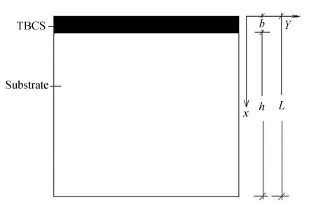
1 Calculated Temperature Field and Stress and J-Integral 1.1 Heat Transportation Theoretical ModelThermal shock in the direction of the x-axis has been studied (Fig. 1).
|
Fig.1 Structure of the nano-scale ceramic TBCs and the substrate |
Because the thickness size of the ceramic TBCs is comparable with the mean free path(MFP) of typical phonons, which are considered to be the major heat carriers in the dielectric material, the phonon intensity for the ceramic TBCs ((0≤x≤b)) is numerically predicted by the EPRT[11]:
| $ \left\{ {\begin{array}{*{20}{l}} {\frac{1}{v}\frac{{\partial I_\omega ^ + }}{{\partial t}} + \mu \frac{{\partial I_\omega ^ + }}{{\partial x}} = }&{}\\ {\frac{{\frac{1}{2}\int_{ - 1}^1 {{I_\omega }} {\rm{d}}\mu - I_\omega ^ + }}{{\tau v}}}&{, \;\;\;{\kern 1pt} \mu > 0}\\ {\frac{1}{v}\frac{{\partial I_\omega ^ - }}{{\partial t}} + \mu \frac{{\partial I_\omega ^ - }}{{\partial x}} = }&{}\\ {\frac{{\frac{1}{2}\int_{ - 1}^1 {{I_\omega }} {\rm{d}}\mu - I_\omega ^ - }}{{\tau v}}, }&{\mu < 0} \end{array}} \right. $ | (1) |
where Iω is the phonon intensity in heat transport, v is the phonon speed, and τ is the phonon relaxation time. Furthermore, μ=cosθ, where θ is the angle between the phonon propagation and the x-axis, ω is the phonon frequency (ωD=κBTD/ ħ, where ωD is the Debye cutoff phonon frequency, κB=1.381×10⁻²³ J/K is Boltzmann's constant, TD= 647 K is the Debye temperature, and ħ =6.626×10⁻³⁴/2π J·s is Plank's constant). One could assume that the phonon intensity is in energy equilibrium under per frequency. The ''-'' and ''+'' superscripts represent the backward and forward transport phonons in the correspondence with the directional cosine.
Once, the phonon intensity is numerically solved by Eqs. (1), the temperature can be calculated by the Bose-Einstein distribution function at an equilibrium state[11]:
| $ \begin{array}{l} I_\omega ^0(T) = \frac{1}{2}\int_{ - 1}^1 {{I_\omega }} {\rm{d}}\mu = \\ \;\;\;\;\;\;\;\;\;\;\;\;\;\sum\limits_p {{v_p}} \frac{{\hbar \omega D(\omega )}}{{\exp \left[ {\frac{{\hbar \omega }}{{{\kappa _B}T(x)}}} \right] - 1}} \end{array} $ | (2) |
where Iω0 is the equilibrium phonon intensity obtained by the equilibrium temperature, D(ω) is the phonon density of states per unit volume (D(ω)=ω2/2π2v3), and p is the index of the phonon polarization direction[11].
Because the thickness of the substrate (b≤x≤b+ h) is much larger than the MFP, the temperature field of the substrate is predicted by the Fourier law[25]:
| $ \frac{{{\partial ^2}T}}{{\partial {x^2}}} = \alpha \frac{{\partial T}}{{\partial t}} $ | (3) |
where α is the thermal diffusivity.
1.2 Initial Conditions and Boundary ConditionsAt t=0, the ceramic TBCs and the substrate are assumed to be at a uniform temperature T0 and remain adiathermal.
At t>0, the temperature at x=0 is instantaneously raised to T1. For EPRT, the intensity function for incoming phonon remains constant, and for Fourier's law, the boundary condition is constant temperature T1. An idealized thermal shock on the surface of the TBCs is assumed, i.e., the heat transfer coefficient is infinitely large. Under this condition, the thermal stress is the greatest.
Because the substrate material is a metal or an alloy, the phonons are absolutely reflected at the bottom of the TBCs.
One assumes that there is no heat loss, and the two materials are in perfect thermal contact at the interface of the ceramic TBCs and substrate, and at the bottom of the substrate the temperature is a constant T0.
The above conditions of the phonon and heat transport are expressed as follows:
| $ \left\{ {\begin{array}{*{20}{l}} {t = 0:I_\omega ^ + (0, x, \mu ) = }&{}\\ {I_\omega ^ - (0, x, \mu ) = I_\omega ^0\left( {{T_0}} \right), }&{0 \le x \le b}\\ {t = 0:T = {T_0}, }&{b \le x \le b + h}\\ {t = 0:\frac{{\partial T}}{{\partial t}} = 0, }&{b \le x \le b + h}\\ {x = 0:I_\omega ^ + (t, 0, \mu ) = I_\omega ^0\left( {{T_1}} \right), }&{t > 0}\\ {x = b:I_\omega ^ - (t, b, \mu ) = I_\omega ^ + (t, b, \mu ), }&{t > 0}\\ {x = b + h:\frac{{\partial T}}{{\partial x}} = 0, }&{t \ge 0} \end{array}} \right. $ | (4) |
Eq. (1) are two wave equations in the integrodifferential form. Eq. (1) are numerically solved by an explicit upstream differencing method, i.e., by backward differencing when the phonon intensity wave is moving in the positive x-direction (the first equation in Eq.(1)) and by forward differencing when it is moving in the negative x-direction (the second equation in Eq. (1)). To guarantee the stability of the numerical computation, the forward difference in time is applied while ensuring that Δt≤Δx/v μ in Eq. (1) and Eq. (3). The range of the cosine of the angle μ(-1≤μ≤1) is divided into K divisions. The integral in Eq. (1) can be approximated by a Gaussian quadrature[12]as
| $ \int_{ - 1}^1 I (\mu ){\rm{d}}\mu = \sum\limits_{i = 1}^k {{w_i}} I\left( {{\mu _i}} \right) $ | (5) |
where μi shows discrete directions and wi is the weighting factor. The integrodifferential equations can be converted into the differential equation of the unknown Ii. In Eq. (3), a complete implicit difference method is used to calculate temperature field. Eq. (1) and Eq. (3) can be represented in the finite difference expressions as follows:
| $ \left\{ {\begin{array}{*{20}{l}} {I_{j, \omega i}^{n + 1, + } = \left( {1 - {\mu _i}A - B} \right)I_{j, \omega i}^{n, + } + {\mu _i}AI_{j - 1, \omega i}^{n, + } + }&{}\\ {(B/2)\sum\limits_{i = 1}^k {{w_i}} I_{j, \omega i}^n, }&{\mu > 0, 0 \le x \le b}\\ {I_{j, \omega i}^{n + 1, - } = \left( {1 + {\mu _i}A - B} \right)I_{j, \omega i}^{n, - } - {\mu _i}AI_{j + 1, \omega i}^{n, - } + }&{}\\ {(B/2)\sum\limits_{i = 1}^k {{w_i}} I_{j, \omega i}^n, }&{\mu < 0, 0 \le x \le b}\\ { - \alpha \lambda T_{j - 1}^{n + 1} + (1 + 2\alpha \lambda )T_j^{n + 1} - }&{}\\ {\alpha \lambda T_{j + 1}^{n + 1} = T_j^n, }&{b \le x \le b + h}\\ {I_{j, \omega i}^{0, + } = I_{j, \omega i}^{0, - } = I_\omega ^0\left( {{T_0}} \right), }&{0 \le x \le b}\\ {T_j^0 = {T_0}, }&{b \le x \le b + h}\\ {T_j^{ - 1} = T_j^0, }&{b \le x \le b + h}\\ {I_{0, \omega i}^{n, + } = I_\omega ^0\left( {{T_1}} \right), }&{t > 0}\\ {I_{D, \omega i}^{n, - } = I_{D, \omega i}^{n, + }, }&{t > 0}\\ {T_{L + 1}^n = T_{L - 1}^n, }&{t \ge 0} \end{array}} \right. $ | (6) |
where the superscript n represents nth time step, subscript i is the index of the unit direction vector, subscript j represents the jth node, A=vΔt/Δx, B=Δt/τ, D is the last node of TBCs, and L is the last node of the substrate. Material parameters[27] in the TBCs and substrate are shown in Table 1.
| Table 1 Parameters and material properties relevant to heat transport |
1.4 Thermal Stress and Fracture Calculation by Finite Element
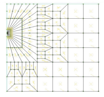
In this work, the thermal stress and J-integral at the crack tip in the TBCs are analyzed using the finite element method after numerical calculation of the temperature field. The numerical calculations make use of the element software MSC.MARC, which can be applied in the thermal stress and J-integral[28]. The stress and temperature analyses are uncoupled. The TBCs and the substrate are modeled by a four-node plane strain and quadratic elements in the stress analysis, because the model is a good elastic body without plastic deformation. In fracture mechanics analysis, it is assumed that the fracture is an edge crack that opens to the surface and its length is 2×10⁻⁸ m. Quarter point 8-node isoparametric degenerate singular elements are employed in modeling the region near the crack tip, as shown in Fig. 2.
|
Fig.2 Crack at the ceramic TBCs |
The assumed boundary conditions put constraints on the displacement field in the y-axis. The displacements only take place along the x-axis, but at the bottom of substrate, the x-displacement is assumed to be zero. The initial temperature should be T0 at all nodes. The thermal loads are derived from temperature fields. The parameters and the material properties used in the heat transport, thermal stress, and J-integral numerical calculations are listed in Tables 1 and 2[29-32]. The parameters and properties remain constant unless otherwise specified in the numerical calculations and subsequent analysis.
| Table 2 Material properties relevant to the analysis |
2 Results and Discussion 2.1 Temperature Distribution and Comparison
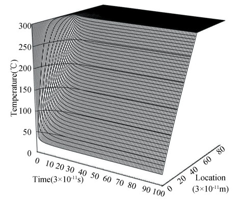
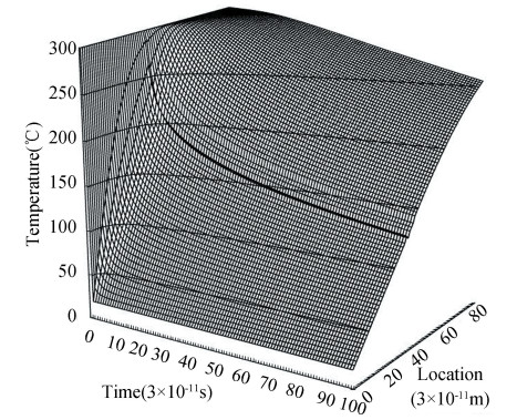
Figs. 3 and 4 show temperature field from EPRT and the Fourier law, respectively. It is clear that the temperature jumps on the TBCs surface are calculated by the EPRT, which are not shown by the Fourier law. In the TBCs and substrate, the amplitude of temperature attenuation obtained from the EPRT is lower than the attenuation from the Fourier law. Because the heat transfer velocity is finite according to the EPRT, where the heat transport velocity is represented by income and out-coming of phonon, it is infinite for the Fourier law.
|
Fig.3 Temperature field obtained from EPRT |
|
Fig.4 Temperature field obtained from Fourier heat conduction model |
2.2 Results of Thermal Stress and J-integral
The comparison between the thermal stress in the y-direction obtained from the EPRT and that obtained from the Fourier law is presented in Fig. 5. Both of the thermal stress profiles along the x-direction are similar, i.e., the thermal stresses gradually change from tensile stress to compressive stress along the x-direction in the TBCs and are only compressive stresses along the x-direction within the substrate. But the thermal stress, special tensile stress in the TBCs calculated with the EPRT, is lower than that calculated from the Fourier law, because temperature contrast from the surface of the TBCs to the bottom of the substrate, which is obtained from the EPRT, is lower than that obtained from the Fourier law. At the interface, a thermal stress discontinuity occurs for the difference in the characters between the two materials.

|
Fig.5 Comparison of the thermal stress in the y-axis obtained from the EPRT with that obtained from the Fourier law along the x-axis |
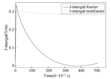
For reasons given above, the amplitude of temperature attenuation from the EPRT is lower than the attenuation from the Fourier law, and the J-integral from the EPRT is lower than the results from the Fourier law in the TBCs and changes slowlier with time, and J-integral from the Fourier law decreases with time in Fig. 6, because temperature difference between the top of TCBs and bottom of substrate from EPRT changes slowlier with time than that from the Fourier law.
|
Fig.6 Comparison of the J-integral obtained from the EPRT with that obtained from the Fourier |
3 Influence of the TBCs Heat Physical Properties on Temperature, Thermal Stress and J-Integral 3.1 Influence of Phonon Speed
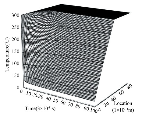
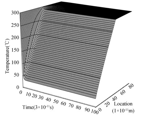
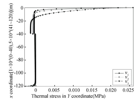
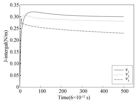
The temperature field, thermal stress profiles and J-Integral at the crack tip predicted by the EPRT with different phonon speeds (v1=8×10² m/s, v2=1.3804×10³ m/s, v3=5×10³ m/s) are shown in Figs. 3, 7, 8, 9 and 10.
|
Fig.7 Change of temperature fields with the phonon speed v1 |
|
Fig.8 Change of temperature fields with the phonon speed v3 |
|
Fig.9 Thermal stress profiles predicted by the EPRT for different phonon speeds |
|
Fig.10 J-integral predicted by the EPRT for different phonon speeds |
At the surface of the TBCs, the amplitude of temperature attenuation decreases with increasing phonon speed. However, in the TBCs, the amplitude of temperature attenuation increases with increasing phonon speed, because the intensity function of incoming phonon remains constant at the surface of the TBCs for the EPRT, and the intensity of out-coming phonon increases with increasing phonon speed, so the temperature jump increases, whereas in the TBCs, the phonon transport increases with increasing phonon speed, so the heat transport increases.
At the surface of the TBCs, the magnitude of the thermal stress decreases as the phonon speed increases. But in the TBCs, the thermal stress rises with the rise of phonon speed. The J-integral at the crack tip decreases with increasing phonon speed.
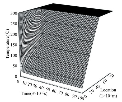
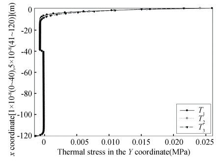
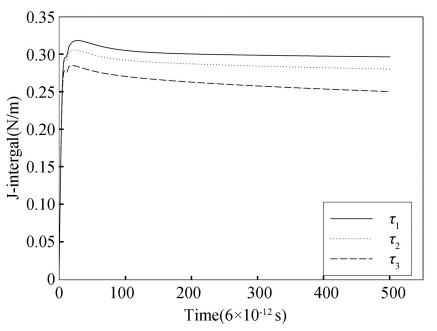
3.2 Influence of Relaxation TimeThe temperature field, thermal stress profile and J-Integral at the crack tip predicted by the EPRT with different relaxation times (τ1=3×10-12 s, τ2=6×10-12 s, τ3=1.2×10⁻¹¹ s) are shown in Figs. 3, 11, 12, 13 and 14.
|
Fig.11 Change of temperature fields with relaxation time τ1 |

|
Fig.12 Chang of temperature fields with relaxation time τ3 |
|
Fig.13 Thermal stress profiles predicted by the EPRT for different relaxation times |
|
Fig.14 J-integral predicted by the EPRT for different relaxation times |
At the surface of the TBCs, the amplitude of temperature attenuation descends with the increase of relaxation time. But the amplitude of temperature attenuation increases with increasing relaxation time in the TBCs.
On the surface of the TBCs, the thermal stress decreases with the increase of relaxation time. Nevertheless, in the TBCs, the thermal stress and compressive stress increase for the same reason as stated above. The J-integral at the crack tip decreases with increasing relaxation time.
4 ConclusionsThis study numerically analyzed temperature field, thermal stress and J-integral obtained from the EPRT and from the Fourier law. The following conclusions can be drawn:
1) For nano-ceramic TBCs under thermal shock, the temperature field, thermal stress and J-integral derived from the EPRT are lower than those derived from the Fourier law.
2) The temperature attenuation and thermal stress decrease on the surface of the TBCs with increasing phonon speed and relaxation time, but the amplitude of temperature attenuation and thermal stress in the TBCs increase with increasing phonon speed and relaxation time.
3) J-integral at the crack tip decreases with increasing phonon speed and relaxation time.
| [1] |
Zeng T, Chen G. Phonon heat conduction in thin films: impacts of thermal boundary resistance and internal heat generation. Journal of Heat Transfer, 2001, 123(3): 340-347. DOI:10.1115/1.1351169 (  0) 0) |
| [2] |
Ding Y, Ding Y, Cao T T, et al. Numerical simulation and experimental analysis on femtosecond ablation of K24 superalloy. Journal of Harbin Institute of Technology, 2017, 49(7): 131-138. (in Chinese) DOI:10.11918/j.issn.0367-6234.201705023 (  0) 0) |
| [3] |
Qiu T Q, Tien C L. Short-pulse laser heating on metals. International Journal of Heat and Mass Transfer, 1992, 35(3): 719-726. DOI:10.1016/0017-9310(92)90131-B (  0) 0) |
| [4] |
Maxwell J C. On the dynamic theory of gases. Philosophical Transactions of the Royal Society of London, 1867, 157: 49-88. DOI:10.1098/rstl.1867.0004 (  0) 0) |
| [5] |
Landau L. The theory of superfluidity of heliumⅡ. Physical Review, 1941, 60(4): 356-358. DOI:10.1103/PhysRev.60.356 (  0) 0) |
| [6] |
Cattaneo C. A form of heat conduction equation which eliminates the paradox of instantaneous propagation. Compue Rendus, 1958, 247(4): 431-433. (  0) 0) |
| [7] |
Vernotte P. Paradoxes in the continuous theory of the heat equation. Comptes Rendus de l'Académie des Sciences, 1958, 246(3): 3154-3155. (  0) 0) |
| [8] |
Guyer R A, Krumhansl J A. Solution of the linearized phonon Boltzmann equation. Physical Review, 1966, 148(2): 766-778. DOI:10.1103/PhysRev.148.766 (  0) 0) |
| [9] |
Joseph D D, Preziosi L. Heat waves. Review of Modern Physics, 1989, 61(1): 41-73. DOI:10.1103/RevModPhys.61.41 (  0) 0) |
| [10] |
Tzou D Y. The generalized lagging response in small-scale and high-rate heating. International Journal of Heat and Mass Transfer, 1995, 38(17): 3231-3240. DOI:10.1016/0017-9310(95)00052-B (  0) 0) |
| [11] |
Joshi A A, Majumdar A. Transient ballistic and diffusive phonon heat transport in the films. Journal of Applied Physics, 1993, 74(1): 31-39. DOI:10.1063/1.354111 (  0) 0) |
| [12] |
Majumdar A. Microscale heat conduction in dielectric thin films. Journal of Heat Transfer, 1993, 115(1): 7-16. DOI:10.1115/1.2910673 (  0) 0) |
| [13] |
Qiu T Q, Juhasz T, Suarez C, et al. Femtosecond laser heating of multi-layer metals-Ⅱ. experiments. International Journal of Heat and Mass Transfer, 1994, 37(17): 2799-2808. DOI:10.1016/0017-9310(94)90397-2 (  0) 0) |
| [14] |
Qiu T Q, Tien C L. Femtosecond laser heating of multi-layer metal-I. analysis. International Journal of Heat and Mass Transfer, 1994, 37(17): 2789-2797. DOI:10.1016/0017-9310(94)90396-4 (  0) 0) |
| [15] |
Choudhuri S K R. On a thermoelastic three-phase-lag model. Journal of Thermal Stresses, 2007, 30(3): 231-238. DOI:10.1080/01495730601130919 (  0) 0) |
| [16] |
Li J E. Numerical of Non-Fourier Heat Conduction and Thermal Stress. Harbin: Harbin Institute of Technology, 2010. (in Chinese)
(  0) 0) |
| [17] |
Atfi G, Talaee M R. Non-fourier temperature field in a solid homogeneous finite hollow cylinder. Archive of Applied Mechanics, 2011, 81: 569-583. DOI:10.1007/s00419-010-0436-5 (  0) 0) |
| [18] |
Talaee M R, Atfi G. Non-Fourier heat conduction in a finite hollow cylinder with periodic surface he at flux. Archive of Applied Mechanics, 2011, 1(12): 1793-1806. DOI:10.1007/s00419-011-0518-z (  0) 0) |
| [19] |
Cao L C. Dynamic Response of a Thermopiezoelectric Rod with Fractional Order Strain Thermoelastic Theory. Lanzhou: Lanzhou University of Technology, 2020. (in Chinese)
(  0) 0) |
| [20] |
Yu J. Non-Fourier Heat Conduction and Thermal Shock Fracture Research of Layered Materials. Harbin: Harbin Institute of Technology, 2013. (in Chinese)
(  0) 0) |
| [21] |
Li J E. Study of Thermal Conductivity of Core Materials and Thermal Shock Fracture Behavior of Face Materials for the Foam Sandwich Structures. Harbin: Harbin Institute of Technology, 2014. (in Chinese)
(  0) 0) |
| [22] |
Zhang X Y, Li X F. Transient thermal stress intensity factors for a circumferential crack in a hollow cylinder based on generalized fractional heat conduction. International Journal of Thermal Sciences, 2017, 121(7): 336-347. DOI:10.1016/j.ijthermalsci.2017.07.015 (  0) 0) |
| [23] |
Zhang X Y, Li X F. Thermal shock fracture of a cracked thermoelastic plate based on time-fractional heat conduction. Engineering Fracture Mechanics, 2017, 171(11): 22-34. DOI:10.1016/j.engfracmech.2016.11.033 (  0) 0) |
| [24] |
Guo S L. Thermal Shock Fracture Mechanics Analysis Based Non-Fourier Heat Conduction Theory. Harbin: Harbin Institute of Technology, 2018. (in Chinese)
(  0) 0) |
| [25] |
Zhang Y B, Chen A J. Numerical analysis for non-fourier thermodynamic response of a thick-walled hollow cylinder with cracks under thermal shock. Journal of Vibration and Shock, 2020, 39(4): 278-283. (in Chinese) (  0) 0) |
| [26] |
Mao Y C, Xiong Y H, Yue Y N. Thermal conductivity of silicon crystal and effects of point defect scatterby molecular dynamics. Journal of Harbin Institute of Technology, 2019, 51(7): 112-120. (in Chinese) DOI:10.11918/j.issn.0367-6234.201902084 (  0) 0) |
| [27] |
Tzou D Y. Macro-to Microscale Heat Transfer the Lagging Behavior, Second Edition. Hoboken, New Jersey: John Wiley & Sons, 2015.
(  0) 0) |
| [28] |
Feng C, Sun D D, Chen H H. New Marc Instance Tutorials and Questions Analysis. Beijing: China Water & Power Press, 2012. (in Chinese)
(  0) 0) |
| [29] |
Boley B A, Weiner J H. Theory of Thermal Stresses. New York: John Wiley and Sons Inc., 1960.
(  0) 0) |
| [30] |
Yan Z D, Wang H L. 1993. Thermal Stress. Beijing: Higher Education Press, 1991. (in Chinese)
(  0) 0) |
| [31] |
Luikov A V. Analytical Heat Diffusion Theory. New Yock: Academic Press, 1968.
(  0) 0) |
| [32] |
Wu G, Yao L J, Peng R Q, et al. Aluminum and Aluminum Alloy Manual Book. Beijing: Science Press, 1994. (in Chinese)
(  0) 0) |
 2021, Vol. 28


