2. Department of Mechanical Engineering, Faculty of Engineering and Advanced Manufacturing & Material Processing (AMMP Centre), University of Malaya, Kuala Lumpur 50603, Malaysia;
3. Department of Mechanical Engineering, Nagaoka University of Technology, Nagaoka 940-2188, Japan;
4. Department of Metallurgical Engineering, Tokai University, Hiratsuka 259-1292, Japan;
5. Department of Mechanical Engineering, Faculty of Engineering and Centre of Advanced Materials (CAM), University of Malaya, Kuala Lumpur 50603, Malaysia
Porous metal has been widely employed in thermal applications such as heat exchanger[1-2], heat sink[3], engine combustion in electronics, aircraft, and automotive systems[4]. Porous metal is an integral part of cooling systems due to its high surface area where heat can be transferred efficiently within a small volume of porous metal[5].
Previous research on porous metal heat exchanger examined the consequences of different materials and their pore densities[6-7]. The main focus of these research was the performance of the heat exchangers in terms of their heat transfer ability, pressure drop efficiency, optimization, and modeling[8]. However, there is a considerable gap in the study of brazed joint morphology and mechanical properties between metal and porous metal. Usually, the design of a heat exchanger is optimized for its performance and cost without considering the joining properties of the heat exchanger. Lunsford[9] presented a guideline on the design processing of brazed aluminium (Al) heat exchanger. The author also stated that the technology of brazed heat exchanger had not been fully capitalized. In addition, the performance of a heat exchanger can be influenced by its joining properties. Boomsma et al.[10] reported that flawed brazing might impinge the heat transfer behavior due to the flow resistance near the wall.
The primary purpose of metal/porous metal joining is to study the morphology and mechanical properties of the brazed joint. Normally, porous metal is sandwiched between solid metals that act as a substrate. This sandwich arrangement provides a sturdy structure. Current study has selected Cu as a material for substrate (top and base) and porous metal while amorphous Cu-based was chosen as a filler metal. Cu is generally known for its high-temperature resistance and as an excellent conductor of heat and electricity.Porous Cu regains a favor back to be utilized in the heat exchanger due to its lightweight. Apart from that, inadequate research on brazed Cu compared with brazed Al has increased the urgency of the study of the former[11]. On the other hand, amorphous filler metal can be produced by rapid solidification through roller machine to yield foil filler metal[12]. The flexibility of foil allows the brazed cross-section to be filled easily without leaving behind a significant brazed gap. Amorphous Cu-9.0Sn-7.0Ni-6.0P is an excellent candidate to braze Cu/porous Cu due to its high chemical homogeneity, good wettability, free flux, and better flexibility[13]. The inclusion of Sn in the filler metal reduces its melting point. Both Ni and P can enhance its corrosion resistance while play a role as dissolvent[12]. This paper investigated the failure of Cu and porous Cu brazed joint from the perspective of shear fracture and joining interface.
1 Experiment SetupPorous Cu with pore densities of 15 pores per inch (PPI), 25 PPI, and 50 PPI were supplied by the manufacturer of Duranice Applied Materials (Dalian, China). The microscopic images of the porous Cu were characterised using a digital microscope (Keyence, Osaka, Japan). Cu was purchased from C & W Hardware (Kuala Lumpur, Malaysia). Amorphous Cu-9.0Sn-7.0Ni-6.0P (VZ 2250) was obtained from Vacuumschmelze GMBH & Co. Kg. (Hanau, Germany) to join Cu and porous Cu. The joining was performed in a brazing furnace in an atmosphere of argon (Ar2) gas. Cu was ground with silicon carbide (SiC) abrasive papers (Pace Technologies, Arizona, USA) before being brazed in the laboratory furnace VMK-Vacuum instrument (Linn High Therm, Eschenfelden, Germany). The specimen was arranged in a sandwich configuration as shown in Fig. 1(a). Brazing was performed at temperatures of 660 ℃, 680 ℃, 700 ℃, and 720 ℃ according to the manufacturer's suggestion and references from previous studies with a holding time of 5 min and a heating rate of 5 ℃/min[11, 14]. The brazed Cu/VZ 2250/porous Cu/VZ 2250/Cu with different Cu pore densities were ground with 600, 800, and 1200 grade SiC abrasive papers to obtain a cross-section of the brazed joint. The specimens were polished with 3 μm and 1 μm diamond suspensions (Buehler, Illinois, United States) followed by etching with copper etchant solution (Reveal Technologies Enterprise, Selangor, Malaysia). The etchant solution contained 3% hydrogen peroxide and 30% ammonia.

|
Fig.1 Experiment on Cu/porous Cu/Cu specimens |
The shear test was performed in room temperature with Instron Universal Testing Machine 3369 with the maximum capacity of the load cell of 50 kN equipped with Bluehill 2.0 software (Instron Inc., Norwood, USA) as shown in Fig. 1(b). The test was carried out under displacement control mode at a cross-head speed of 1 mm/min. Vickers Microhardness test was conducted using DUH-211s Shimadzu Dynamic Ultra Microhardness Tester (Shimadzu Corp., Tokyo, Japan). The microhardness measurements were made with an indentation load of 100 mN at the rate of 10 mN/s for 5 s. Each specimen was tested with three different samples to ensure the validity of data. The microstructures of the brazed and fractured surfaces from the shear test (Fig. 1(c)) were captured with scanning electron microscope (SEM). The model of the employed SEM was Jeol JSM 6360A (Tokyo, Japan). Examinations of elemental contents were conducted with energy dispersive X-ray spectroscopy (EDX) of the model Jeol JED-2300. X-ray diffraction (XRD) with a 2 θ range of 20°-90° was performed on the fractured surfaces from the shear test with Lab X, XRD-6100, Shimadzu (Kyoto, Japan). The phase determination was analysed using X'Pert Highscore with Inorganic Crystal Structure Database (ICSD).
2 Results and Discussion 2.1 Shear Strength Characteristic of Cu/VZ 2250/Porous CuFig. 2 shows the maximum shear strength σmax of Cu/VZ 2250/porous Cu in relation to different brazing temperatures with different pore densities of porous Cu. The highest σmax of brazed Cu/VZ 2250/porous Cu joint was recorded at brazing temperature of 660 ℃. The σmax for porous Cu with pore densities of 15 PPI, 25 PPI, and 50 PPI was 2.94 MPa ±0.10, 2.67 MPa ±0.10, and 2.37 MPa ±0.20, respectively. Shah and Sekulić[15] have reported that the plate-fin heat exchanger is designed for a moderate operating pressure which is less than 700 kPa. Hudson Products Corporation[16] has developed the air-cooled heat exchanger with an airflow pressure of 345 kPa to 689 kPa. The shear strength in the current study is adequate to withstand the pressure of fluid flow in plate-fin heat exchanger application.

|
Fig.2 Brazed joint strength of Cu/VZ 2250/porous Cu at brazing temperatures of 660 ℃, 680 ℃, 700 ℃, and 720 ℃ for porous Cu with pore densities of 15 PPI, 25 PPI, and 50 PPI |
The brazed joint strength of Cu/porous Cu decreased when the brazing temperature was further increased above 680 ℃. At brazing temperature of 660 ℃, the heat was sufficient to promote excellent bonding. However, increasing the brazing temperature compromised the strength of porous Cu due to the fragility of its interconnected branches. This intrinsic factor caused the decline of the σmax of Cu/porous Cu joint as the brazing temperature was increased.
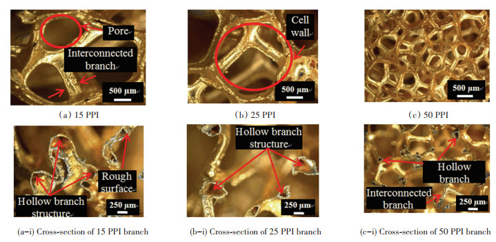
Additionally, the results proved that σmax would be reduced with the increase of pore density of porous Cu. 50 PPI porous Cu had more pores than its 15 PPI counterpart since the former had a higher pore density than the latter. Even though the pore size of 50 PPI porous Cu was smaller, it had a high number of cell walls that were interconnected with small diameter branches as displayed in Fig. 3. This structure gave off a large surface area for contact between Cu and porous Cu. However, this large surface area for 50 PPI porous Cu was not a decisive factor to form a strong bond due to the small size of the interconnected branches. In addition, the low σmax of 50 PPI porous Cu compared with that of 15 PPI porous Cu are more susceptible to be influenced by the hollow structure of porous Cu interconnected branches. The molten filler had to spread out and fill in more hollow space for 50 PPI porous Cu interconnected branches. This phenomenon was a factor that σmax decreased with increasing pore density of porous Cu. Previous studies demonstrated a similar pattern in the relationship between shear strength and pore density. Wan et al.[17] conducted a shear test on porous metal fiber sintered sheet (PMFSS) with different porosities. The increasing porosity of PMFSS from 70% to 90% led to a significant drop in its shear strength from 7.7 MPa to 0.9 MPa.
|
Fig.3 Digital microscope image of porous Cu and cross-section of porous Cu interconnected branch |
2.2 Interfacial Behaviour of Brazed Cu/VZ 2250/Porous Cu
Fig. 4 shows backscattered electron (BSE) micrographs of Cu/VZ 2250/porous Cu (15 PPI, 25 PPI, and 50 PPI) joints that were bonded at brazing temperature of 660 ℃. The filler region was successfully formed at the brazed interface between Cu and porous Cu. However, imperfect brazed interface was spotted for Cu/50 PPI porous Cu which could be attributed to the structure of porous Cu interconnected branches. The filler can be spotted in the BSE image of Cu/50 PPI porous Cu, and it was found to be scattered on the diffusion layer and porous Cu surface. The dissolution of the interconnected branches of 50 PPI porous Cu can take place at a higher brazing temperature which affects the brazed joint[18].

|
Fig.4 BSE images of brazed Cu/VZ 2250/porous Cu interface at different porous Cu pore densities |
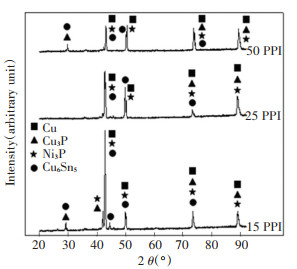
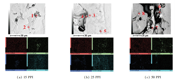
During brazing, the molten VZ 2250 migrated into Cu and porous Cu at an elevated temperature. This process led to the formation of IMC through interfacial reaction. EDX and XRD analysis were carried out to investigate the presence of IMC in the brazed joint. The XRD peak pattern of Cu (ICSD with PDF No. 98-062-7113), Cu3P (ICSD with PDF No. 98-062-8629), Ni3P (ICSD with PDF No. 98-064-6109), and Cu6Sn5 (ICSD with PDF No.98-010-6530) are visible in Fig. 5. The Cu has become a dominant peak as all Cu peaks appeared at 2 Theta of 43.33°, 50.46°, 74.15°, and 89.97°, which is the same as those in the XRD peak pattern list of Cu. The presence of Cu can be traced from the Cu substrate and VZ 2250. Next, the solely individual of Cu6Sn5 peak was detected at 2 Theta of 44.84°, which is stronger than all of the overlapped peaks of Cu6Sn5. On the other hand, the individual peaks of Ni3P and Cu3P were not observable due to overlapping with other phases. However, EDX mapping analysis proved the existence of Cu3P and Ni3P. Ni and P were found to be concentrated at the filler region for all porous Cu. This EDX reading corroborated the Cu3P and peak Ni3P from the XRD results.
|
Fig.5 XRD pattern of Cu/VZ 2250/porous Cu fractured surface with different porous Cu pore densities of 15 PPI, 25 PPI, and 50 PPI |
The filler region of brazed Cu/porous Cu seam with VZ 2250 contained high P concentration at points of 1, 2, 3, and 8 (Table 1) as displayed in Fig. 6. P has excellent solubility in porous Cu which caused the formation of Cu3P phase[19]. Cu3P and Ni3P are commonly identified as a brittle phase and from the mapping analysis P and Ni were concentrated in the filler region, while Sn was bound near the cavities from the mapping analysis. During the brazing process, the low melting point and active element of Sn tended to diffuse out from VZ 2250 filler and flow into a porous Cu. The reaction between Sn and Cu was the basis for the Cu6Sn5 liquid phase, which tended to diffuse around cavities.
| Table 1 Atomic percentage of elements from EDX analysis for Fig. 6 |
|
Fig.6 Elemental composition and mapping analysis of Cu/VZ 2250/porous Cu interface with porous align="center" |
2.3 Fractured Surface of Cu/VZ 2250/Porous Cu
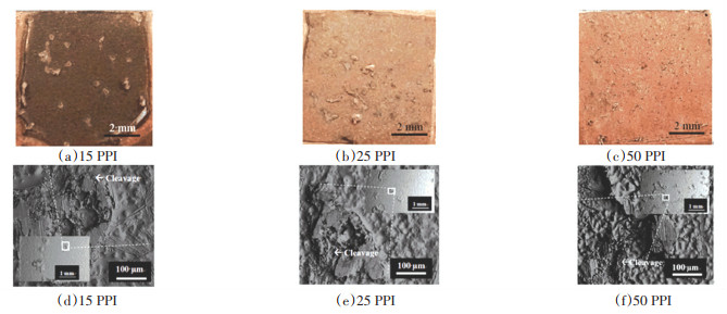
The fractured surfaces of Cu/VZ 2250/porous Cu/Cu joint bound at 660 ℃ with 15 PPI, 25 PPI, and 50 PPI porous Cu were analysed. Fig. 7(a-c) and Fig. 7(d-f) show their macroscopic and microscopic images, respectively, from the top view of the fractured surface of Cu/VZ 2250/porous Cu. Fig. 7(a-c) and inset of Fig. 7 (d-f) prove that the surface became rougher with a greater proliferation of patch marks as the PPI of the porous Cu was increased. The 50 PPI porous Cu tended to break at interconnected branch region instead of in the middle of the brazed interface. The smaller size of 50 PPI porous Cu interconnected branch contributed to shear fracture taking place at interconnected branch region.
|
Fig.7 Macroscopic (a-c) and microscopic (d-f) fractured surface of Cu/VZ 2250/porous Cu from the top view |
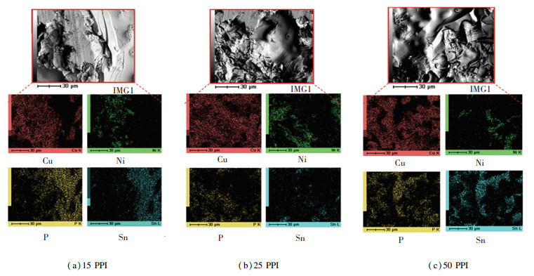
The side view of the fractured specimen from the shear test (Fig. 8) shows that the crack was initiated at the filler region and then followed by the diffusion region of the brazed interface. The brazed interface at the filler region implies that the filler region has a low resistance towards crack initiation. The crack was found to propagate along the brazed interface of the P and Ni. The noticeable P and Ni elements in mapping analysis of shear-fracture (Fig. 9) conformed the brazed interface failed at the filler region and diffusion region. However, it is worth noting that the filler region and diffusion region on the side view fracture specimens (Fig. 8) cannot be specified as the brazed interface between Cu and porous Cu. It may be a filler region and diffusion region on the porous Cu interconnected branch because of the ability of AF to diffuse into porous Cu. This can be proved by the discovery of the phosphide and nickel phases in mapping analysis (Fig. 9) on the patch mark (interconnected branch).

|
Fig.8 Fractured surface of Cu/VZ 2250/porous Cu from the side view with porous Cu |
|
Fig.9 Mapping analysis of shear-fracture of Cu/VZ 2250/porous Cu at brazing temperature of 660 ℃ |
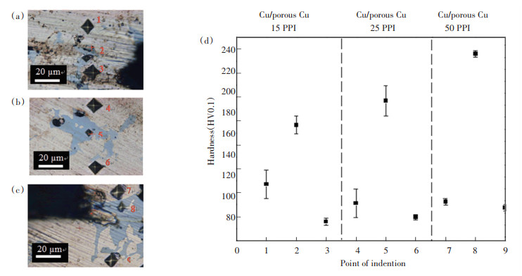
The indentation marks and hardness value (HV) for Cu/VZ 2250/porous Cu are shown in Fig. 10. According to Fig. 10(d), the HV for diffusion region was lower than filler region. This evidence was in accordance with the crack initiation at the filler region followed by the crack propagation at the diffusion region. Besides, the HV increased with increasing PPI porous Cu for each region (diffusion region and filler region) due to the smaller interconnected branches of porous Cu. This result was in line with the recorded lower shear strength for high pore density of porous Cu. The diffused area between Cu and porous Cu reflected similar HV due to the migration of IMC into the area. This similarity of HV was reported by Lutfi et al.[19] for brazed Cu/Cu. However, the HV in filler region was distinct due to the structural differences between porous Cu and solid Cu because the size of the porous Cu interconnected branches still played a crucial role even though the filler may have covered its surface.
|
Note: Diffusion region of porous Cu interface: Point 1, 4, 7; Filler region of Cu/porous Cu joint interface: Point 2, 5, 8; Diffusion region of Cu substrate interface: Point 3, 6 & 9 Fig.10 Indentation marks for porous Cu pore density of (a) 15 PPI (b) 25 PPI (c) 50 PPI and (d) HV of Cu/VZ 2250/porous Cu |
3 Conclusions
This study showed the characteristics of brazed Cu/porous Cu joint with VZ 2250 filler metal. The strength of the brazed joint was evaluated from the shear and micro-hardness tests. In addition, the fractured surface and microstructure around the interface joint were analysed. The maximum shear strength for Cu/porous Cu was recorded at brazing temperature of 660 ℃ for all PPI porous Cu. An increase in the brazing temperature compromised the shear strength due to the formation of large microstructure and failure of porous Cu interconnected branch. The brittle phases of Cu3P and Ni3P were discovered at the filler region, while Cu6Sn5 was bound near the cavities. The high pore density porous Cu was discovered to leave more patch mark on Cu after shear test compared with low pore density of porous Cu. Porous Cu with higher pore density experienced fracture with more brittle cleavage and lower shear strength. Finally, the filler region reflected an increasing HV as the pore density was increased due to the structure of porous Cu interconnected branches. Overall, the results showed that porous Cu with lower pore density had better performance in terms of joint strength.
| [1] |
Abadi G B, Kim D Y, Yoon S Y, et al. Thermal performance of a 10-kW phase-change plate heat exchanger with metalfoam filled channels. Applied Thermal Engineering, 2016, 99: 790-801. DOI:10.1016/j.applthermaleng.2016.01.156 (  0) 0) |
| [2] |
Abadi G B, Moon C, Kim K C. Experimental study on single-phase heat transfer and pressure drop of refrigerants in a plate heat exchanger with metal-foam-filled channels. Applied Thermal Engineering, 2016, 102: 423-431. DOI:10.1016/j.applthermaleng.2016.03.099 (  0) 0) |
| [3] |
Hu H T, Weng X M, Zhuang D W, et al. Heat transfer and pressure drop characteristics of wet air flow in metal foam under dehumidifying conditions. Applied Thermal Engineering, 2016, 93: 1124-1134. DOI:10.1016/j.applthermaleng.2015.09.019 (  0) 0) |
| [4] |
Shirzadi A A, Kocak M, Wallach E R. Joining stainless steel metal foams. Science and Technology of Welding and Joining, 2004, 9(3): 277-279. DOI:10.1179/136217104225012210 (  0) 0) |
| [5] |
Zhao C Y. Review on thermal transport in high porosity cellular metal foams with open cells. International Journal of Heat and Mass Transfer, 2012, 55(13-14): 3618-3632. DOI:10.1016/j.ijheatmasstransfer.2012.03.017 (  0) 0) |
| [6] |
Tadrist L, Miscevic M, Rahli O. About the use of fibrous materials in compact heat exchangers. Experimental Thermal and Fluid Science, 2004, 28(2-3): 193-199. DOI:10.1016/S0894-1777(03)00039-6 (  0) 0) |
| [7] |
Haack D P, Butcher K R, Kim T, et al. Novel Lightweight Metal Foam Heat Exchangers. https://www.researchgate.net/publication/267721239_Novel_Lightweight_Metal_Foam_Heat_Exchangers, 2020-10-22.
(  0) 0) |
| [8] |
Tan W C, Chong K K. Simplification of heat transfer modelling for 3-D open cell copper foam by using single-direction aligned cylinder-bank geometry. Applied Thermal Engineering, 2016, 107: 1192-1200. DOI:10.1016/j.applthermaleng.2016.07.035 (  0) 0) |
| [9] |
Lunsford K M. Advantages of Brazed Heat Exchangers in the Gas Processing Industry. http://bre.com/PDF/Advantages-of-Brazed-Heat-Exchangers-in-the-Gas-Processing-Industry.pdf, 2020-10-20.
(  0) 0) |
| [10] |
Boomsma K, Poulikakos D, Zwick F. Metal foams as compact high performance heat exchangers. Mechanics of Materials, 2003, 35(12): 1161-1176. DOI:10.1016/j.mechmat.2003.02.001 (  0) 0) |
| [11] |
Hasap A, Noraphaiphipaksa N, Kanchanomai C. The Microstructure and Strength of Copper Alloy Brazing Joints. Welding Journal, 2014, 93(4): 116-123. (  0) 0) |
| [12] |
Serban V A, Codrean C, Utu D, et al. Amorphous alloys for brazing copper based alloys. Journal of Physics: Conference Series, 2009, 144: 012098. DOI:10.1088/1742-6596/144/1/012098 (  0) 0) |
| [13] |
Yu W Y, Lu W J, Xia T D. Formation process of joints brazing with amorphous filler metal. Rare Metal Materials and Engineering, 2013, 42(4): 688-691. DOI:10.1016/S1875-5372(13)60057-0 (  0) 0) |
| [14] |
Maisarah L, Yusof F, Ramesh S, et al. A novel method of brazing Cu/Cu-7.0Ni-9.3Sn-6.3P/Cu using microwave hybrid heating. Materialwissenschaft Und Werkstofftechnik, 2017, 46(3-4): 299-305. DOI:10.1002/mawe.201600780 (  0) 0) |
| [15] |
Shah R K, Sekulić D P. Fundamentals of Heat Exchanger Design. Hoboken, New Jersey: John Wiley & Sons, 2003. DOI:10.1002/9780470172605
(  0) 0) |
| [16] |
Hudson Products Corporation. The Basic of Air-cooled Heat Exchangers. https://files.chartindustries.com/hudson/Basics of ACHEBrochure-Web.pdf, 2020-10-20.
(  0) 0) |
| [17] |
Wan Z P, Liu B, Zhou W, et al. Experimental study on shear properties of porous metal fiber sintered sheet. Materials Science and Engineering A, 2012, 544: 33-37. DOI:10.1016/j.msea.2012.02.070 (  0) 0) |
| [18] |
Jacobson D M, Humpston G. Principles of Brazing. Ohio: ASM International, 2005.212.
(  0) 0) |
| [19] |
Lutfi M, Yusof F, Ariga T, et al. Interfacial reaction analysis of Cu-Sn-Ni-P/Cu joint using microwave hybrid heating. Key Engineering Materials, 2016, 701: 148-153. DOI:10.4028/www.scientific.net/KEM.701.148 (  0) 0) |
 2022, Vol. 29


