2. Gree Electric Appliances, Inc. of Zhuhai, Zhuhai 519070, Guangdong, China;
3. National Key Laboratory of Science and Technology on Helicopter Transmission, Nanjing University of Aeronautics and Astronautics, Nanjing 210016, China
The sprag clutch has the characteristics of low manufacturing cost, high power density, excellent durability, and reliability, which is widely used in the current industrial field. The driveshaft is often used directly as the outer ring of the sprag clutch, and the driven shaft is directly used as the inner ring, which together form a sprag clutch-rotor system to make the structure more compact.
Scholars have developed a lot of research on clutch components, including the establishment of static and dynamic engaging models, dynamic engaging characteristics analysis, and experimental verification. Since the 1970s, many scholars began to propose the static iterative model of the sprag clutch and carry out experimental verification[1-3]. On this basis, multi-body and finite element dynamic models of the sprag clutch considering various factors have been established, and various dynamic characteristics analysis and experimental verification have been promoted[4-9].
For the actual sprag clutch-rotor system, the sprag clutch is usually located between two inter-shaft rolling bearings. The sprag clutch transmits the torque between the inner and outer rotors, so it can be considered as a special inter-shaft bearing. Therefore, the research on the sprag clutch-rotor system can refer to the inter-shaft bearing-rotor system. Because of the existence of engaging and overrunning conditions of the sprag clutch, the dynamic characteristics of the sprag clutch-rotor system are more complex than that of the inter-shaft bearing-rotor system. Concerning the inter-shaft bearing-rotor system, different modeling methods have been used to study the vibration characteristics of the system. The commonly used modeling methods include the Jeffcott method, the transfer matrix method, and the finite element method. Among them, the finite element has higher precision, is easy to program, has good versatility and scalability, and is especially suitable for solving rotor systems with complex structures.
Nelson[10] derived the matrix expressions of Rayleigh beam elements and Timoshenko beam elements, and introduced the finite element method into the dynamic analysis of the rotor system for the first time. Chiang et al.[11] established a dual-shaft turbine rotor system model using the finite element method, focusing on the influence of the rotor revolution ratio and the inner-shaft bearing stiffness on the critical speed. Guskov et al.[12] built a coaxial double rotor system test-bed in which the inner and outer rotors were coupled through an inter-shaft bearing, and the effects of rotor revolution ratio on critical speed and rotor vibration amplitude was measured and compared with the finite element model. Chen[13] used a uniform cross-section Euler beam element to discretize the rotor, and considered the bearing clearance, squeeze film damper, and the collision between the rotor and the casing, and established a finite element model of the rotor-bearing-casing to simulate the vibration characteristics of aero-engine, and analyzed the influence of bearing and squeeze film damper parameters on system response. Fei[14] derived the finite element model of the inter-shaft bearing-double rotor system, used the complex modal theory of the state space to solve the critical speed, and analyzed the influence of the gyro torque and the ratio of inner and outer shaft speed on the dynamic response. Chen[15] deduced the force and torque expressions of ball bearings and cylindrical roller bearings with five-degree-of-freedom. Based on the finite element theory, a six-degree-of-freedom rotor-bearing-casing coupling vibration model was established, and the natural characteristics of the system were analyzed. Compared with the test results, the first three-order natural frequency error is within 5%. Hong et al.[16] established the vibration model of aero-engine dual rotors using the finite element method, and derived the expression of the fulcrum dynamic load, and analyzed the influence of unbalance, rotor bending deformation, and wheel inertia load on the dynamic load of the fulcrum under different rotating speeds, and put forward the optimization method of fulcrum vibration response. Wang et al.[17] used a one-dimensional Timoshenko beam element and a three-dimensional finite element to discretize the rotors and established a model of a dual-rotor system with inter-shaft bearings. It was found that the two discrete methods were highly consistent in terms of critical speed and mode shapes, and the one-dimensional model takes less time. Then, the working deformation trajectory and unbalanced response analysis were carried out, and the correctness of the finite element model is verified by comparison with the experiment. Lu et al.[18] built the finite element model of a dual-rotor-bearing system and analyzed the effects of the bearing clearance on the time-varying stiffness and primary resonance behaviors. Cheng et al.[19] presented a model to study the dynamic characteristics of a rotor-bearing-coupling system and analyzed the effects of typical parameters on mechanical properties and nonlinear dynamic responses of the rotor system.
The above researches are all aimed at the inter-shaft bearing-rotor system, and there are few reports on the research on the sprag clutch-rotor system[20]. Although the FE model of the sprag clutch-rotor system was established in Ref. [20] and the natural characteristics were analyzed, the establishment of the stiffness element of the sprag clutch only considered the torsional stiffness. The analysis of the vibration characteristics was not in-depth and the model test verification had not been carried out.
The sprag clutch-rotor system tends to rotate at a high speed under steady-state engaging working conditions, while the inner and outer rotors will produce elastic deformation and vibration in the bending direction, and the bearings are flexible supports. Besides, as an inter-shaft support component, the sprag clutch couples the vibrations in the torsion and bending directions of the inner and outer rotors, which makes the overall vibration characteristics of the system more complicated. For describing the vibration characteristics of the sprag clutch-flexible rotor system, the main work of this paper is to establish a dynamic model in Section 2, which can simultaneously describe the bending, axial and torsional coupled vibrations, and to study the system vibration characteristics in Section 3 based on this model.
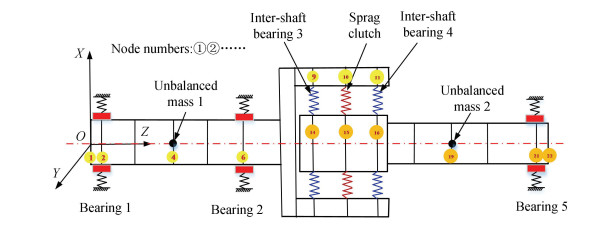
1 Finite Element Model of SC-FRSThe division of the finite element units of the sprag clutch-rotor system is shown in Fig. 1. The outer rotor is divided into 11 beam elements with node numbers from 1 to 12; the inner rotor is divided into 9 beam elements with node numbers from 13 to 22. The angular contact bearings 1 and 2 of the outer rotor are respectively located at nodes 2 and 6, the outer ring of the bearing is fixed, and the inner ring is fixedly connected to the corresponding nodes. The outer rings of the inter-shaft bearings 3 and 4 are fixedly connected to nodes 9 and 11, respectively, and the inner ring is fixedly connected to nodes 14 and 16. The deep groove ball bearing 5 is located on node 21, the outer ring is fixed, and the inner ring is fixed with node 21. The outer ring of the sprag clutch is the outer rotor, and the inner ring is the inner rotor, which connects node 10 of the outer rotor and node 15 of the inner rotor.
|
Fig.1 Schematic diagram of the division for the finite element unit of the system |
In the finite element model of the sprag clutch-rotor system, the inner and outer rotors are flexible with Timoshenko beam elements, and the method of establishing the stiffness element of the support bearing is shown in Ref. [20]. This section focuses on the establishment method of the six-degree-of-freedom stiffness element for the sprag clutch.
As shown in Fig. 2, the relative displacement vector of the inner and outer rotors is defined as
| $ \boldsymbol{\delta}_{s}=\left[\Delta \delta_{s x}, \Delta \delta_{s y}, \Delta \gamma_{s x}, \Delta \gamma_{s y}, \Delta \gamma_{s z}\right]^{\mathrm{T}} $ | (1) |

|
Fig.2 Coordinate system and degrees of freedom of the sprag clutch |
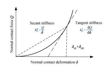
Due to the preload torque, there are pre-contact deformations δHI and δHE in the radial direction between the inner and outer rotors and the sprag roller respectively, which makes the contact area produce pre-stress rigidity and results in an increase of actual contact stiffness. The actual stiffness coefficient can be obtained according to the pre-contact deformations and corresponding load shown in Fig. 3, and the calculation method of δHI and δHE can be found in Ref. [9].
|
Fig.3 Tangential stiffness corresponding to pre-contact deformation |
For the j-th sprag roller of the sprag clutch, according to the Hertzian contact theory, the relationship between the normal force Qj and the vibration displacement δj of the inner and outer rotors is obtained:
| $ Q_{j}=k_{n}^{t}\left(\delta_{j}\right)^{n} $ | (2) |
For cylindrical contact, the exponent n of δj in the formula is equal to 10/9.
Under the action of preloading torque, when there is a radial displacement δr between the inner and outer rotors, the normal deformation δjr of the sprag roller at any angular position Ψi is
| $ \delta_{j r}=\delta_{r} \cos \psi_{j} $ | (3) |
When the inner and outer rotors have an angular displacement Δγsz in the torsional direction, the normal deformation of the sprag roller at any angular position is
| $ \delta_{j t}=\varDelta_{r}^{t}=d_{t} \varDelta \gamma_{s z} $ | (4) |
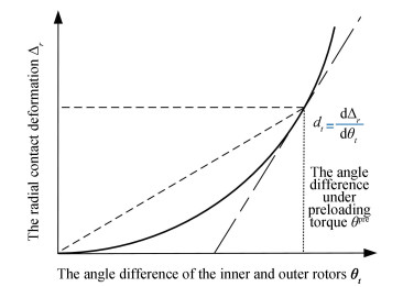
where Δrt is the total radial contact deformation caused by the torsional angular displacement Δγsz under the preloading torque, dt is the deformation coefficient which can be obtained from the angle difference of the inner and outer rotors and the corresponding total radial contact deformation as shown in Fig. 4.
|
Fig.4 Radial deformation coefficient under preloading torque |
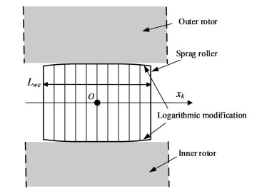
After the axial modification of the sprag roller by the logarithmic function[10], the influence of the axial modification of the sprag roller on the contact deformation should be considered. As shown in Fig. 5, the sprag roller is divided into ns slices along the length direction, and the center coordinate of the k-th sprag roller is
| $ x_{k}=\frac{n_{s}+1-2 k}{2} \cdot \frac{L_{w e}}{n_{s}} $ | (5) |
|
Fig.5 Division of the slices in the axial direction of the sprag roller |
The normal deformation between the rotor and the sprag roller caused by the modification of the sprag roller is
| $ \delta_{j L}=-2 L\left(x_{k}\right) $ | (6) |
where L(xk) is the modification value, which can be calculated by Eq. (1) in Ref. [10].
After modification, there is an angular displacement around the radial direction between the outer and inner rotors. The normal comprehensive deformation of the contact area caused by this angular displacement is
| $ \delta_{j \theta}=-x_{k} \theta \cos \psi_{j} $ | (7) |
Therefore, the comprehensive deformation of the k-th slice of the j-th sprag roller can be obtained as follows:
| $ \begin{aligned} \delta_{j k}&=\delta_{j r}+\delta_{j t}+\delta_{j L}+\delta_{j \theta}=\delta_{r} \cos \psi_{j}+d_{t} \Delta \gamma_{s z}-2 L\left(x_{k}\right)- \\ &x_{k} \theta \cos \psi_{j} \end{aligned} $ | (8) |
Summing the comprehensive deformations of all the contacting slices into Eq. (2), the force and torque of the rotor at the clutch position can be obtained:
| $ \left\{\begin{array}{l} F_{r}=\frac{k_{n}^{t}}{n_{s}} \sum\limits_{j=1}^{Z}\left[\sum\limits_{k=1}^{n_{s}}\left[\left(\delta_{j, k}\right)^{n} \cos \psi_{i}\right]\right] \\ M=\frac{k_{n}^{t}}{n_{s}} \sum\limits_{j=1}^{Z}\left[\sum\limits_{k=1}^{n_{s}}\left[-x_{k}\left(\delta_{j, k}\right)^{n} \cos \psi_{i}\right]\right] \end{array}\right. $ | (9) |
The deformation δr and θ are represented by the components of δs, and the force and torque are decomposed in the direction of the components of δs, and the relationship between load and deformation of the sprag clutch under preloading torque is obtained as follows:
| $ \boldsymbol{P}_{s}=\boldsymbol{K}_{p s} \boldsymbol{\delta}_{s} $ | (10) |
where Kps is the 5-degree-of-freedom stiffness matrix of the sprag clutch. By extending the 5-degree-of-freedom stiffness matrix to 6 degrees of freedom, the expression of the stiffness matrix of the sprag clutch unit in the system is obtained:
| $ \boldsymbol{K}_{s}=\left[\begin{array}{cccccc} \frac{\partial F_{s x}}{\partial \varDelta \delta_{s x}} & \frac{\partial F_{s x}}{\partial \varDelta \delta_{s y}} & 0 & \frac{\partial F_{s x}}{\partial \varDelta \gamma_{s x}} & \frac{\partial F_{s x}}{\partial \varDelta \gamma_{s y}} & \frac{\partial F_{s x}}{\partial \varDelta \gamma_{s z}} \\ \frac{\partial F_{s y}}{\partial \varDelta \delta_{s x}} & \frac{\partial F_{s y}}{\partial \varDelta \delta_{s y}} & 0 & \frac{\partial F_{s y}}{\partial \varDelta \gamma_{s x}} & \frac{\partial F_{s y}}{\partial \varDelta \gamma_{s y}} & \frac{\partial F_{s y}}{\partial \varDelta \gamma_{s z}} \\ 0 & 0 & 0 & 0 & 0 & 0 \\ \frac{\partial M_{s x}}{\partial \varDelta \delta_{s x}} & \frac{\partial M_{s x}}{\partial \varDelta \delta_{s y}} & 0 & \frac{\partial M_{s x}}{\partial \varDelta \gamma_{s x}} & \frac{\partial M_{s x}}{\partial \varDelta \gamma_{s y}} & \frac{\partial M_{s x}}{\partial \varDelta \gamma_{s z}} \\ \frac{\partial M_{s y}}{\partial \varDelta \delta_{s x}} & \frac{\partial M_{s y}}{\partial \varDelta \delta_{s y}} & 0 & \frac{\partial M_{s y}}{\partial \varDelta \gamma_{s x}} & \frac{\partial M_{s y}}{\partial \varDelta \gamma_{s y}} & \frac{\partial M_{s y}}{\partial \varDelta \gamma_{s z}} \\ \frac{\partial M_{s z}}{\partial \varDelta \delta_{s x}} & \frac{\partial M_{s z}}{\partial \varDelta \delta_{s y}} & 0 & \frac{\partial M_{s z}}{\partial \varDelta \gamma_{s x}} & \frac{\partial M_{s z}}{\partial \varDelta \gamma_{s y}} & \frac{\partial M_{s z}}{\partial \varDelta \gamma_{s z}} \end{array}\right] $ | (11) |
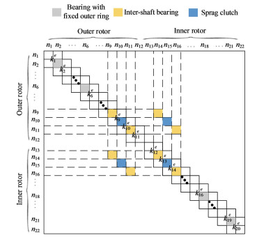
Transforming each finite element unit into the unified coordinate system and describing it with generalized degrees of freedom, the global stiffness matrix of the system can be assembled as shown in Fig. 6, where ni is the node number and kie is the element stiffness matrix of the node. According to the set method of stiffness matrix, the whole mass matrix and gyroscope matrix of the system can be assembled. Considering the dynamic excitation force, the motion equation of the entire system can be obtained[20]. The damping matrix is calculated according to the Rayleigh formula. The coefficients in the Rayleigh formula can be determined by calculating the natural frequency and damping ratio.
|
Fig.6 Schematic diagram of the assembly of the stiffness matrix |
2 Vibration Characteristics of SC-FRS 2.1 Natural Characteristics of SC-FRS
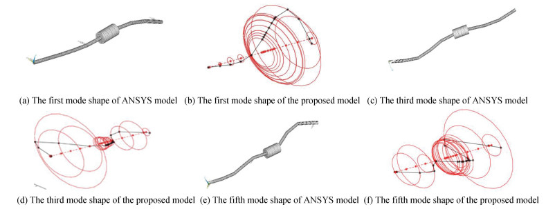
At the speed of 5000 r/min, the SC-FRS model proposed in this paper and the ANSYS model are used to calculate the natural frequency, mode shape, and critical speed. The ANSYS finite element model is established by using APDL, and six degrees of freedom Timoshke beam element is used in modeling. The first 6-order natural frequencies calculated by each model are given in Table 1. It can be seen from the table that the relative errors of the first 6-order natural frequencies calculated by the proposed model in this paper and ANSYS are all within 0.3%. As shown in Fig. 7, the mode shapes of the first, third, and fifth orders of the system calculated by the two models are highly consistent. The comparison results of natural frequencies and modal shapes verify the correctness of the SC-FRS finite element model.
| Table 1 Natural frequency of rotor system calculated by various models |
|
Fig.7 The representative mode shapes of ANSYS model and proposed model |
Fig. 8 shows the Campbell diagram of the system, in which the first critical speed is 10149 r/min, the third critical speed is 32298 r/min, and the fifth critical speed is 36245 r/min.

|
Fig.8 Campbell diagram of rotor system with the sprag clutch |
2.2 Unbalanced Response of SC-FRS
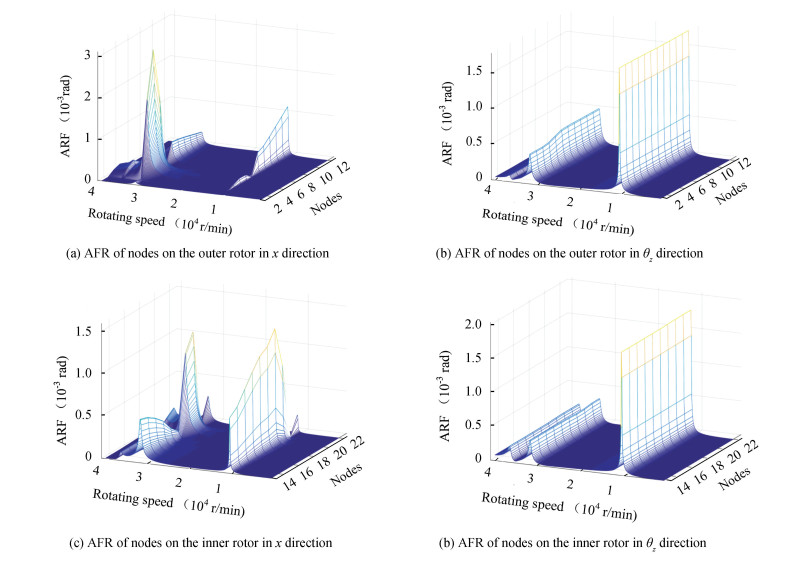
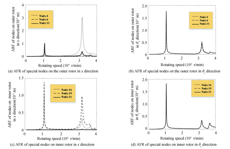
The unbalanced response analysis of SC-FRS is performed by assigning the 1.4×10⁻⁵ kg·m to the unbalanced mass 1 on node 4, and 1×10⁻⁵ kg·m to the unbalanced mass 2 on node 19. Fig. 9 shows the amplitude-frequency response of the nodes of the outer rotor and inner rotor in the x and θz directions. Since the representativeness of vibration responses of the nodes where the unbalanced mass and inter-shaft bearings are located, the amplitude-frequency response curve is extracted, as shown in Fig. 10. Fig. 10 shows the amplitude-frequency response curves of node 4, node 6, and node 11 in the x and θz directions on the outer rotor, and the amplitude-frequency response curves of node 16, node 19, and node 21 in the x and θz directions on the inner rotor.
|
Fig.9 ARF of nodes on the rotors |
|
Fig.10 ARF of special nodes on the rotors |
It can be seen from Fig. 9 and Fig. 10 that when the working speeds of the inner and outer rotors are equal to the first, third, and fifth-order critical speeds, resonance peaks appear at all nodes in the x and θz directions. In the θz direction of the outer rotor, the torsional amplitudes of each node on a single resonant peak are almost equal. Among the resonance peaks, the amplitude corresponding to the first critical speed is the highest, which is significantly higher than the third and fifth critical speeds. In the θz direction of the inner rotor, the conclusion is consistent with that of the outer rotor.
Compared with the resonance peak of each node in θz direction, the amplitude difference of each node in x direction is very obvious. At the first critical speed in x direction of the outer rotor, the vibration amplitude of node 11 where the inter-shaft bearing 4 is located is the highest, and the relative amplitude of each node is similar to the first-order mode shape. At the third and fifth-order critical speeds, the vibration amplitude of the node 11 where the unbalanced mass 1 is located is the highest, and the relative amplitude of each node is similar to the third and fifth-order mode shapes. In all the resonance peaks, the amplitudes of node 2 and node 6 are significantly lower than the other nodes due to the limitation of bearings 1 and 2 fixed on the outer ring.
In x direction of the inner rotor, the resonance peak amplitude of each node 13 to 19 at the first critical speed is significantly higher than the corresponding amplitude of the other resonance peaks. Meanwhile, the amplitude of node 19 where the unbalanced mass 2 is located is the highest in all resonance peaks, and the amplitude of the node where the support bearing is located is obviously lower than that of the other nodes.
In summary, the response of SC-FRS shows the properties of coupled bending and torsional vibration, and the amplitude-frequency response of each node of the inner and outer rotors is mainly affected by the modal shape, the location and size of the unbalanced mass, and the bearing support position.
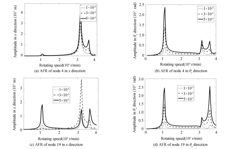
The unbalanced mass 1 on node 4 is assigned 1.4×10⁻⁵ kg·m, and the unbalanced mass 2 on node 19 is assigned 1×10⁻⁵ kg·m, 3×10⁻⁵kg·m, and 5×10⁻⁵ kg·m respectively for studying the influence of unbalance on the vibration amplitude of nodes 4 and 19 with prominent amplitude. The calculated amplitude- frequency response (AFR) curves of node 4 and node 19 in x direction and θz direction are shown in Fig. 11. It can be seen that in x direction and θz direction of node 4, the amplitudes of each resonance peak increase rapidly with the increase of unbalanced mass; in x direction of node 19, the resonance peaks corresponding to the first and fifth critical speeds increase with the increase of unbalanced mass 2. When the value of unbalanced mass 2 is 3×10⁻⁵ kg·m, the amplitude of resonance peak corresponding to the third critical speed is larger than that of 5×10⁻⁵ kg·m. Besides, the amplitudes of each resonance peak in x and θz directions of node 4 and node 19 increase rapidly with the increase of unbalanced mass.
|
Fig.11 ARF of nodes under unbalanced mass 2 |
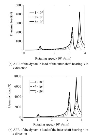
The inter-shaft bearings 3 and 4 can provide a stable axial engaging for the sprag clutch. However, due to the deformation of the outer and inner rotors, the dynamic loads of inter-shaft bearings are complex. It is necessary to analyze the dynamic loads of inter-shaft bearings for preventing the failure caused by excessive load. Fig. 12 describes the amplitude-frequency response of the dynamic loads of the inter-shaft bearings 3 and 4 under different unbalanced mass 2.
|
Fig.12 ARF of the dynamic load of the inter-shaft bearings under unbalanced mass 2 |
As shown in the figure, there are resonance peaks at the first, third, and fifth critical speeds of inter-shaft bearings 3 and 4. Under the same unbalanced mass, the resonance amplitude of the high-order critical speed is higher than that of the low-order critical speed. At the same time, the dynamic load of inter-shaft bearing 4 is higher than that of inter-shaft bearing 3. With the increase of unbalanced mass 2, the amplitudes of inter-shaft bearing 3 and 4 at each resonance peak increase.
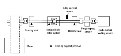
2.3 Experimental Verification Based on Unbalanced ResponseThe test schematic diagram is shown in Fig. 13, and the test system is mainly composed of the sprag clutch-rotor system test-bench, drive system, load system, data acquisition, and analysis system.
|
Fig.13 Schematic of the test bench of sprag clutch-rotor system |
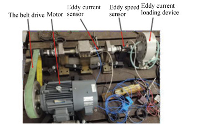
Fig. 14 is a physical diagram of the sprag clutch-rotor system, and its actual structure is consistent with Fig. 1. At the position of the node 4 and the node 19, the unbalanced masses are 7×10⁻⁵ kg·m and 6×10⁻⁵ kg·m, respectively.
|
Fig.14 The test bench of sprag clutch-rotor system |
The finite element model of the sprag clutch-rotor system proposed in this paper is used to calculate the axis trajectories of the measurement points at different speeds, and the results are compared with the experimental measurement results. Fig. 15 shows the theoretical and experimental results of the axis trajectory at a speed of 7000 r/min and a load of 15 N·m. It can be seen from the figure that under the action of unbalanced excitation, the axis trajectory of the sprag clutch-rotor system is approximately elliptical, and the theoretical calculation results are similar to the experimental results, so the theoretical calculation method proposed in this paper can accurately describe the axis trajectory of the sprag clutch-rotor system under unbalanced excitation.

|
Fig.15 Axis trajectory of model calculation and test measurement at 7000 r/min |
Fig. 16 shows the relationship between the rotation speed of the SC-FRS and the vibration displacement in x direction. As shown in the figure, the difference between the theoretically calculated first-order critical speed (10149 r/min) and the experimental critical speed is very small, and the resonance peak value is close. Therefore, the SC-FRS finite element model established in this paper has high accuracy.

|
Fig.16 Comparison of critical speed of SC-FRS between theoretical calculation and experiment of x direction |
3 Conclusions
In order to describe the vibration characteristics of the sprag clutch-flexible rotor system, a system dynamic model was established, which can simultaneously describe the bending, axial and torsional coupling vibrations. Based on this model, the vibration characteristics of the system were analyzed, which provided theoretical guidance for the dynamic design of the sprag clutch components.
1) A calculation method for the 6-DOF stiffness matrix of the sprag clutch is proposed, and the SC-FRS finite element model is established by integrating the inner and outer rotors and bearing units. Through the comparison of natural frequencies, it is found that the relative error for the first 6-order natural frequencies between the proposed model in this paper and the ANSYS model is within 0.3%.
2) Under the unbalanced excitation of the outer rotor and inner rotor, the amplitude-frequency response of each node in the bending direction and torsion direction is analyzed. The results show that the relative size at the resonance peak for each node is very sensitive to the magnitude of the unbalanced mass, and it increases rapidly with the increase of the unbalanced mass. At the same time, at each critical speed, resonance peaks appear at each node in the bending direction and torsion direction, which reflects the bending and torsion coupling vibration characteristics of the whole system.
3) The amplitude-frequency response of the dynamic load of the inter-shaft bearing under different unbalanced masses is analyzed. It is found that the dynamic load of the left and right inter-shaft bearings increases rapidly with the increase of the unbalanced mass, and the dynamic load of the right inter-shaft bearing is higher than that of the left inter-shaft bearing.
| [1] |
Lynwander P, Meyer A G, Chachakis S. Sprag overriding aircraft clutch. Fort Eustis: U.S. Army Air Mobility Research and Development Laboratory, 1972.
(  0) 0) |
| [2] |
Ayoub N J, Perin W G. Test Results and Technology Development Report-HLH/ATC Transmission Overrunning Clutch. Fort Eustis: U.S. Army Air Mobility Research and Development Laboratory, 1974.
(  0) 0) |
| [3] |
Kish J. Helicopter Freewheel Unit Design Guide. Fort Eustis: Applied Technology Laboratory, U.S. Army Research and Technology Laboratories, 1977.
(  0) 0) |
| [4] |
Xu T, Lowen G G. A mathematical model of an over-running sprag clutch. Mechanism and Machine Theory, 1994, 29(1): 11-23. DOI:10.1016/0094-114X(94)90016-7 (  0) 0) |
| [5] |
Vernay P, Ferraris G, Delbez A, et al. Transient behaviour of a sprag-type over-running clutch: an experimental study. Journal of Sound Vibration, 2001, 248(3): 567-572. DOI:10.1006/jsvi.2001.3700 (  0) 0) |
| [6] |
Liu Z H, Yan H Z, Cao Y M. Design and analysis of logarithmic spiral type sprag one-way clutch. Journal of Central South University, 2015, 22: 4597-4607. DOI:10.1007/s11771-015-3010-z (  0) 0) |
| [7] |
Yan H Z, Yang B, Hu K X, et al. Working performance analysis of positive-continuous-engagement type clutch in different friction conditions. Journal of Mechanical Engineering, 2010, 46(17): 86-92. (in Chinese) DOI:10.3901/JME.2010.17.086 (  0) 0) |
| [8] |
Huang C, Liu M, Zhao Y Q. An analytical model of multiarc sprag clutch considering geometry and internal interaction. Shock and Vibration, 2017, 2017: 2393578. DOI:10.1155/2017/2393578 (  0) 0) |
| [9] |
Huang C, Zhao Y Q, Liu M. Analytical modeling and optimization of logarithmic sprag clutch considering profile modification. Shock and Vibration, 2018, 2018: 4190303. DOI:10.1155/2018/4190303 (  0) 0) |
| [10] |
Nelson H D. A finite rotating shaft element using Timoshenko beam theory. Journal of Mechanical Design, 1980, 102(4): 793-803. DOI:10.1115/1.3254824 (  0) 0) |
| [11] |
Chiang H W, Hsu C N, Tu S H. Rotor-bearing analysis for turbomachinery single-and dual-rotor systems. Journal of Propulsion and Power, 2004, 20(6): 1096-1104. DOI:10.2514/1.3133 (  0) 0) |
| [12] |
Guskov M, Sinou J -J, Thouverez F, et al. Experimental and numerical investigations of a dual-shaft test rig with intershaft bearing. International Journal of Rotating Machinery, 2007, 2007: 75762. DOI:10.1155/2007/75762 (  0) 0) |
| [13] |
Chen G. A new rotor-ball bearing-stator coupling dynamics model for whole aero-engine vibration. Journal of Vibration and Acoustics, 2009, 131(6): 0610091-0610099. DOI:10.1115/1.4000475 (  0) 0) |
| [14] |
Fei Z X, Tong S G, Wei C. Investigation of the dynamic characteristics of a dual rotor system and its start-up simulation based on finite element method. Journal of Zhejiang University Science A, 2013, 14(4): 268-280. DOI:10.1631/jzus.A1200298 (  0) 0) |
| [15] |
Chen G. Whole aero-engine vibration coupling dynamics model including modeling of complex ball and roller bearings. Journal of Aerospace Power, 2017, 32(9): 2193-2204. (in Chinese) DOI:10.13224/j.cnki.jasp.2017.09.019 (  0) 0) |
| [16] |
Hong J, Li T R, Ni Y Y, et al. Bearing dynamic load model and optimal design of complex rotor system. Journal of Beijing University of Aeronautics and Astronautics, 2019, 45(5): 847-854. (in Chinese) DOI:10.13700/j.bh.1001-5965.2018.0484 (  0) 0) |
| [17] |
Wang N F, Jiang D X, Xu H Z. Dynamic characteristics analysis of a dual-rotor system with inter-shaft bearing. Proceedings of the Institution of Mechanical Engineers, Part G: Journal of Aerospace Engineering, 2019, 233(3): 1147-1158. DOI:10.1177/0954410017748969 (  0) 0) |
| [18] |
Lu Z Y, Zhong S, Chen H Z, et al. Nonlinear response analysis for a dual-rotor system supported by ball bearing. International Journal of Non-Linear Mechanics, 2021, 128: 103627. DOI:10.1016/j.ijnonlinmec.2020.103627 (  0) 0) |
| [19] |
Cheng H C, Zhang Y M, Lu W J, et al. Mechanical characteristics and nonlinear dynamic response analysis of rotor-bearing-coupling system. Applied Mathematical Modelling, 2021, 93: 708-727. DOI:10.1016/j.apm.2020.12.041 (  0) 0) |
| [20] |
Huang C, Zhao Y Q, Liu M, et al. Dynamic modelling and vibration analysis of dual-rotor system with inter-shaft sprag clutch and bearings. 2019 22nd International Conference on Electrical Machines and Systems. Piscataway: IEEE, 2019. 19213911. DOI: 10.1109/ICEMS.2019.8922474.
(  0) 0) |
 2022, Vol. 29


