2. UCL Cardiovascular Engineering Laboratory, University College London, London WC1E 6BT, United Kingdom
Since 1965, a Stewart platform with six degrees of freedom movement was developed by German scholar Stewart[1]. The motion simulator based on this platform structure has entered an era. Compared with serial mechanisms, such as mechanical arm, Stewart platforms have the feature of high rigidity, high precision, relatively small inertia, stable structure, and strong bearing capacity[2]. Thus, Stewart platforms get a high concern and attention since they are in use of practical applications, such as NASA vertical motion simulator[3], stabilized platform[4], spacecraft Omni-directional rendezvous[5], flight simulator[6], and Five-hundred-meter Aperture Spherical radio Telescope[7-8].
However, Stewart platforms can be titled as ±20~30 degrees in its workspace because of the character of parallel platform[9]. Most current flight simulators have applied Stewart platform as motion base. Jiang[10] used the Stewart platform with six degrees of freedom to analyze the kinematics of the general aviation simulator. Zhang[11] explored the overall coupling simulation effect of the improved algorithm on Stewart platform, and PID control and SimMechanics model were introduced for joint simulation. Du[12] designed a 6-DOF flight attitude simulation platform based on Stewart 6-DOF parallel mechanism inverse kinematics control algorithm, which transformed the flight attitude data into the motion control parameters of actuator. In order to enlarge rotation angle of flight simulator, much efforts have been conducted, for instance, a flight simulator contains horizontal and vertical thrusts in addition to a full 360 degrees invented by McClintic[13]. A new mechanism Eclipse-II designed by Jongwon allows continuous 360 degrees rotation in A, B, and C-axis as well as X, Y, and Z-axis translational motions[14]. The 4PUS-PPPS was proposed in order to improve the rotation angle of motion simulator[15]. Among these mechanisms, McClintic's flight simulator only has five freedoms in its workspace, and Eclipse-II is a complex mechanism for controlling. 4PUS-PPPS enlarges the rotation angle, but it cannot achieve 360 degrees of overturn.
In this paper, a new type of flight simulator is proposed through the combination of a three-axis turntable and a Stewart platform[16], and the working cabin is located on the inner ring.
Compared with the traditional flight simulator, this simulator not only has the structural advantages of the Stewart platform, but also can realize the 360-degree rotation of the working cabin through the successive rotation of the three rings.
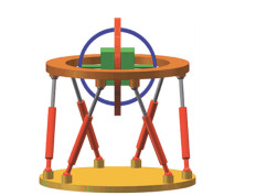
1 Introduction of the Model 1.1 Model of the Motion SimulatorThe model of the new flight simulator is shown in Fig. 1.
|
Fig.1 Model of the new flight simulator |
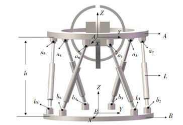
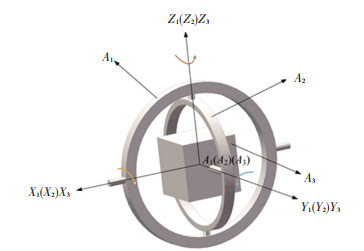
As shown in the Fig. 2 and Fig. 3, the upper body of the flight simulator is expressed as A and the lower part of the flight simulator is expressed as B. Three axis turntables are represented as Ai (i =1, 2, 3), which also represents the outer-loop, the middle-loop, and the inner-loop connected by revolute joints, and its axis is perpendicular to each other.
|
Fig.2 Coordinate system diagram of flight simulator |
|
Fig.3 Three-axis turntable diagram of flight simulator |
The coordinate systems are established, as shown in Fig. 3. Fixed with reference system B-XYZ, the original point B is located on the mass center of the base-platform. The original point A of system A-XYZ is located on mass center in the up-platform. Reference system Ai-XiYiZi (i=1, 2, 3) connects with the outer-loop, the middle-loop, and the inner-loop (working cabin) of the three-axis turntable, respectively.
1.2 Motion Parameter SettingThe upper-platform makes the general motion which comprises translational and rotational motions in the fixed reference system B-XYZ. The generalized coordinates q1, q2, q3 represent translation of the mass center A along BX, BY, BZ axes in the position of the static coordinate system B-XYZ, and generalized coordinates q4, q5, q6 denote the turning angle of upper-platform A around its body axis X, Y, Z, respectively. The rotation angle of each ring rotates around its body axis q7, q8, q9, respectively. At the initial moment, q7=0, q8=0, q9=0.
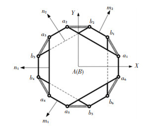
2 Kinematic Analysis of Motion Simulator 2.1 Location AnalysisLocation analysis is the most basic of kinematic analysis. The flight simulator is simplified as shown in Fig. 4. The long side length of the upper platform structure is n1, the short side length is m1, and the vertical distance between the upper platform and the lower platform is h.
|
Fig.4 Simplified structure diagram |
Similarly, suppose the length of the long side of the base platform is n2, the length of the short side is m2.
Then the initial position coordinate matrix of each hinge point in the coordinate system B-XYZ is as follows:
| $ [\boldsymbol{A}]=\left[\begin{array}{ccc} \frac{\sqrt{3}}{6}\left(2 n_{1}+m_{1}\right) & \frac{\sqrt{3}}{6}\left(m_{1}-n_{1}\right) & -\frac{\sqrt{3}}{6}\left(n_{1}+2 m_{1}\right) &-\frac{\sqrt{3}}{6}\left(n_{1}+2 m_{1}\right) & \frac{\sqrt{3}}{6}\left(m_{1}-n_{1}\right) & \frac{\sqrt{3}}{6}\left(2 n_{1}+m_{1}\right)\\ \frac{1}{2} m_{1} & \frac{1}{2}\left(m_{1}+n_{1}\right) & \frac{1}{2} n_{1}& -\frac{1}{2} n_{1} & -\frac{1}{2}\left(m_{1}+n_{1}\right) & -\frac{1}{2} m_{1}\\ h & h & h&h & h & h \end{array}\right] $ | (1) |
| $ [\boldsymbol{B}]=\left[\begin{array}{ccc} \frac{\sqrt{3}}{6}\left(n_{2}+2 m_{2}\right) & \frac{\sqrt{3}}{6}\left(n_{2}-m_{2}\right) & -\frac{\sqrt{3}}{6}\left(2 n_{2}+m_{2}\right) &-\frac{\sqrt{3}}{6}\left(2 n_{2}+m_{2}\right) & \frac{\sqrt{3}}{6}\left(n_{2}-m_{2}\right) & \frac{\sqrt{3}}{6}\left(n_{2}+2 m_{2}\right)\\ \frac{1}{2} m_{2} & \frac{1}{2}\left(m_{2}+n_{2}\right) & \frac{1}{2} m_{2}& -\frac{1}{2} m_{2} & -\frac{1}{2}\left(m_{2}+n_{2}\right) & -\frac{1}{2} n_{2} \\ 0 & 0 & 0&0 & 0 & 0 \end{array}\right] $ | (2) |
Then, the body coordinates of each hinge point on the platform can be converted to a fixed coordinate system through the coordinate transformation matrix.
| $ {\left[\boldsymbol{A}^{1}\right]=} {\left[\boldsymbol{T}_{3}\right]\left[\boldsymbol{T}_{4}\right]\left[\boldsymbol{T}_{5}\right][\boldsymbol{A}] } $ | (3) |
| $ {\left[\boldsymbol{B}^{1}\right]=[\boldsymbol{B}] } $ | (4) |
The above matrices [A1] and [B1] are the coordinate matrices of the platform hinge points in the B system after the direction cosine matrix transformation. [T3], [T4], [T5] matrix is the direction cosine matrix of the upper platform rotating around the AX, AY, AZ axis.
| $ \left[\boldsymbol{T}_{4}\right]=\left[\begin{array}{ccc} 1 & 0 & 0 \\ 0 & \cos q_{4} & \sin q_{4} \\ 0 & -\sin q_{4} & \cos q_{4} \end{array}\right] $ | (5) |
| $ \left[\boldsymbol{T}_{5}\right]=\left[\begin{array}{ccc} \cos q_{5} & 0 & -\sin q_{5} \\ 0 & 1 & 0 \\ \sin q_{5} & 0 & \cos q_{5} \end{array}\right] $ | (6) |
| $ \left[\boldsymbol{T}_{6}\right]=\left[\begin{array}{ccc} \cos q_{6} & \sin q_{6} & 0 \\ -\sin q_{6} & \cos q_{6} & 0 \\ 0 & 0 & 1 \end{array}\right] $ | (7) |
Therefore, the length of the real-time change of the driving branch is
| $ L_{i}=\sqrt{\sum\limits_{j=1}^{3}\left(a_{i j}-b_{i j}\right)^{2}}(i=1,2, \cdots, 6 ; j=1,2,3) $ | (8) |
In Eq.(8), aij and bij are the elements in the i-th column and j-th row of matrix [A1] and [B1], respectively.
2.2 Kinematics Analysis on Up PlatformIn the fixed coordinate system, the velocity of the center of mass of the upper-platform A is
| $ \boldsymbol{v}=\left[\begin{array}{lll} \dot{q}_{1} & \dot{q}_{2} & \dot{q}_{3} \end{array}\right]^{\mathrm{T}} $ | (9) |
where
| $ \boldsymbol{a}=\left[\begin{array}{lll} \ddot{q}_{1} & \ddot{q}_{2} & \ddot{q}_{3} \end{array}\right]^{\mathrm{T}} $ | (10) |
where
Suppose matrix[ABL is the directional cosine matrix from system A-XYZ to fixed system B-XYZ, and its expression is
| $ \begin{aligned} {\left[{ }_{A}^{B} \boldsymbol{L}\right]=} & {\left[\begin{array}{ccc} 1 & 0 & 0 \\ 0 & \cos q_{4} & -\sin q_{4} \\ 0 & \sin q_{4} & \cos q_{4} \end{array}\right]\left[\begin{array}{ccc} \cos q_{5} & 0 & -\sin q_{5} \\ 0 & 1 & 0 \\ \sin q_{5} & 0 & \cos q_{5} \end{array}\right] . } \\ & {\left[\begin{array}{ccc} \cos q_{6} & \sin q_{6} & 0 \\ -\sin q_{6} & \cos q_{6} & 0 \\ 0 & 0 & 1 \end{array}\right] } \end{aligned} $ | (11) |
According to formula
| $ \begin{aligned} \boldsymbol{\omega}=&\left[\begin{array}{ccc} \cos q_{6} \cos q_{5} & -\sin q_{5} & 0 \\ \sin q_{6} \cos q_{5} & \cos q_{6} & 0 \\ -\sin q_{5} & 0 & 1 \end{array}\right]\left[\begin{array}{l} \dot{q}_{4} \\ \dot{q}_{5} \\ \dot{q}_{6} \end{array}\right]= \\ &{\left[\begin{array}{c} \dot{q}_{4} \cos q_{6} \cos q_{5}-\dot{q}_{5} \sin q_{5} \\ \dot{q}_{4} \sin q_{6} \cos q_{5}+\dot{q}_{5} \cos q_{6} \\ \dot{q}_{6}-\dot{q}_{4} \sin q_{5} \end{array}\right]} \end{aligned} $ | (12) |
From the derivation of the above Eq.(12) with respect to time, the angular acceleration of the origin is obtained.
| $ \boldsymbol{\varepsilon}=\left[\begin{array}{c} \ddot{q}_{5} \cos q_{4}-\dot{q}_{5} \dot{q}_{4} \sin q_{4}+\ddot{q}_{6} \sin q_{4} \sin q_{5}+\dot{q}_{6} \dot{q}_{4} \cos q_{4} \sin q_{5}+\dot{q}_{6} \dot{q}_{5} \sin q_{4} \cos q_{5} \\ \ddot{q}_{5} \sin q_{4}-\dot{q}_{5} \dot{q}_{4} \cos q_{4}-\ddot{q}_{6} \cos q_{4} \sin q_{5}+\dot{q}_{6} \dot{q}_{4} \sin q_{4} \sin q_{5}+\dot{q}_{6} \dot{q}_{5} \cos q_{4} \sin q_{5} \\ \ddot{q}_{6} \cos q_{5}-\dot{q}_{6} \dot{q}_{5} \sin q_{5} \end{array}\right] $ | (13) |
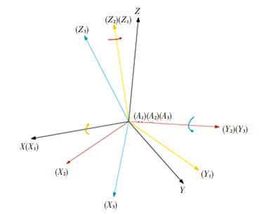
As shown in Fig. 5, it is the rotation form of the three-axis turntable.
|
Fig.5 The rotation form of the three-axis turntable |
The outer-loop, the middle-loop, and the inner-loop of the three-axis turntable make the fixed-point rotation around the mass center relative to upper-platform B. Three rigid body rotation angular velocity array at a fixed conference system B-XYZ can be expressed.
Angular velocity of the outer-loop is
| $ \boldsymbol{\omega}_{1}=\left[\boldsymbol{L}_{7}\right]^{\mathrm{T}}\left[\begin{array}{lll} \dot{q}_{7} & 0 & 0 \end{array}\right]^{\mathrm{T}}+\boldsymbol{\omega} $ | (14) |
Angular velocity of the middle-loop is
| $ \boldsymbol{\omega}_{2}=\left[\boldsymbol{L}_{8}\right]^{\mathrm{T}}\left[\begin{array}{lll} 0 & \dot{q}_{8} & 0 \end{array}\right]^{\mathrm{T}}+\boldsymbol{\omega}_{1} $ | (15) |
Angular velocity of theinner-loop is
| $ \boldsymbol{\omega}_{3}=\left[\boldsymbol{L}_{9}\right]^{\mathrm{T}}\left[\begin{array}{lll} 0 & 0 & \dot{q}_{9} \end{array}\right]^{\mathrm{T}}+\boldsymbol{\omega}_{2} $ | (16) |
where [L7, [L8, [L9 represent the direction of cosine matrix, which produces through the three-axis turntable rotation around the mass center of the upper-platform.
| $ {\left[\boldsymbol{L}_{7}\right]=\left[\begin{array}{ccc} 1 & 0 & 0 \\ 0 & \cos q_{7} & \sin q_{7} \\ 0 & -\sin q_{7} & \cos q_{7} \end{array}\right]} $ | (17) |
| $ {\left[\boldsymbol{L}_{8}\right]=\left[\begin{array}{ccc} \cos q_{8} & 0 & -\sin q_{8} \\ 0 & 1 & 0 \\ \sin q_{8} & 0 & \cos q_{8} \end{array}\right]} $ | (18) |
| $ {\left[\boldsymbol{L}_{9}\right]=\left[\begin{array}{ccc} \cos q_{9} & \sin q_{9} & 0 \\ -\sin q_{9} & \cos q_{9} & 0 \\ 0 & 0 & 1 \end{array}\right]} $ | (19) |
Change of ω1, ω2, ω3 with respect to time can be obtained corresponding angular acceleration array which is represented by α1, α2, α3.
It is worth mentioning that the three-axis turntable is mainly used to simulate the complex rotation of the aircraft in the air. This kind of rotation is not stable and has low-speed rotation, so it will not produce gyro effect.
3 Dynamic Analysis of the SimulatorThis article uses Newton-Euler method to model the dynamics of the flight simulator.
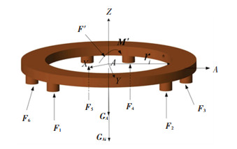
As shown in Fig. 6, the gravity GA, GAi of up platform, three-axis turntable, and driving force Fi by six drive rods are taken into consideration. F′ and M′ are the inertial force and moment of inertia of the system, respectively. ri is the position vector from the hinge point to the origin A. With all the force to the mass center A simplified, the main vector, and the main moment can be obtained.
|
Fig.6 The force analysis |
Suppose the unit vector matrix of the driving force of the 6 driving branches is S.
| $ \boldsymbol{S}=\left[\boldsymbol{s}_{i}\right], \boldsymbol{s}_{i}=\frac{a_{i}-b_{i}}{L_{i}}(i=1, \cdots, 6) $ | (20) |
Then the main vector of the platform can be written as fellows:
| $ \boldsymbol{F}=\sum\limits_{i=0}^{3} \boldsymbol{G}_{A i}+[\boldsymbol{S}]_{3 \times 6}\left[\boldsymbol{F}_{i}\right]_{6 \times 1} $ | (21) |
According to the Newton-Euler method, the inertia force of the platform is
| $ \boldsymbol{F}^{\prime}=\left(m_{0}^{\prime}+m_{1}^{\prime}+m_{2}^{\prime}+m_{3}^{\prime}\right) \cdot \boldsymbol{a} $ | (22) |
In the above formula, m0′ is the mass of the platform; m1′, m2′, m3′ are the masses of the three-axis turntable, respectively.
The main moment can be obtained as
| $ \boldsymbol{M}=\sum\limits_{i=1}^{6} \boldsymbol{r}_{i} \times \boldsymbol{F}_{i}=[\boldsymbol{R}][\boldsymbol{F}]_{6 \times 1} $ | (23) |
According to the Newton-Euler method, the moment of inertia of the platform is
| $ \boldsymbol{M}^{\prime}=\boldsymbol{J} \boldsymbol{\varepsilon}+\boldsymbol{\omega} \times(\boldsymbol{J} \boldsymbol{\omega}) $ | (24) |
In the above formula, J is the inertia tensor.
From Eqs.(21), (22), (23), and (24), the driving forces F1 to F6 and driving moments M1, M2, M3 can be obtained as follows:
| $ [\boldsymbol{F}]_{6 \times 1}=\left[\begin{array}{l} {[\boldsymbol{S}]} \\ {[\boldsymbol{R}]} \end{array}\right]^{-1}\left[\begin{array}{c} \boldsymbol{F}^{\prime}-\sum\limits_{i=0}^{3} \boldsymbol{G}_{\boldsymbol{A} i} \\ \boldsymbol{M}-\boldsymbol{M}^{\prime} \end{array}\right] $ | (25) |
Similarly, the dynamic analysis of the three-axis turntable is easy to get through the Newton-Euler equation:
| $ \begin{aligned} \boldsymbol{J}_{i} \boldsymbol{\alpha}_{i} &+\boldsymbol{\omega}_{i} \times \boldsymbol{J}_{i} \boldsymbol{\omega}_{i}=\left[\boldsymbol{L}_{4}\right]^{\mathrm{T}}\ \left[\boldsymbol{L}_{5}\right]^{\mathrm{T}}\ \left[\boldsymbol{L}_{6}\right]^{\mathrm{T}} \cdots \\ & {\left[\boldsymbol{L}_{i+6}\right]^{\mathrm{T}}\ \left[\boldsymbol{M}_{i}\right] \quad(i=0,1,2,3) } \end{aligned} $ | (26) |
where Ji is the inertia tensor of each rotating ring of the three-axis turntable. Mi is the rotational torque
| $ \begin{aligned} \boldsymbol{M}_{i}=&\left(\left[\boldsymbol{L}_{4}\right]^{\mathrm{T}}\left[\boldsymbol{L}_{5}\right]^{\mathrm{T}}\left[\boldsymbol{L}_{6}\right]^{\mathrm{T}} \ldots\left[\boldsymbol{L}_{i+6}\right]^{\mathrm{T}}\right)^{-1} \boldsymbol{J}_{i} \boldsymbol{\alpha}_{i}+\\ &\boldsymbol{\omega}_{i} \times \boldsymbol{J}_{i} \boldsymbol{\omega}_{i} (i=0,1,2,3) \end{aligned} $ | (27) |
Simulink is one of the most famous dynamic system simulation platforms in the world. In this study, simulation analysis of flight simulator is based on Simscape module in Simulink. Table 1 shows parameters of the flight simulator.
| Table 1 Actual parameter values of flight simulator |
Now, consider the complex trajectory of working cabin.
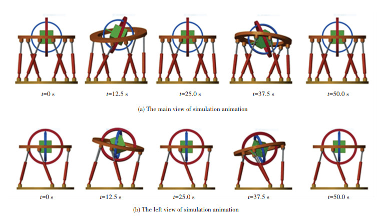
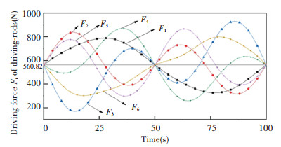
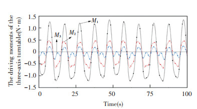
Set the motion equation of the flight simulator as q1=80sin(πt/25)mm, q2=40sin(πt/25)mm, q3=60sin(πt/25)mm, q4=0.1sin(πt/25)rad/s, q5=0.2sin(πt/25)rad/s, q6=0sin(πt/25)rad/s, q7=0.5sin(πt/2)rad/s, q8=0.5sin(πt/2) rad/s, and q9=0.3sin(πt/2) rad/s. Then the simulation animation is shown in Fig. 7, the driving force of the driving branch is shown in Fig. 8, and the driving torque of the three-axis turntable is shown in Fig. 9.
|
Fig.7 The diagram of simulation animation |
|
Fig.8 The driving forces of the drive rods |
|
Fig.9 The driving moments of the three-axis turntable |
From Fig. 7, you can see the motion form of the flight simulator, which has the characteristics of multiple degrees of freedom, large displacement, and 360-degree rotating space.
As shown in Fig. 8, F1, F2, F3, F4, F5, F6 denote the driving forces of six legs. The maximum driving force F4 is up to 886.530 N. The minimum driving force F3 is up to 162.730 N.
In Fig. 9, the driving moments of outer loop, middle loop, and inner loop are irregular. Outer loop's driving moment is bigger than those of the middle and inner loops.
In order to overcome the shortcoming of traditional parallel platform, a novel platform is proposed for flight simulator, which is composed of standard platform and three-axis turntable. Compared with traditional parallel platform, this nine-degree-of-freedom platform is capable of 360 degrees tilting motion and translation. Standard parallel platform has six degrees of freedom and three-axis turntable has three degrees of freedom. But during the simulation of six degree of freedom, standard parallel platform usually provides three translational motions for working cabin, and three rotational motions are provided by three-axis turntable. So, the platform's translations and rotations are decoupled, which makes kinematic analysis much easier.
Due to the character of three-axis turntable, 360 degrees overturn can be easily achieved. So, the novel platform overcomes the weakness of traditional parallel platform, whose rotation angle is limited to ±20-30 degrees. This research provides theoretical support for the feasibility of 360 degrees spinning flight simulator.
5 ConclusionsThis paper proposes a new type of flight simulator and introduces the model, which is based on the inverse kinematics method and Newton-Euler method. The theoretical analysis of the kinematics and dynamics of the simulator and the simulation analysis based on the Simulink platform were performed. Theoretical and simulation results show that the flight simulator can achieve six-degree-of-freedom motion, meanwhile the cabin can achieve 360-degree rotation in space, which restores the complex motion of the aircraft flying in the air to a greater extent. The flight simulator is helpful for pilots to obtain better training in the laboratory, and the research results in this paper also have certain reference value for the design and analysis of flight simulators.
| [1] |
Stewart D. A platform with six degree of freedom. Proceedings of the Institute of Mechanical Engineering, 1965, 180: 371-386. DOI:10.1243/PIME_PROC_1965_180_029_02 (  0) 0) |
| [2] |
Wu P D, Xiong H G, Kong J Y. Dynamic analysis of 6-SPS parallel mechanism. International Journal of Mechanics and Materials in Design, 2012, 8: 121-128. DOI:10.1007/s10999-012-9181-y (  0) 0) |
| [3] |
Mueller R A. Optimizing the performance of pilot control loaders at NASA vertical motion simulator. Journal of Aircraft, 2010, 47(2): 682-693. DOI:10.2514/1.45073 (  0) 0) |
| [4] |
Liu X, Zhao T S, Luo E J, et al. Coupling 3-PSR/PSU 5-axis compensation mechanism for stabilized platform and its analysis. Proceedings of the Institution of Mechanical Engineers, Part C: Journal of Mechanical Engineering Science, 2013, 227(1): 1619-1629. DOI:10.1177/0954406212460453 (  0) 0) |
| [5] |
Sun S H, Li H, Jia Y M, et al. Development of a simulation platform for spacecraft omni-directional rendezvous. Proceedings of 2016 Chinese Intelligent Systems Conference. Singapore: Springer-Verlag Singapore Pte Ltd., 2016, 77-88. (  0) 0) |
| [6] |
Park M C, Kang M K, Kang H M, et al. Implementation of flight simulator using 6DOF motion platform. Journal of the Korean Society of Computer Information Conference, 2018, 23(8): 17-23. DOI: 10.9708.jksci.2018.23.08.017.
(  0) 0) |
| [7] |
Shao Z F, Tang X Q, Chen X, et al. Driving force analysis for the secondary adjustable system in FAST. Robotica, 2011, 29(6): 903-915. DOI:10.1017/s0263574711000117 (  0) 0) |
| [8] |
Wang W L, Cao H J. Flexible parallel robot and its experiment models used in FAST. Applied Mechanics and Materials, 2013, 401-403: 159-162. DOI:10.4028/www.scientific.net/AMM.401-403.159 (  0) 0) |
| [9] |
Kim J W, Hwang J C, Kim J S, et al. Eclipse Ⅱ: a new parallel mechanism enabling continuous 360-degree spinning plus three-axis translational motions. IEEE Transactions on Robotics and Automation, 2002, 18(3): 367-373. DOI:10.1109/TRA.2002.1019472 (  0) 0) |
| [10] |
Jiang S T. Research on General Aviation Flight Simulation Motion Control System. Shijiazhuang: Hebei University of Science and Technology, 2019, 15-16. (  0) 0) |
| [11] |
Zhang B F. Research and Optimization on the New Structure of Six DOF Motion Platform Washout Algorithm. Tianjin: Civil Aviation University of China, 2019: 53-58.
(  0) 0) |
| [12] |
Du H H. Design of six-DOF attitude simulation system for flight simulator. Journal of Civil Aviation University of China, 2020, 38(4): 27-30. (  0) 0) |
| [13] |
Mcclintic and Frank. Flight simulator. USA, 2005.
(  0) 0) |
| [14] |
Kim J, Park F C, Ryu S J, et al. Design and analysis of a redundantly actuated parallel mechanism for rapid machining. IEEE Transactions on Robotics and Automation, 2001, 17(4): 423-434. DOI:10.1109/70.954755 (  0) 0) |
| [15] |
Chen H. Design and Kinematic Analysis for a Novel Flight Simulator. Beijing: Beijing Jiaotong University, 2014: 49-53.
(  0) 0) |
| [16] |
Zhou Y, Ji X, Li H, et al. Structural design and the state of motion analyzes for multi-degree-of freedom electro-hydraulic mix-drive motion simulator. Key Engineering Materials, 2009, 419-420: 169-172. DOI:10.4028/www.scientific.net/KEM.419-420.169 (  0) 0) |
| [17] |
Liu Y Z, Hong J Z, Yang H X. Multibody System Dynamics. Beijing: Higher Education Press, 2014: 2-185.
(  0) 0) |
 2022, Vol. 29


