With the increasingly fierce competition in space technology around the world, the FFSRs are playing an increasingly important role in the field of on-orbit service (OOS), such as transporting payloads, recovering and releasing satellites, maintaining orbit spacecraft and capturing space debris[1-3]. Because the FFSR is in the condition of momentum conservation, its dynamics and kinematics are strongly coupled, which makes the motion path planning of FFSR more complicated[4-5]. In other words, the FFSR system obeys the law of conservation of momentum in space environment, so the motion of the manipulator will cause a large attitude disturbance to the satellite[6-7]. The disturbance of the satellite attitude will have an effect on such tasks as the communications and the earth-observation[8-9]. Meanwhile, it will also bring a huge challenge to the attitude control system. Therefore, it is of great significance to study the path planning of the FFSR with minimal attitude disturbance to the satellite in order to complete the service task of OOS.
A variety of optimization methods and path planning strategies have been developed for the path planning problem of the FFSR. Rybus[10] presented a path planning scheme based on bidirectional rapidly-exploring random trees (RRT) algorithm, and the purpose is to make the desired change of satellite attitude. Okubo et al.[11] designed a path planning method using enhanced disturbance map (EDM) method that reduces attitude disturbance of the base satellite. Flores-Abad et al.[12-13] worked on path planning of the FFSR to capture a space non-cooperative rolling target. Wang et al.[14] investigated the path planning of the kinematically redundant FFSR based on the Partible Swarm Optimization (PSO) strategy.
The path planning problem of the FFSR is usually described as the optimal control problem (OCP), and the methods of solving OCP are generally classified into two kinds: the indirect method and the direct method[15]. In the indirect method, the OCP is transformed into the Hamilton boundary value problem, and then the Hamilton boundary value problem is solved by the maximum principle. The indirect method has the advantage of solving the optimization problem with high accuracy, but it has small convergence domain and complicated solution process, and it is inefficient to solve the OCP with path constraints. In contrast, the direct method has the advantages of wide convergence domain and low initial value estimation. It does not need to guess the values of the initial covariant variables accurately, uses the discretization method to transform the OCP into the NLP, and then optimizes the performance index by the numerical method. The Gauss pseudospectral method (GPM) is the most well-developed pseudospectral methods in solving NLP problems. As a branch of direct method, the GPM develops extremely rapidly in recent years, and applies widely in complex OCP, such as aircraft trajectory optimization[15], launch vehicle trajectory optimization[16-17], spacecraft formation reconfiguration[18] and space robot path planning[19].
Compared with the traditional direct method, the GPM has the characteristics of fast convergence. However, when the OCP is non-smooth, the p-method has a slow convergence rate, and even cannot solve the OCP which requires high accuracy. The h-method may require using a large number of segments to achieve an acceptable error tolerance. Therefore, Darby et al.[20-21] proposed an hp-AGPM to get the solution of the OCP. In this method, a two-tiered strategy is used to determine the number of segments and the order of the polynomial, and the purpose is to achieve a specified solution accuracy in each segment.
This paper focus on the path planning of the FFSR with minimum attitude disturbance of the satellite by using the hp-AGPM and analyses the convergence of the proposed method. The remainder of this paper is organized as follows. In Section 1, the general kinematics and dynamics models of the FFSR are outlined. Then the path planning problem of the minimum reaction torque of the satellite is established in the form of OCP. In Section 2, the theories and associated equations in the hp-AGPM are introduced. In Section 3, the convergence analysis of hp-AGPM is provided. In Section 4, the numerical simulations of a simplified planar 2-DOF FFSR are shown to validate the effectiveness of the proposed method. Conclusions are drawn in Section 5.
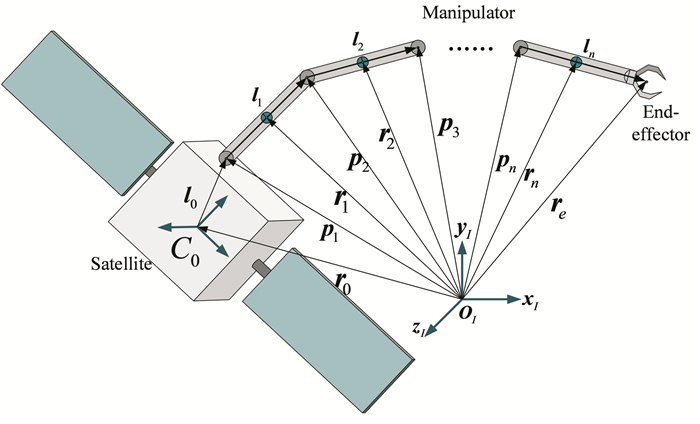
1 Path Planning Model 1.1 Kinematics and Dynamics ModelThis paper makes the following assumptions about the FFSR system: 1) the FFSR system consists of a rigid satellite and n rigid manipulator links; 2) each joint has only one rotational degree-of-freedom; 3) in the process of the capture maneuver, the attitude and position of the satellite is not controlled.
The kinematics and the dynamics models of the FFSR system are established in the inertial reference coordinate system oxIyIzI, as shown in Fig. 1.The position vector of the manipulator's end-effector is described as
| $ \boldsymbol{r}_{e}=\boldsymbol{r}_{0}+\sum\limits_{i=0}^{n} \boldsymbol{l}_{i} $ | (1) |
|
Fig.1 Configuration of the FFSR |
where re and r0 are the position vector of the end-effector and the centroid of satellite, respectively; l0 and li(i=1, 2, …, n) are the position vector of the first joint with respect to the centroid of satellite and the link i, respectively.
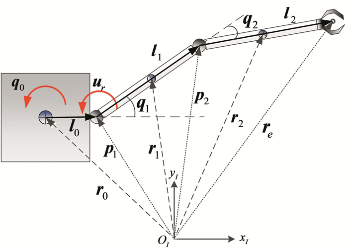
For ease of illustration, the planar 2-DOF FFSR model is used to verify the design method, which is described in Fig. 2. Define re=[xe, ye]T and r0=[x0, y0]T, the kinematics equations of the 2-DOF FFSR are as follows:
| $ \left\{\begin{array}{c} x_{e}=x_{0}+\left\|\boldsymbol{l}_{0}\right\| \cos \left(q_{0}\right)+\left\|\boldsymbol{l}_{1}\right\| \cos \left(q_{0}+q_{1}\right)+ \\ \left\|\boldsymbol{l}_{2}\right\| \cos \left(q_{0}+q_{1}+q_{2}\right) \\ y_{e}=y_{0}+\left\|\boldsymbol{l}_{0}\right\| \sin \left(q_{0}\right)+\left\|\boldsymbol{l}_{1}\right\| \sin \left(q_{0}+q_{1}\right)+ \\ \left\|\boldsymbol{l}_{2}\right\| \sin \left(q_{0}+q_{1}+q_{2}\right) \end{array}\right. $ | (2) |
|
Fig.2 Configuration of the 2-DOF FFSR |
where q0 is the angle of satellite and qi(i=1, 2) is the joint angle of joint i.
The linear velocity vector of the end-effector in oxIyIzI is obtained by the derivative of time of Eq.(2).
| $ \boldsymbol{v}_{e}=\boldsymbol{v}_{0}+\left[\begin{array}{l} -\omega_{0}\left\|l_{0}\right\| \sin \left(q_{0}\right)-\left\|l_{1}\right\| \sin \left(q_{0}+q_{1}\right) \sum\limits_{i=0}^{1} \dot{q}_{i}-\left\|l_{2}\right\| \sin \left(q_{0}+q_{1}+q_{2}\right) \sum\limits_{i=0}^{2} \dot{q}_{i} \\ \omega_{0}\left\|l_{0}\right\| \cos \left(q_{0}\right)+\left\|l_{1}\right\| \cos \left(q_{0}+q_{1}\right) \sum\limits_{i=0}^{1} \dot{q}_{i}+\left\|l_{2}\right\| \cos \left(q_{0}+q_{1}+q_{2}\right) \sum\limits_{i=0}^{2} \dot{q}_{i} \end{array}\right] $ | (3) |
where ve and
In deep space environment, the gravity and other external forces have little influence on the FFSR, so they are neglected in the process of analysis. Therefore, the momentum of the FFSR system are conserved. Suppose the generalized coordinate q=[q0, q1, q2]T. The dynamics equation of the FFSR system is derived as follows according to the Lagrange equation:
| $ \boldsymbol{M}(\boldsymbol{q}) \ddot{\boldsymbol{q}}+\boldsymbol{C}(\boldsymbol{q}, \dot{\boldsymbol{q}}) \dot{\boldsymbol{q}}=\boldsymbol{u} $ | (4) |
where M(q) is the generalized inertial tensor matrix,
In this paper, the purpose of path planning of the end-effector is to obtain a special trajectory from a given initial position to the target capturing position, and minimize reaction torque of the satellite at the same time. Furthermore, the total reaction torque ur caused by the manipulator motion at the satellite is defined as
| $ \boldsymbol{u}_{r}=-\sum\limits_{i=1}^{n}\left(\boldsymbol{I}_{i} \ddot{\boldsymbol{q}}_{i}+\left(\boldsymbol{r}_{i}-\boldsymbol{l}_{0}\right) \times m_{i} \dot{\boldsymbol{v}}_{i}\right) $ | (5) |
where mi and vi are the mass and the translational velocity of link i, respectively.
To find the set of optimal control torques, the objective function of OCP is chosen as
| $ J=\int_{t_{0}}^{t_{\mathrm{f}}} \boldsymbol{u}_{r}^{\mathrm{T}} \boldsymbol{u}_{r} \mathrm{d} t=\int_{t_{0}}^{t_{\mathrm{f}}} \boldsymbol{g}(\boldsymbol{x}(t), \boldsymbol{u}(t)) \mathrm{d} t $ | (6) |
where t0 and tf are the initial and the final moment of the manipulator motion, respectively.
Selecting the state variable
| $ \dot{\boldsymbol{x}}=\boldsymbol{L}(\boldsymbol{x})+\boldsymbol{G}(\boldsymbol{x}) \boldsymbol{u}=f(\boldsymbol{x}(t), \boldsymbol{u}(t)) $ | (7) |
where
| $ \boldsymbol{L}(\boldsymbol{x})=\left[\begin{array}{cc} 0 & 1 \\ 0 & -\boldsymbol{M}(\boldsymbol{x})^{-1} \boldsymbol{C}(\boldsymbol{x}) \end{array}\right] \boldsymbol{x} $ |
| $ \boldsymbol{G}(\boldsymbol{x})=\left[\begin{array}{c} 0 \\ \boldsymbol{M}(\boldsymbol{x})^{-1} \end{array}\right] $ |
The OCP of manipulator motion can be described as
| $ \operatorname{minimize} \quad J=\int_{t_{0}}^{t_{\mathrm{f}}} \boldsymbol{g}(\boldsymbol{x}(t), \boldsymbol{u}(t)) \mathrm{d} t $ | (8) |
Subject to
| $ \dot{\boldsymbol{x}}=\boldsymbol{f}(\boldsymbol{x}(t), \boldsymbol{u}(t)) $ |
| $ \boldsymbol{x}\left(t_{0}\right)=\boldsymbol{x}_{0}=\left[\boldsymbol{q}_{0}^{\mathrm{T}}, \dot{\boldsymbol{q}}_{0}{}^{\mathrm{T}}\right]^{\mathrm{T}} $ |
| $ \boldsymbol{x}_{\min } \leqslant \boldsymbol{x}(t) \leqslant \boldsymbol{x}_{\max } $ |
| $ \boldsymbol{u}_{\min } \leqslant \boldsymbol{u}(t) \leqslant \boldsymbol{u}_{\max } $ |
where q0 and qf are the vectors of joint angles in the initial and final moment, respectively; xmin and xmax are the lower boundary and the upper boundary of the state variable, respectively; umin and umax are the lower boundary and the upper boundary of the control variable, respectively.
The time interval of Bolza OCP is τ∈[-1, 1], so the time interval t∈[t0, tf] is necessary to be transformed to τ∈[-1, 1] via the below affine transformation.
| $ \tau=\frac{2 t}{t_{\mathrm{f}}-t_{0}}-\frac{t_{\mathrm{f}}+t_{0}}{t_{\mathrm{f}}-t_{0}} $ | (9) |
Then, the objective function described by Eq.(6) can be changed to
| $ J=\frac{t_{\mathrm{f}}-t_{0}}{2} \int_{-1}^{1} \boldsymbol{g}(\boldsymbol{x}(\boldsymbol{\tau}), \boldsymbol{u}(\boldsymbol{\tau})) \mathrm{d} \tau $ | (10) |
The dynamics equation Eq.(7) is given in terms of τ as follows:
| $ \frac{\mathrm{d} \boldsymbol{x}}{\mathrm{d} \tau}=\frac{t_{\mathrm{f}}-t_{0}}{2} \boldsymbol{f}(\boldsymbol{x}(\tau), \boldsymbol{u}(\tau)) $ | (11) |
T7he OCP is transformed to the following Bolza form:
| $ \operatorname{minimize} \quad J=\frac{t_{\mathrm{f}}-t_{0}}{2} \int_{-1}^{1} \boldsymbol{g}(\boldsymbol{x}(\tau), \boldsymbol{u}(\tau)) \mathrm{d} \tau $ | (12) |
Subject to
| $ \dot{x}=\frac{t_{\mathrm{f}}-t_{0}}{2} \boldsymbol{f}(\boldsymbol{x}({\tau}), \boldsymbol{u}({\tau})) $ |
| $ \boldsymbol{x}\left(\tau_{0}\right)=\boldsymbol{x}_{0}=\left[\boldsymbol{q}_{0}^{\mathrm{T}}, \dot{\boldsymbol{q}}_{0}{}^{\mathrm{T}}\right]^{\mathrm{T}} $ |
| $ \boldsymbol{x}_{\min } \leqslant \boldsymbol{x}({\tau}) \leqslant \boldsymbol{x}_{\max } $ |
| $ \boldsymbol{u}_{\min } \leqslant \boldsymbol{u}({\tau}) \leqslant \boldsymbol{u}_{\max } $ |
The GPM is a discretization method approximating the state and control trajectories using interpolating polynomials. There are (N+1) discrete points in the GPM which are composed of the initial point τ0=-1 and the N LG points, where the LG points are the zeroes of Nth-order Legendre polynomial. The state variables and control variables are approximated at the discrete points as
| $ \left\{\begin{array}{l} \boldsymbol{x}(\tau) \approx \boldsymbol{X}({\tau})=\sum\limits_{i=0}^{N} \boldsymbol{X}\left(\tau_{i}\right) \boldsymbol{L}_{i}({\tau}) \\ \boldsymbol{u}({\tau}) \approx \boldsymbol{U}({\tau})=\sum\limits_{i=1}^{N} \boldsymbol{U}\left(\tau_{i}\right) \boldsymbol{L}_{i}(\tau) \end{array}\right. $ | (13) |
where U(τ) and X(τ) are the mappings of the control variable u and the state variable x on the time interval τ∈[-1, 1], respectively; Li(τ) is a basis function of Lagrange polynomials and given by
| $ L_{i}(\tau)=\prod\limits_{j=0, j \neq i}^{N} \frac{\tau-\tau_{j}}{\tau_{i}-\tau_{j}}, i=0,1, \cdots, N $ | (14) |
Solving Eq.(11) by Gauss quadrature formula, there is
| $ \begin{gathered} \int_{x_{0}}^{x_{\mathrm{f}}} \mathrm{d} \boldsymbol{x}=\frac{t_{\mathrm{f}}-t_{0}}{2} \int_{-1}^{1} \boldsymbol{f}(\boldsymbol{x}(\tau), \boldsymbol{u}(\tau)) \mathrm{d} \tau \approx \\ \frac{t_{\mathrm{f}}-t_{0}}{2} \sum\limits_{i=1}^{N} \omega_{\mathrm{i}} \boldsymbol{f}\left(\boldsymbol{x}\left(\tau_{i}\right), \boldsymbol{u}\left(\tau_{i}\right)\right) \end{gathered} $ | (15) |
The terminal state of system is approximated by
| $ \boldsymbol{X}_{\mathrm{f}} \approx \boldsymbol{X}_{0}+\frac{t_{\mathrm{f}}-t_{0}}{2} \sum\limits_{i=1}^{N} \omega_{i} \boldsymbol{f}\left(\boldsymbol{x}\left(\tau_{i}\right), \boldsymbol{u}\left(\tau_{i}\right)\right) $ | (16) |
where ωi is the Gauss weights.
The path constraints at each discrete point is approximated by
| $ \left\{\begin{array}{l} \boldsymbol{x}_{\min } \leqslant \boldsymbol{X}\left(\tau_{i}\right) \leqslant \boldsymbol{x}_{\max }, i=1,2, \cdots, N \\ \boldsymbol{u}_{\min } \leqslant \boldsymbol{U}\left(\tau_{i}\right) \leqslant \boldsymbol{u}_{\max }, i=1,2, \cdots, N \end{array}\right. $ | (17) |
Then, Eq.(10) is approximated as the following function by using an LG quadrature.
| $ \begin{gathered} J=\frac{t_{\mathrm{f}}-t_{0}}{2} \int_{\tau_{0}}^{\tau_{\mathrm{f}}} \boldsymbol{g}(\boldsymbol{x}({\tau}), \boldsymbol{u}({\tau})) \mathrm{d} \tau \approx \\ \frac{t_{\mathrm{f}}-t_{0}}{2} \sum\limits_{i=1}^{N} \omega_{i} \boldsymbol{g}\left(\boldsymbol{x}\left(\tau_{i}\right), \boldsymbol{u}\left(\tau_{i}\right)\right) \end{gathered} $ | (18) |
In this way, the optimization problem of the minimum reaction torque of the base satellite is discretized into a NLP problem.
2.2 hp-AGPM MethodThe hp-AGPM is a method in which the segments number and the polynomial order in each segment are determined adaptively. It can provide accurate approximation for solving Bolza OCP.
It is assumed that t∈[t0, tf] of the manipulator motion is divided into S segments, and the corresponding time interval of segment s is [ts-1, ts], where s∈{1, …, S}, t0 < t1 < … < tS=tf.
In segment s, the time interval is transformed to the interval τ∈[-1, 1] by the following affine transformation:
| $ \tau=\frac{2 t}{t_{s}-t_{s-1}}-\frac{t_{s}+t_{s-1}}{t_{s}-t_{s-1}} $ | (19) |
Then, the OCP Eq.(12) is approximated to the following NLP function:
| $ \operatorname{minimize} \quad J=\frac{h}{2} \sum\limits_{i=1}^{N} \boldsymbol{\omega}_{i} \boldsymbol{U}_{r}^{(s) \mathrm{T}}\left({\tau}_{i}\right) \boldsymbol{U}_{r}^{(s)}\left({\tau}_{i}\right) $ | (20) |
Subject to
| $ \sum\limits_{i=0}^{N} D_{k, i} \boldsymbol{X}_{i}^{(s)}=\frac{h}{2} \boldsymbol{f}\left(\boldsymbol{X}_{k}^{(s)}, \boldsymbol{U}_{k}^{(s)}\right), 0 \leqslant k \leqslant N, 1 \leqslant s \leqslant S $ |
| $ \boldsymbol{X}_{1}^{(1)}=x_{0} $ |
| $ \boldsymbol{X}_{N+1}^{(s)}=\boldsymbol{X}_{1}^{(s+1)}, \ \ \ \ \ \ \ \ \ \ \ \ \ \ 1 \leqslant s \leqslant S-1 $ |
| $ \boldsymbol{x}_{\min } \leqslant \boldsymbol{X}_{k}^{(s)} \leqslant \boldsymbol{x}_{\max }, \ \ \ \ \ \ \ 0 \leqslant k \leqslant N, 1 \leqslant s \leqslant S $ |
| $ \boldsymbol{u}_{\min } \leqslant \boldsymbol{U}_{k}^{(s)} \leqslant \boldsymbol{u}_{\max }, \ \ \ \ \ \ \ 0 \leqslant k \leqslant N, 1 \leqslant s \leqslant S $ |
In segment s, the curvature of the mth component of the state variable is obtained as
| $ \kappa^{(s)}(\tau)=\frac{\left|X_{m}^{(\mathrm{s})}(\tau)\right|}{\left|\left[1+\dot{x}_{m}^{(s)}(\tau)^{2}\right]^{3 / 2}\right|} $ | (21) |
Let peak-to-average rate rs be the metric to determine whether to increase the collocation points in segment s or subdivide the segment s, and it is calculated as
| $ \boldsymbol{r}_{s}=\frac{\boldsymbol{\kappa}_{\max }^{(s)}}{\bar{\boldsymbol{\kappa}}^{(s)}} $ | (22) |
where κmax(s) is the maximum value of κ(s)(τ) and κ(s)is the mean value of κ(s)(τ).
Let
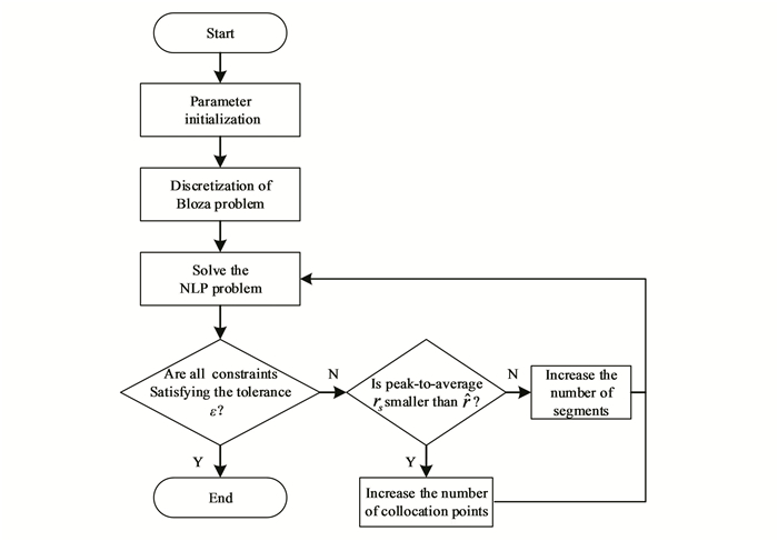
The iterative procedure of the hp-AGPM is as follows:
1) Initialize the parameters and choose M collocation points.
2) The Bolza OCP is discretized on the collocation points, then the OCP is converted to a discrete NLP problem.
3) Solve the discrete NLP problem.
4) Determine whether the constraints of boundary, path and dynamic in each segment are satisfied to the maximum allowable tolerance ε. For all constraints are out of the given tolerance, proceed to Step 5), or terminate the iteration.
5) Check for peak-to-average rate rs if it is smaller than the user-specified parameter
6) Increase the number of collocation points, i.e., increase the order of the Lagrange interpolation polynomial, then return to Step 3).
7) Divide the segment into multiple segments, then return to Step 3).
The iterative flow chart of the hp-AGPM is presented as follows.
|
Fig.3 The iterative flow chart of hp-AGPM |
3 Convergence Analysis for hp-AGPM
This section provides the proof of the convergence theorem for the designed hp-AGPM. To analyze the convergence of hp-AGPM, the following assumptions are employed:
Assumption 1: The continuous optimal problem Eq. (12) has a local optimal solution (x*, u*)∈Cl+1(Rn)×L∞(Rm) for l≥3. There is an open set Γ⊂Rn×Rm and ρ>0 satisfying the following function.
| $ \mathrm{B}_{\rho}\left(x^{*}(t), u^{*}(t)\right) \subset \varGamma \text { or all } t \in[-1,1] $ | (23) |
where Bρ(×) is the closed ball set whose radius is ρ and centers at ×, Ck is the collection of real-valued k times continuously differential functions on the interval [-1, +1], and L∞ denotes the space of essentially bounded functions.
Furthermore, there exits associated covariate λ*∈Cl+1(Rn) and μ*∈Rn, which satisfies the following equations (Pontryagin's minimum principle):
| $ \boldsymbol{\lambda}^{*}(-1)=\boldsymbol{\mu}^{*} $ | (24) |
| $ \dot{\boldsymbol{\lambda}}^{*}(t)=-\nabla_{x} \boldsymbol{H}\left(\boldsymbol{x}^{*}(t), \boldsymbol{u}^{*}(t), \boldsymbol{\lambda}^{*}(t)\right) $ | (25) |
| $ 0=\nabla_{u} \boldsymbol{H}\left(\boldsymbol{x}^{*}(t), \boldsymbol{u}^{*}(t), \boldsymbol{\lambda}^{*}(t)\right) $ | (26) |
where H is the Hamiltonian and its specific expression is
| $ \boldsymbol{H}\left(\boldsymbol{x}^{*}, \boldsymbol{u}^{*}, \boldsymbol{\lambda}^{*}\right)=\left\langle\boldsymbol{\lambda}^{*}, \boldsymbol{f}\left(\boldsymbol{x}^{*}, \boldsymbol{u}^{*}\right)\right\rangle $ | (27) |
where 〈ζ, ξ〉 is the inner product of ζ and ξ.
Assumption 2: For some α>0, the smallest eigenvalues of the following matrices are greater than or equal to α:
| $ \boldsymbol{V}=\nabla_{x x} \boldsymbol{J}\left(\boldsymbol{x}^{*}(t)\right) $ | (28) |
| $ {\left[\begin{array}{c} \boldsymbol{Q}(t) & \boldsymbol{S}(t) \\ \boldsymbol{S}(t) & \boldsymbol{R}(t) \end{array}\right] \text { for all } t \in[-1,1]} $ | (29) |
where
| $ \boldsymbol{Q}(t)=\nabla_{x x} \boldsymbol{H}\left(\boldsymbol{x}^{*}(t), \boldsymbol{u}^{*}(t), \boldsymbol{\lambda}^{*}(t)\right) $ |
| $ \boldsymbol{S}(t)=\nabla_{u x} \boldsymbol{H}\left(\boldsymbol{x}^{*}(t), \boldsymbol{u}^{*}(t), \boldsymbol{\lambda}^{*}(t)\right) $ |
| $ \boldsymbol{R}(t)=\nabla_{u u} \boldsymbol{H}\left(\boldsymbol{x}^{*}(t), \boldsymbol{u}^{*}(t), \boldsymbol{\lambda}^{*}(t)\right) $ |
Assumption 3: Assume
The vector sequences X*(s), U*(s) and λ*(s) are defined as
| $ \begin{gathered} \boldsymbol{X}_{i}^{*(s)}=\boldsymbol{x}^{*(s)}\left({\tau}_{i}\right), \boldsymbol{U}_{i}^{*(s)}=\boldsymbol{u}^{*(s)}\left({\tau}_{i}\right), \\ \boldsymbol{\lambda}_{i}^{*(s)}=\boldsymbol{\lambda}^{*(s)}\left({\tau}_{i}\right) \end{gathered} $ | (30) |
where 1≤i≤N.
If the following theorem is established, the method designed is convergent.
Theorem 1: If Assumptions 1-3 hold, the discrete problem Eq. (20) has an extreme point
| $ \begin{gathered} \max \limits_{1 \leqslant s \leqslant S}\left(\left\|\tilde{\boldsymbol{X}}^{(s)}-\boldsymbol{X}^{*(s)}\right\|_{\infty}+\left\|\tilde{\boldsymbol{U}}^{(s)}-\boldsymbol{U}^{*(s)}\right\|_{\infty}+\right. \\ \left.\left\|\tilde{\boldsymbol{\lambda}}^{(s)}-\boldsymbol{\lambda}^{*(s)}\right\|_{\infty}\right) \leqslant \frac{c h^{l}}{N^{l-\frac{5}{2}}} \end{gathered} $ | (31) |
where S is the number of segments, h is the length between adjacent collocation points, N is the number of collocation points on each segment, l is the continuous differentiable order of the state variable, and c is a constant.
Proof: Let χ be a Banach space and γ be a linear normed space. The norm in both spaces are described by ‖·‖. In order to prove Theorem 1, several lemmas presented in Ref. [23] are introduced first.
Lemma 1: If Assumptions 1-3 holds, for each ε>0, there is r>0 such that for all θ∈Br(θ*),
| $ \left\|\nabla T(\theta)-\nabla T\left(\theta^{*}\right)\right\| \leqslant \varepsilon $ | (32) |
where ‖·‖ is the matrix norm induced by the L∞ norm on χ and γ , and r is independent of N.
Lemma 2: If Assumptions 1-3 hold, ‖▽T(θ)-1‖ is bounded by a constant independent of N and K.
If Lemma 1 and Lemma 2 hold, the following proposition exists according Ref. [24]:
Proposition 1: Let Τ: χ → γ. T is continuously Fréchet differentiable in Br(θ*) for some θ*∈ χ and r>0. If εμ < 1, where μ=‖▽T(θ)-1‖ and ‖T(θ*)‖≤(1-με)r/μ, there is a unique θ∈Br(θ*) that makes T(θ)=0. Moreover, the following estimation inequality holds:
| $ \left\|\theta-\theta^{*}\right\| \leqslant \frac{\mu}{1-\mu \varepsilon}\left\|T\left(\theta^{*}\right)\right\| $ | (33) |
In this paper, let
| $ \tilde{\boldsymbol{X}} =\left(\tilde{\boldsymbol{X}}_{0}^{(s)}, \cdots, \tilde{\boldsymbol{X}}_{N}^{(s)}\right) $ |
| $ \tilde{\boldsymbol{U}} =\left(\tilde{\boldsymbol{U}}_{0}^{(s)}, \cdots, \tilde{\boldsymbol{U}}_{N}^{(s)}\right) $ |
| $ \tilde{\boldsymbol{\lambda}} =\left(\tilde{\boldsymbol{\lambda}}_{0}^{(s)}, \cdots, \tilde{\boldsymbol{\lambda}}_{N}^{(s)}\right) $ |
and 1≤s≤S. Let θ*=(X*, U*, λ*), where the tuples are similar to θ . The norm is the discrete L∞ given by
| $ \begin{aligned} &\|\boldsymbol{\theta}\|=\|(\boldsymbol{X}, \boldsymbol{U}, \boldsymbol{\lambda})\|_{\infty}= \\ &\quad \max \left\{\|\boldsymbol{X}\|_{\infty},\|\boldsymbol{U}\|_{\infty},\|\boldsymbol{\lambda}\|_{\infty}\right\} \end{aligned} $ | (34) |
The mapping T is given as follows:
| $ \boldsymbol{T}(\boldsymbol{X}, \boldsymbol{U}, \boldsymbol{\lambda})=\left\{\begin{array}{l} \sum\limits_{j=0}^{N} D_{k, j} \boldsymbol{X}_{j}^{(s)}-\frac{h}{2} f\left(\boldsymbol{X}_{k}^{(s)}, \boldsymbol{U}_{k}^{(s)}\right), 0 \leqslant k \leqslant N, 1 \leqslant s \leqslant S \\ \boldsymbol{X}_{0}^{(1)}-x_{0} \\ \boldsymbol{X}_{N}^{(s)}-\boldsymbol{X}_{0}^{(s+1)}, 1 \leqslant s \leqslant S-1 \\ \sum\limits_{j=0}^{N} D_{0, j}^{\dagger} \lambda_{j}^{(\mathrm{s})}+\frac{h}{2} \nabla_{X} \boldsymbol{H}\left(\boldsymbol{X}_{0}^{(S)}, \boldsymbol{U}_{0}^{(S)}, \boldsymbol{\lambda}_{0}^{(s)}\right)-\frac{1}{\omega_{1}}\left(\boldsymbol{\lambda}_{N}^{(s-1)}-\boldsymbol{\lambda}_{0}^{(s)}\right), 1 \leqslant s \leqslant S \\ \sum\limits_{j=1}^{N} D_{i, j}^{\dagger} \boldsymbol{\lambda}_{j}^{(s)}+\frac{h}{2} \nabla_{X} \boldsymbol{H}\left(\boldsymbol{X}_{i}^{(S)}, \boldsymbol{U}_{i}^{(S)}, \boldsymbol{\lambda}_{i}^{(S)}\right), 0 \leqslant i \leqslant N, 1 \leqslant s \leqslant S \\ \nabla_{U} \boldsymbol{H}\left(\boldsymbol{X}_{i}^{(s)}, \boldsymbol{U}_{i}^{(s)}, \boldsymbol{\lambda}_{i}^{(s)}\right), 0 \leqslant i \leqslant N, 1 \leqslant s \leqslant S \\ \boldsymbol{\lambda}_{N}^{(s)}-\boldsymbol{\lambda}_{N}^{(s-1)}+\frac{h}{2} \sum\limits_{i=1}^{N} \boldsymbol{\omega}_{i} \nabla_{X} \boldsymbol{H}\left(\boldsymbol{X}_{i}^{(s)}, \boldsymbol{U}_{i}^{(s)}, \boldsymbol{\lambda}_{i}^{(s)}\right), 1 \leqslant k \leqslant K \end{array}\right. $ | (35) |
where Di, j† is defined by
| $ D_{i, j}^{\dagger}=-\frac{\omega_{j}}{\omega_{i}} D_{i, j} $ |
Lemma 3: If Assumption 1 holds, there is a constant c independent of N and S. Thus
| $ \left\|T\left(\theta^{*}\right)\right\| \leqslant \frac{c h^{l+1}}{N^{l-\frac{5}{2}}} $ | (36) |
The proof of Lemma 3 is given in Ref.[23].
We combine Eq. (32) with Lemma 3 to obtain the estimate of Eq.(30) of Theorem 1. Theorem 1 shows that the discrete NLP has an extreme point and associated transformed adjoint variable which converge to the solution of the OCP at the rate of
In this part, the planar 2-DOF FFSR presented in Section 1 is used to verify the designed hp-AGPM, which is widely used in the verification of the new method. It is sufficient to comprehensively illustrate the proposed path planning method and to demonstrate its capabilities.
The configuration of the 2-DOF FFSR is shown in Fig. 2 and its mass and geometrical properties are listed in Table 1.
| Table 1 Parameters of the 2-DOF FFSR |
In this paper, the original point of the inertial reference coordinate system is set at the centroid of the satellite. The initial state variables is chosen as q=[q1 q2]T=[π/6 π/4]Trad.
At this time, the position coordinates of the end-effector is re(0)=[1.6248 1.4659]Tm, the final time was set to tf=4 s, and the desire position of end-effector is chosen as re(tf)=[2.2 1.0]Tm. The path constraints in the process of robot motion are set as -3 N·m≤ui≤3 N·m, i=1, 2 and -π/2 rad≤qi≤ π/2 rad, i=1, 2.
All the simulations were performed on a personal computer with Intel Core i5 5200 CPU of 2.2 GHz and 4 GB of RAM using GPOPS-Ⅱ toolbox in MATLAB R2017b. The initial mesh was 10 segments with 4 collocation points per segment. The maximum allowable tolerance was chosen as ε=10-6, and the user-specified threshold was chosen as
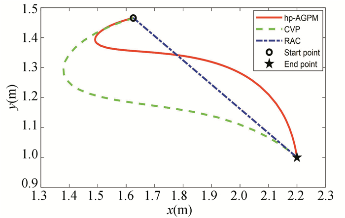
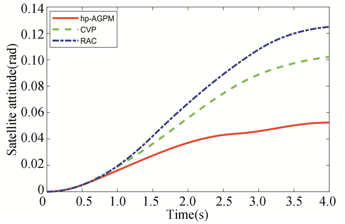
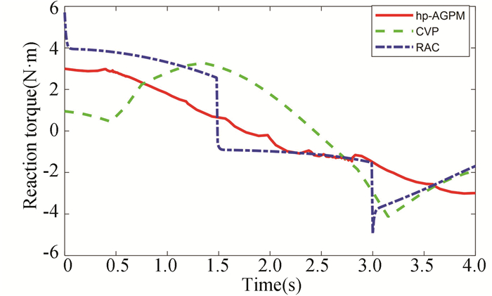
To evaluate performance of the proposed hp-AGPM, the obtained results were compared with the results of RAC and CVP methods presented in Refs.[25-26]. The results are shown in Fig. 4 to Fig. 6.
|
Fig.4 Trajectory of the end-effector |
|
Fig.5 Attitude curves of the satellite body |
|
Fig.6 Reaction torque at the satellite body |
Fig. 4 presents the comparisons of the position trajectories of the end-effector among the three methods. From the figure, we can see that all three methods can realize the motion of the end-effector from the initial position to final desired position. The trajectory of the end-effector generated by the RAC method is a straight line, and the trajectories generated by CVP method and hp-AGPM are curves.
Fig. 5 denotes the comparisons of the time histories of the satellite body's attitude angle among the three methods. As expected, the motion of manipulator will cause the attitude of satellite to change.From Fig. 5, we can see that the maximum attitude angle change of the satellite is equal to 0.0524 rad by using hp-AGPM, and the attitude angle of the satellite body for the CVP method and the RAC method are 0.1026 rad and 0.1237 rad respectively at the final time. Thus in the considered case hp-AGPM allowed reduction of the attitude angle of satellite by 48.93% and 57.64% from that of CVP method and RAC method, respectively. The validity of the proposed method in this paper is verified.
Fig. 6 illustrates the comparisons of the time histories of reaction torques applied to the satellite among the three methods. It can be seen that the reaction torque applied to the satellite using hp-AGPM is smooth, and there is no sudden change in the reaction torque during the motion.
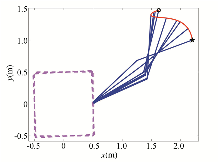
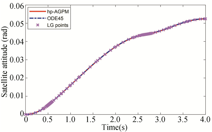
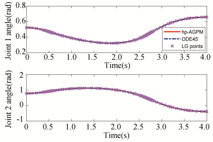
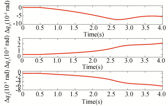
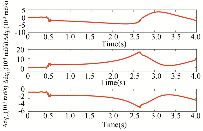
In order to verify the optimality of the path, the obtained control variables are interpolated by the cubic spline interpolation and substituted into the space robot dynamics model. The obtained results are taken as the actual state, as shown by the dotted line in Fig. 7 to Fig. 14.
|
Fig.7 Configuration change of the space robot |
|
Fig.8 Attitude displacement of the satellite body for hp-AGPM method |
|
Fig.9 Angles of manipulator joints |

|
Fig.10 Velocities of manipulator joints |
|
Fig.11 Errors of the joint angles |
|
Fig.12 Errors of the joint angular velocities |
|
Fig.13 State approximation points on various grids |

|
Fig.14 Hamiltonian vs time |
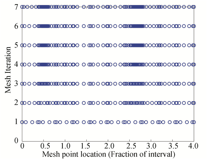
Positions of the satellite and manipulator during the maneuver with planned trajectory are presented in Fig. 7, and the result shows that the satellite attitude can be influenced by the motion of the manipulator. The time histories of satellite attitude are presented in Fig. 8. The angles and angular velocities of manipulator joints are shown in Fig. 9 and Fig. 10, respectively. In order to clearly see the differences of the angles and angular velocities between the hp-AGPM and the ODE45 method (Matlab function), the error curves are presented in Fig. 11 and Fig. 12. The results of Fig. 11 and Fig. 12 show that the relative errors of the angles and angular velocities of manipulator joints are small, and the optimality of the hp-AGPM is verified. State approximation points on various grids are shown in Fig. 13. The hp-AGPM can guarantee that it will be converged to an acceptable solution by 7 iterations. According to Pontryagin's maximum principle, the optimal Hamiltonian for this problem is constant (because the final time is constant) and Fig. 14 shows that the Hamiltonian is in excellent agreement with this theoretical result.
Table 2 shows the comparisons of performance of the algorithms using the h-method, p-method and the hp-AGPM. Through simulation, it was found that the p-method was never possible to obtain a solution for the tolerance ε≤10-3, so the h-method and hp-AGPM method were compared and analyzed.
| Table 2 Results comparison of different pseudospectral methods |
It can be seen from Table 2 that the CPU time and number of collocation points are similar for ε≥10-4. As the accuracy tolerance is tightened, the advantages of the hp-AGPM are gradually shown. The h-method requires more collocation points to achieve an acceptable tolerance, which significantly increased the computational cost when compared with the hp-AGPM. The hp-AGPM has great advantages in both the solving speed and the number of collocation points.
5 ConclusionsIn this paper, a path planning scheme of FFSR based on the hp-AGPM is proposed. The optimization objective of path planning is the minimum reaction torque of the satellite at terminal time. A planar 2-DOF FFSR is taken as an example to verify the proposed method. The simulation results show that the hp-AGPM can program an optimal trajectory of the end-effector of space robot in 10.6 s for the tolerance ε=10-6. It can be seen that the planned state variables and control variables are continuous and smooth and meet the path constraints.
The performances of hp-AGPM, CVP method and RAC method have been compared numerically with same simulation conditions. It has been shown that the hp-AGPM do significantly reduce the attitude disturbance for satellite at terminal time and provide a smooth trajectory of reaction torque at satellite body.
The hp-AGPM can automatically divide the segment or increase the number of collocation points. Compared with the p-method and h-method, the hp-AGPM has fewer collocation points and faster convergence speed, which is more suitable for solving the path planning problem of FFSR.
| [1] |
Stoll E, Letschnik J, Walter U, et al. On-orbit servicing. IEEE Robotics & Automation Magazine, 2009, 16(4): 29-33. DOI:10.1109/MRA.2009.934819 (  0) 0) |
| [2] |
Flores-Abad A, Ma O, Pham K, et al. A review of space robotics technologies for on-orbit servicing. Progress in Aerospace Sciences, 2014, 68: 1-26. DOI:10.1016/j.paerosci.2014.03.002 (  0) 0) |
| [3] |
Sun Z C, He J, Chen L H. Design of a three-finger dexterous hand driven by artificial torsional fibers for space debris capturing. Machine Design & Research, 2019, 35(1): 7-13. DOI:10.13952/j.cnki.jofmdr.2019.0090 (  0) 0) |
| [4] |
Moosavian S A A, Papadopoulos E. Free-flying robots in space: an overview of dynamics modeling, planning and control. Robotica, 2007, 25(5): 537-547. DOI:10.1017/S0263574707003438 (  0) 0) |
| [5] |
James F, Shah S V, Singh A K, et al. Reactionless maneuvering of a space robot in precapture phase. Journal of Guidance, Control, and Dynamics, 2016, 39(10): 2419-2425. DOI:10.2514/1.G001828 (  0) 0) |
| [6] |
Xu W F, Meng D S, Chen Y Q, et al. Dynamics modeling and analysis of a flexible-base space robot for capturing large flexible spacecraft. Multibody System Dynamics, 2014, 32(3): 357-401. DOI:10.1007/s11044-013-9389-0 (  0) 0) |
| [7] |
Jia Q X, Yuan B N, Chen G. Representation space analytical method for path planning of free-floating space manipulators. IEEE Access, 2019, 7: 54228-54251. DOI:10.1109/ACCESS.2019.2912905 (  0) 0) |
| [8] |
Gong J J, Chen Y Q. A nonlinear control method on the attitude control system of earth observation satellites. Chinese Space Science & Technology, 2001, 1(2): 69-74. (  0) 0) |
| [9] |
Madoery P G, Fraire J A, Finochietto J M. Analysis of communication strategies for earth observation satellite constellations. IEEE Latin America Transactions, 2016, 14(6): 2777-2782. DOI:10.1109/TLA.2016.7555254 (  0) 0) |
| [10] |
Rybus T. Point-to-point motion planning of a free-floating space manipulator using the rapidly-exploring random trees (RRT) method. Robotica, 2019, 38(6): 957-982. DOI:10.1017/S0263574719001176 (  0) 0) |
| [11] |
Okubo H, Nagano N, Komatsu N, et al. Path planning for space manipulators to reduce attitude disturbances. Journal of Guidance, Control, and Dynamics, 1995, 20(3): 609-611. DOI:10.2514/2.4086 (  0) 0) |
| [12] |
Flores-Abad A, Wei Z, Ma O, et al. Optimal control of space robots for capturing a tumbling object with uncertainties. Journal of Guidance, Control, and Dynamics, 2014, 37(6): 2014-2017. DOI:10.2514/1.G000003 (  0) 0) |
| [13] |
Flores-Abad A, Zhang L, Wei Z, et al. Optimal capture of a tumbling object in orbit using a space manipulator. Journal of Intelligent & Robotic Systems, 2017, 86(2): 199-211. DOI:10.1007/s10846-016-0417-1 (  0) 0) |
| [14] |
Wang M M, Luo J J, Walter U. Trajectory planning of free-floating space robot using Particle Swarm Optimization (PSO). Acta Astronautica, 2015, 112: 77-88. DOI:10.1016/j.actaastro.2015.03.008 (  0) 0) |
| [15] |
Betts J T. Survey of numerical methods for trajectory optimization. Journal of Guidance, Control, and Dynamics, 1998, 21(2): 193-207. DOI:10.2514/2.4231 (  0) 0) |
| [16] |
Zhang B Y, Zong Q, Dou L Q, et al. Trajectory optimization and finite-time control for unmanned helicopters formation. IEEE Access, 2019, 7(99): 93023-93034. DOI:10.1109/ACCESS.2019.2927817 (  0) 0) |
| [17] |
Wang Z, Wu Z. Six-DOF trajectory optimization for reusable launch vehicles via Gauss pseudospectral method. Journal of Systems Engineering and Electronics, 2016, 27(2): 434-441. DOI:10.1109/JSEE.2016.00044 (  0) 0) |
| [18] |
Huntington G T, Rao A V. Optimal reconfiguration of spacecraft formations using the Gauss pseudospectral method. Journal of Guidance, Control, and Dynamics, 2012, 31(3): 689-698. DOI:10.2514/1.31083 (  0) 0) |
| [19] |
Zeng X X, Cui N G, Guo J F. Path planning of space robot based on hp-adaptive pseudospectral method. Robot, 2018, 40(3): 385-392. DOI:10.13973/j.cnki.robot.170461 (  0) 0) |
| [20] |
Darby C L, Hager W W, Rao A V. An hp-adaptive pseudospectral method for solving optimal control problems. Optimal Control Applications & Methods, 2011, 32(4): 476-502. DOI:10.1002/oca.957 (  0) 0) |
| [21] |
Darby C L, Hager W W, Rao A V. Direct trajectory optimization using a variable low-order adaptive pseudospectral method. Journal of Spacecraft and Rockets, 2011, 48(3): 433-445. DOI:10.2514/1.52136 (  0) 0) |
| [22] |
Crain A, Ulrich S. Nonlinear optimal trajectory planning for free-floating space manipulators using a Gauss pseudospectral method. AIAA/AAS Astrodynamics Specialist Conference. Reston, VA: AIAA, 2016. DOI: 10.2514/6.2016-5272.
(  0) 0) |
| [23] |
Hou H. Convergence Analysis of Orthogonal Collocation Methods for Unconstrained Optimal Control. Gainesville: University of Florida, 2013.
(  0) 0) |
| [24] |
Hager W W, Hou H Y, Mohapatra S, et al. Convergence rate for a Radau hp collocation method applied to constrained optimal control. Computational Optimization and Applications, 2019, 74(1): 275-314. DOI:10.1007/s10589-019-00100-1 (  0) 0) |
| [25] |
Xu Y S, Kanade T. Space Robotics: Dynamics and Control. USA: Springer, 1993: 165-204.
(  0) 0) |
| [26] |
Zhang X, Zeng X X, Lang B. Path planning of free-floating space robot based on control variable parameterization method. Optics and Precision Engineering, 2019, 27(2): 372-378. DOI:10.3788/OPE.20192702.0372 (  0) 0) |
 2022, Vol. 29


