2. School of Civil Engineering, Chongqing Jiaotong University, Chongqing 400074, China
Traffic loading on bridges including probability distributions of axle loads and their static effects, dynamic impacts, vehicle-bridge interactions, fatigue loads as well as traffic simulation and prediction have been widely concerned during the past years, and a large number of progresses have been achieved[1-6]. Among them, the dynamic impact effects induced by travelling vehicles have been studied by many researchers. Since the interaction mechanism between vehicles and bridges is very complicated, it is difficult to estimate the dynamic impact effects accurately. To be convenient and practical, the dynamic impact factor IM is usually used to represent the impact effect of vehicles in bridge design and evaluation, serving as a constant or a function of span length/natural frequency/number of axles. However, previous studies point out that IM cannot be accurately described in specifications for most circumstances even with different expressions or values, by which contributions of various parameters related were partially ignored.
At present, the most general expression of IM having physical meaning and adopted by other studies[7-9] is
| $ {\rm{IM}} = \frac{{{\delta _{\rm{d}}}}}{{{\delta _{\rm{s}}}}} - 1 $ | (1) |
where δd and δs are the maximum dynamic and static response, respectively.
Specifically in China, IM is defined as a function of natural frequency of vibration for both highway bridges (JTG 2015)[10] and municipal bridges (CJJ2011)[11], both of which assume normal traffic situations. However, traffic congestion has become a ubiquitous phenomenon in many metropolises around the world, the impacts of which have been remarkably increasing in both magnitude and frequency. When traffic congestion takes place, bridge structures will subject to larger dynamic loads caused by vibration of idling engines, and roughness of bridge decks and concentrated vehicles. Note that the completed researches on impact factors mainly concern highway bridges. For instance, Deng et al.[8] studied the dynamic impact factors for simply supported bridges with different cross-section types, and analyzed how span lengths and cross-section types affect the impact factor. Shen et al.[9] simulated the distribution of dynamic impact factor produced by vehicle-bridge coupling vibration as a random parameter. Yu et al.[12] analyzed the local impact effect for deck slabs of pre-stressed concrete box-girder bridges subjected to vehicle loading. Han et al.[13-14] analyzed the dynamic impact of heavy trucks/extra overloaded trucks on typical highway bridges using WIM data. Everitt et al.[3] studied the dynamic load effects of special oversized and heavy vehicles on a steel girder composite bridge. However, the impact force generated from idling vehicle-bridge vibration in traffic congestion on municipal bridges is quite different from that in normal traffic on highway bridges, due to different excitation sources, number of vehicles, and freedom of movement, thus the completed research may not be applicable. On the other hand, previous research has reported that the impact factors provided in Chinese codes tend to be unsafe[15]. Normally, the fundamental frequency of a bridge is the most important factor with respect to the dynamic impact effect[8], while the revolving speeds of idling engines range from 600 r/min to 800 r/min. The corresponding frequencies are between 10.0 Hz and 13.3 Hz, which happen to be in the range of the fundamental frequencies of 1.23 Hz to 14 Hz for most bridges, indicating the dynamic impact effects may be amplified due to traffic congestion and great difference from those in normal traffic situation. Therefore, it is necessary to address the issue of idling vehicle-bridge vibration and reveal its characteristics at aspects of methodology and mechanism.
In addition, it is very difficult to obtain vehicle data including gross weight, axle weight, headway distance, etc. During traffic congestion, although the data collecting technique of weigh-in-motion (WIM) system has been widely used on highway bridges, where the installed sensors at the beginning of bridges could measure axle loads, axle spacings, and speeds while vehicles run freely, it seems not appropriate for municipal bridges under traffic congestion, when all vehicles densely spread without moving or moving at a very slow speed less than 5 km/h. Consequently, conducting analysis on idling vehicle-bridge vibration becomes challenging and complicated. In order to solve the problems mentioned above, this study is to propose a data collecting method especially for vehicles in traffic congestion. This method is applied to a municipal bridge suffering from severe congestion to collect data of a large amount of real traffic congestion scenarios. By utilizing the data, congestion load models as well as the idling vehicle-bridge coupling models are developed to calculate the corresponding dynamic impact factors. Compared with code provision, a calibration factor is recommended for bridge design considering vehicle-bridge coupling vibration under heavy traffic congestion.
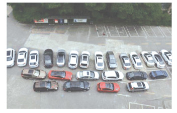
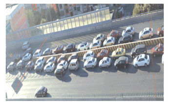
1 Data Collecting Method and Load Model Development 1.1 Data Collecting MethodTraffic congestions often occur during rush hours presenting obvious periodical features. When vehicle platoons arrange along bridge span and rarely change, continuously capturing typical congestion scenarios with high definition camera at certain location could be an effective approach to get the first hand information. Taking advantage of image processing software and combining the scale plate and measurement marked at the site before field investigation, image information digitization is implemented based on perspective principle. The accuracy and efficiency of this method have been tested before field investigation as illustrated in Fig. 1. A parking lot was chosen to carry out the test. After this, a typical municipal bridge suffering from daily heavy traffic congestion was selected to do data collecting, as shown in Fig. 2. About 6000 typical congestion images were collected from September to November at Urumqi City. Finally, a database consisting of 160 vehicle types was established by image data processing.
|
Fig.1 The testing at a parking lot |
|
Fig.2 An example of the field investigation |
1.2 Vehicle Load Models
As a matter of fact, the vehicle type appearing on municipal bridges is relatively regular and simple, and the majority is sport utility vehicles and automobiles. Since no weighing equipment was available during congestion, the parameters in sample databases established by automobile companies were taken for axle load and axle spacing, where the reduction factor was also taken into account for fully loaded axles[16]. By means of the maximum likelihood method, the distributions and confidence intervals of axle loads and axle spacings were obtained. The other two random parameters, namely, the distance between the first vehicle and the beginning of the bridge and that between the last vehicle and the end of the bridge, are defined as vehicle-bridge-distance hereafter; the distance between the two close axles of adjacent vehicles, defined as vehicle-distance hereafter, could be measured according to the digital data processed above as well as their statistic parameters. It is notable that these two distances are particular parameters for traffic congestion situation, reflecting the locations of vehicles on the bridge.
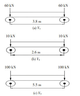
To be convenient, regular automobile, sport utility vehicle, minibus and minicab are classified into Type 1 (V1), light/medium bus Type 2 (V2), coach and bus Type 3 (V3), then the distributions of axle load, axle spacing, vehicle-bridge-distance, and vehicle-distance defined above were found for each vehicle type. For each parameter, the collected data was used to conduct distributing fitting testing by the normal, lognormal, weibull, gamma, and extreme distribution to find the best one. In addition, the corresponding statistic parameters were also estimated by taking the maximum likelihood estimation to ensure a probability of non-exceedance of 95%. It was notable that the representative value of axle load was equal to the unloaded axle weight of 7.7 kN plus the passenger weight of 3 kN, and its approximate value of 10 kN was adopted. The probability distributions and statistic parameters of V1 are shown in Table 1 as an example. Similarly, the representative values of main parameters were calculated for the other two vehicle classes. Due to the limited space, the details were not presented here, but three vehicle models were developed in Fig. 3.
| Table 1 The probability distributions and statistic parameters of type V1 |
|
Fig.3 Schematic of vehicles in congestion situation |
1.3 Congestion Load Model
According to the field investigation, it was found no matter how many vehicle types were contained in the traffic flow, those appearing on municipal bridge during traffic congestion were relatively analogous, due to traffic restriction implemented in most metropolises. Among them, V1 was the majority while V2 and V3 took a small portion. Ultimately, six congestion load models are shown in Table 2.
| Table 2 Congestion load models and their components |
2 Idling Vehicle Vibration Model
Traditional vehicle-bridge coupling vibration indicated the contact point between the bridge and the vehicle when travelling at a certain speed. On the contrary, the dynamic impact effect produced by the vibrating of idling vehicle engines congested on bridges was the objective in the present study. Thus, the previous interaction equations derived for vehicle-bridge vibration were not applicable here[7, 14, 17]. In this section, the dynamic vehicle load represented by the vibration of idling engine was simulated, so was the corresponding vehicle structure.
2.1 Simulation of Dynamic Vehicle LoadAs far as idling condition was concerned, it indicated the engine rotated without loading but by overcoming self-resistance only. Essentially, the working manner of engine was embodied by the continuous circulatory movement of the mechanical components so that the produced dynamic force by idling rotating could be expressed as a sine function[18]:
| $ F = {F_{\rm{d}}}{\rm{sin}}\; (\omega t) $ | (2) |
where Fd was the amplitude of the dynamic load, generated by the unbalanced driving force of engine. It can be seen from Eq. (2) that the dynamic load was determined by the three key factors of frequency, amplitude, and phase, corresponding to engine revolution, unbalanced driving force, and the starting time, respectively. In the present study, the instantaneous state of starting and stopping was ignored, and it was assumed that all idling engines rotated simultaneously. Commonly, the idling engine speed ranges from 600 to 800 r/min (the corresponding frequency is 10.00 to 13.33 Hz), thus three types of idling engine speed, 600, 700 and 800 r/min were considered. In addition, according to the research work of Wang[19], with respect to the relationship of the vehicular vertical load and its external acceleration, the ratio of the amplitude of dynamic load Fd to the static load Fs was proportional to the acceleration, for which a value of 0.2 g was recommended, and the ratio of Fd to Fs was taken as 0.2. Consequently, the amplitude of the dynamic load was 4, 24 and 40 kN for vehicle type 1, 2, and 3, respectively. Then, a computation program was developed by MATLAB to generate the time history of vehicle engines.
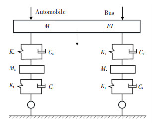
2.2 Vehicle Structure ModelIn the congestion situation, the two sides of vehicle body moved in the same way and only had the vertical freedom. In this case, the semi-vehicle structure was appropriate to simulate the idling vehicle. Semi-vehicle structure was mainly composed of vehicle body, suspension, and tire, considering the stiffness and non-uniform mass (eccentric centroid) of vehicle body, the stiffness and damping of suspensions and tires. combining the features of idling vehicles, three aspects could be simplified as follows: 1) simplification of freedom, only the dynamic effect caused by the vertical vibration was taken into account; 2) uniform body mass was assumed; 3) the same stiffness and damping were assumed for the front and rear suspensions and tires. In this way, the simplified vehicle structure was plotted in Fig. 4, and the involved parameters were listed in Table 3 for the three vehicle types developed before. Noting that engine was placed at the front of automobile and in the rear of bus respectively, the dynamic force should be loaded at the front and rear correspondingly.
|
Fig.4 Analytical vehicle model |
| Table 3 Parameters of the three vehicle types |
3 Dynamic Impact Factor for Idling Vehicle-Bridge Vibration 3.1 Bridge Model
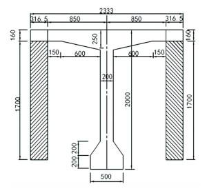
To be consistent, the bridge being investigated was also adopted in this section. It locates at a key position in the city traffic network and is a pre-stressed continuous T-girder bridge with three spans of 30 m, designed according to the Chinese municipal bridge code using A-class live load. This bridge consists of four identical concrete T-girders with a roadway width of 9.25 m and there are two lanes in one direction. The cross section of the bridge was illustrated in Fig. 5 with detailed dimension. As described before, the fundamental frequency of a bridge would affect the dynamic impact to a large extent, so the natural frequencies of the bridge interested was firstly studied by building finite element model. The first ten frequencies were listed in Table 4, and only the first four modes were plotted in Fig. 6 due to the limited space. There five vertical modes and five bending and torsion modes appeared alternatively. Although the 7th to 10th frequencies were very close to the vibration frequency of the idling speed of 600 r/min, resonance rarely happened because tremendous stimulation was needed when it came to high-order modes.
|
Fig.5 Cross section of the real bridge (mm) |
| Table 4 The first 10 modes of the bridge (Hz) |

|
Fig.6 The first four modes of the investigated bridge |
3.2 Analytical Model for Idling Vehicle-Bridge Coupling Vibration
In most studies, the interaction of vehicle and bridge was regarded as two independent subsystems, and motion equations were derived for each system[20-22]. Adding the displacement coordination principle and force balance at the contact point of the two, the combined motion equations could be solved by iterative method. However, this traditional analytical method was not applicable to idling vehicle-bridge interaction as demonstrated above. For this particular case, the motion equation could be developed based on structural dynamics. Specifically, the differential equation of single freedom system with viscous damping under resonant force action is expressed as below:
| $ m\ddot u + c\dot u + ku = {p_0}{\rm{sin}}\; (\omega t) $ | (3) |
and the initial condition is
| $ u = u(0), \dot u = \dot u(0) $ | (4) |
To solve the Eq.(2), the particular solution is
| $ {u_p}(t) = C{\rm{sin}}\; \omega t + D{\rm{cos}}\; \omega t $ | (5) |
where
| $ C = \frac{{{P_o}}}{k} \cdot \frac{{1 - {{\left( {\omega /{\omega _n}} \right)}^2}}}{{{{\left[ {1 - {{\left( {\omega /{\omega _n}} \right)}^2}} \right]}^2} + {{\left[ {2\xi \left( {\omega /{\omega _n}} \right)} \right]}^2}}} $ | (6) |
| $ D = \frac{{{P_o}}}{k} \cdot \frac{{ - 2\xi \omega /{\omega _n}}}{{{{\left[ {1 - {{\left( {\omega /{\omega _n}} \right)}^2}} \right]}^2} + {{\left[ {2\xi \left( {\omega /{\omega _n}} \right)} \right]}^2}}} $ | (7) |
The residual solution is
| $ {u_c}(t) = {{\rm{e}}^{ - \zeta {\omega _n}t}}\left( {A{\rm{cos}}\; {\omega _n}t + B{\rm{sin}}\; {\omega _n}t} \right) $ | (8) |
where
Then, the comprehensive solution of Eq.(3) is
| $ \begin{array}{l} u(t) = {{\rm{e}}^{ - \zeta {\omega _n}t}}\left( {A{\rm{cos}}\; {\omega _n}t + B{\rm{sin}}\; {\omega _n}t} \right) + C{\rm{sin}}\; \omega t + \\ \;\;\;\;\;\;D{\rm{cos}}\; \omega t \end{array} $ | (9) |
where constant A and B are obtained from the initial condition.
Note that the response u(t) contains transient vibration and forced vibration. The former would produce the maximum dynamic effect but attenuate sharply, having short acting time; the latter would impact frequently during a long time.
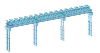
To make the analytical method more practical and applicable, extremely complicated theoretical calculation was avoided in this study. The idling vehicles and the bridge FE model were coupled with rigid connections, considering the deformation coordination relationship at the contact points of the two[23]. After that, the congestion load models proposed were loaded on the coupled model. In each loading case, the involved vehicle models were arranged along the span according to their vehicle-distance, and lateral eccentric loading was taken as the most unfavorable condition. The ultimate FE model of idling vehicle-bridge coupling is illustrated in Fig. 7. Besides, the immediate integration method was adopted and transient time history was selected. Testing results showed the duration of 6 s was sufficient to reflect the whole vibrating process. Damping was calculated by strain energy factor.
|
Fig.7 FE model for idling vehicle-bridge coupling |
3.3 Dynamic Impact Factor
At first, the six traffic congestion models proposed in Table 2 were loaded to calculate the dynamic effects of vehicle-bridge interaction, including dynamic displacement and stress time-history curves. Then, the ratios of the maximum dynamic displacement/stress to the maximum static displacement/stress in steady-state vibration were defined as the dynamic impact factor of the vehicle-bridge interaction in congestion case to reflect the dynamic action of idling vehicle platoons on bridge structures. Its counterpart is (1+ μ) defined in Chinese codes for bridge design. The calculation results of congestion model 1 to 6 were plotted in Fig. 8 below, which shows that it could be seen that the gross vehicle weight (GVW) and the mass and damping of vehicle suspensions would significantly influence the dynamic effects at the mid-span. For example, M1 has smaller GVW and M6 has larger damping. The two produced smaller dynamic impact factors are compared with others. M2 and M3 induced very great impact force to the side-span. The corresponding dynamic impact factor is ten times as large as those of other four loading cases. On the other hand, M2, M3, and M5 consisting of alternative vehicle types caused larger stresses at the bottom of the girder on piers compared with those of M1, M4, and M6, which have identical vehicle type. On the basis of the General Code for Design of Highway Bridges and Culverts[10], the fundamental frequency of this continuous bridge is 2.96 Hz and the impact factor μ is taken as 0.176 accordingly, so the dynamic factor (1+ μ), as defined in this study, is 1.176. By comparison, the maximum dynamic impact factors calculated using all congestion models proposed in the present study were 1.15, 1.33, 1.50, 2.38, 2.67, and 1.29 times as large as the code provision value, respectively. Thus, it can be concluded that the impact factor taken for bridge design and evaluation should not be the same as the specified value when considering vehicle-bridge coupling vibration under traffic congestion situation, and a mean value of 1.7 was recommended as the calibration coefficient for the impact factors in codes, based on the calculated results here.

|
Fig.8 Dynamic impact factors of displacement and stress in six loading case |
4 Conclusions
In the present study, a truck data collecting method was proposed for traffic congesting, and the continuously collected data from a municipal bridge in field was used to develop congestion load models. Besides, the external excitation was simulated, and the finite element model of vehicle-bridge coupling vibration was established based on the derived motion equations. Then, the dynamic impact factors produced by the six loading cases were calculated and compared with the code provision value. Consequently, the following conclusions could be drawn from this study:
1) According to the field investigation, it was found automobile, sport utility vehicle, minibus and minicab composed the majority of traffic volume, and their statistical axle weight, axle spacing, vehicle-bridge-distance, and vehicle-distance follow nonparametric kernel density, lognormal, weibull, and normal distribution, respectively.
2) The arrangement of vehicles similar to M2 and M3 with heavy middle and light sides would induce severer impact effect on the sidespan, compared with other four congestion load models of M1, M4, M5, and M6, the former was even ten times larger.
3) Congestion load models of M2, M3, and M5, consisting of alternative vehicle types, caused larger stresses at the bottom of the girder on piers, compared with those of M1, M4, and M6, which were composed of identical vehicle types. Specifically, the former case was greater than the latter case by 19%.
4) The maximum dynamic impact factor calculated from six congestion loading cases was 1.15, 1.33, 1.50, 2.38, 2.67, and 1.29 times as large as the code provision value, respectively. Thus, the impact factor taken for bridge design and evaluation needs to be calibrated rather than to use the code directly, when considering vehicle-bridge coupling vibration in traffic congestion situations. A calibration factor of 1.7 is recommended in this study.
| [1] |
Anitori G, Casas Rius J R, Ghosn M. WIM-based live-load model for advanced analysis of simply supported short-and medium span highway bridges. Journal of Bridge Engineering, 2017, 22(10): 04017062. DOI:10.1061/(ASCE)BE.1943-5592.0001081 (  0) 0) |
| [2] |
Barker M G, Puckett J A. Unique truck loads on interstates in Wyoming and similar states and the impact on bridge safety design. Journal of Bridge Engineering, 2019, 24(2): 1-12. DOI:10.1061/(ASCE)BE.1943-5592.0001312 (  0) 0) |
| [3] |
Everitt A, Dagenais M A, Wight G. Dynamic load effects of wheeled and tracked military vehicles on a steel girder composite bridge. Journal of Bridge Engineering, 2021, 26(3): 04020132. DOI:10.1061/(ASCE)BE.1943-5592.0001672 (  0) 0) |
| [4] |
de Freitas S T, Kolstein H, Bijlaard F. Fatigue assessment of full-scale retrofitted orthotropic bridge decks. Journal of Bridge Engineering, 2017, 22(11): 4017092. DOI:10.1061/(ASCE)BE.1943-5592.0001115 (  0) 0) |
| [5] |
González A, Cantero D, OBrien E J. Dynamic increment for shear force due to heavy vehicles crossing a highway bridge. Computers and Structures, 2011, 89(23-24): 2261-2272. DOI:10.1016/j.compstruc.2011.08.009 (  0) 0) |
| [6] |
Iatsko O, Nowak A S. Revisited live load for simple-span bridge. Journal of Bridge Engineering, 2021, 26(1): 04020114. DOI:10.1061/(ASCE)BE.1943-5592.0001647 (  0) 0) |
| [7] |
Deng L, Duan L L, He W, et al. Study on vehicle model for vehicle-bridge coupling vibration of highway bridges in China. China Journal of Highway and Transport, 2018, 31(7): 92-100. (  0) 0) |
| [8] |
Deng L, He W, Wang F. Dynamic impact factors for simply supported bridges with different cross-section types. Journal of Vibration and Shock, 2015, 34(14): 70-75. DOI:10.13465/j.cnki.jvs.2015.14.013 (  0) 0) |
| [9] |
Shen R L, Guan K, Fang K. Probability distribution of random variables of impact coefficient in numerical simulation of vehicle-bridge coupled vibration. Journal of Vibration and Shock, 2015, 34(18): 123-128. DOI:10.13465/j.cnki.jvs.2015.18.021 (  0) 0) |
| [10] |
Ministry of Communications. JTG 2015. General Code for Design of Highway Bridges and Culverts. Beijing: Ministry of Communications, 2015.
(  0) 0) |
| [11] |
Ministry of Housing and Urban-Rural Development. CJJ2011. Code for Design of the Municipal Bridge. Beijing: Ministry of Housing and Urban-Rural Development, 2011.
(  0) 0) |
| [12] |
Yu Y, Deng L, Wang W, et al. Local impact analysis for deck slabs of prestressed concrete box-girder bridges subjected to vehicle loading. Journal of Vibration and Control, 2017, 23(1): 31-45. DOI:10.1177/1077546315575434 (  0) 0) |
| [13] |
Han W S, Wu J, Cai C S, et al. Characteristics and dynamic impact of overloaded extra heavy trucks on typical highway bridges. Journal of Bridge Engineering, 2015, 20(2): 05014011-1-11. DOI:10.1061/(ASCE)BE.1943-5592.0000666 (  0) 0) |
| [14] |
Han W S, Yuan Y G, Huang P M, et al. Dynamic impact of heavy traffic load on typical T-beam bridges based on WIM data. Journal of Performance of Constructed Facilitites, 2017, 31(3): 04017001-1-14. DOI:10.1061/(ASCE)CF.1943-5509.0000991 (  0) 0) |
| [15] |
Liu S, Wang Z L. Discussion on the impact factor of the old and the new specification. China Science and Technology Information, 2005, 23: 121-128. (in Chinese) (  0) 0) |
| [16] |
Li H, Li W Q. Study on the loading factor of bus dispatch in cities. Journal of Traffic and Transportation Engineering Information, 2008, 6(4): 104-109. (  0) 0) |
| [17] |
Yuan S J. Development and Programming of Typical Vehicles Equation of Motion for Coupling Vibration between Highway Bridge and Vehicles. Xi'an: Chang'an University, 2012.
(  0) 0) |
| [18] |
Hu Y L. Dynamic and Static Analysis of Urban Bridge under the Effect of Vehicle Jam. Guangzhou: South China University of Technology, 2012. (  0) 0) |
| [19] |
Wang X F. The Design of Automotive Chassis. Beijing: Tsinghua University Press, 2010. (  0) 0) |
| [20] |
Kim C W, Kawatani M, Kim K B. Three-demensional dynamic analysis for bridge-vehicle interaction with roadway roughness. Computers & Structures, 2005, 83(19-20): 1627-1645. DOI:10.1016/j.compstruc.2004.12.004 (  0) 0) |
| [21] |
OBrien E J, Cantero D, Enright B, et al. Characteristic dynamic increment for extreme traffic loading events on short and medium span highway bridges. Engineering Structures, 2010, 32(12): 3827-3835. DOI:10.1016/j.engstruct.2010.08.018 (  0) 0) |
| [22] |
Wang W, Deng L, Shao X D. Fatigue design of steel bridges considering the effect of dynamic vehicle loading and overloaded trucks. Journal of Bridge Engineering, 2016, 21(9): 04016048. DOI:10.1061/(ASCE)BE.1943-5592.0000914 (  0) 0) |
| [23] |
Zhang X Y, Peng X, Ma J S, et al. The comparative analysis of two contact models in vehicle-bridge coupled vibration. Proceedings of the 21st Structural Engineering Conference. Beijing: Chinese Society of Mechanics, 2012. 333-336.
(  0) 0) |
 2022, Vol. 29


