With the advancement of technology, composite materials are the key alternate to conventional engineering materials due to their excellent characteristics like high strength, low-density, low cost, and eco-friendly manufacturing process[1]. Composite material is a system of two or more physically and chemically distinct materials which possess improved properties compared with the individual constituent materials. It is composed of a binding material termed a matrix and a reinforcing filler to enhance the strength and stiffness of the matrix. The benefits of combining different constituents are to exploit the superior properties of both materials without trading off the individual property[2]. Carbon, which is the sixth element in the periodic table in its single entity and various forms, is truly notable for its extraordinary ability of catenation to mix with itself and other chemical elements in many ways to build the foundation of life. It is copiously available in nature as coal or natural graphite, but has less quantity than diamond[3]. Man has created other different forms of carbon such as synthetic diamond, synthetic graphite, carbon black, charcoal, and conjugated carbon nanomaterials such as carbon nanotubes and fullerenes that have been used as energy materials in electrode and electrical contact, high-performance aircraft, tennis rackets, spacecraft components, etc.[4] All of these types of carbon can be recognized for the special hybridization properties of carbon. The orbital arrangement of carbon atoms in the ground state is 1S2, 2S2, 2P2. The energy difference between 2S and 2P orbital accelerates the promotion of 2S electron to an unfilled higher energy 2P orbital. This electron acceleration allows the carbon to hybridize into SP, SP2, and SP3 configuration, resulting in a variety of molecular structures.
In the advanced research era of the nanocomposite, due to exceptional thermal, mechanical, chemical, and electrical properties, lots of prominences have been given favoring the carbon-based nanofillers, i.e., carbon nanotube. Different forms of carbon nanostructures have established applications in various areas like the drug industry, composite materials, energy storage, conversion, sensors, and field emission devices, etc.[5] Carbon nanotube as compared with other carbon materials is found to be the best reinforcements in composites due to high tensile strength (≥10 GPa), high modulus of about 1 TPa, and low density of 2.1 g/cm3. A variety of nanocomposites have been fabricated by embedding CNT filler into various polymer matrices such as epoxy, polypropylene (PP), and polyamides. Epoxy resin is the effective polymer matrix mostly used for strengthening nanotubes. This class of matrix possesses surprising specific strength, stiffness, and chemical affinity towards the filler materials[6]. Epoxy resin has been preferably used for various structural applications as well as in various microelectronics applications due to its tailored mechanical and chemical properties.
Recently, the use of MWCNT as filler in the polymer matrix has attracted considerable interest due to its unique properties. Zhou et al.[7] found the use of 3 wt% of nanofiller enhanced the young's modulus of the composite near about 19.4%. Another study by Montazeri showed that 0.5% increase in filler content increased the tensile strength and young's modulus significantly[8]. Yeh et al.[9] studied the influence of nanoparticles shape factor (l/d) upon the mechanical properties of the composite. The authors found that nanocomposite samples having higher shape factors exhibit higher mechanical properties than the ones with lower shape factors. However, the main concern in preparing nanocomposites is the dispersion problem, which affects the electron movement and dipole-dipole interactions[10]. The entangled carbon-carbon atoms in nanotube establish a striking force among themselves, which needs to be physically and chemically dispersed to minimize aggregation[11]. Improper distribution of CNTs in the matrix causes inferior interfacial bonding and hence the nanotube surfaces must be functionally activated for better adhesion[12]. Kausar et al.[13] studied the effects of acid-treated and untreated multi-walled carbon nanotube on the mechanical properties of epoxy reinforced polysulfide. They found that acid treatment carbon nanotube possesses comparatively better mechanical properties because of better dispersion within the continuous medium. Yang et al.[14] studied the consequence of an epoxy matrix utilizing a chemically-treated mixture of H2SO4 and HNO3 with multi-walled CNT. It has been found that uniform distribution and better interfacial bonding enhance the overall properties of the composite. Better fabrication techniques enhance the mechanical, thermal, and electrical properties tremendously. Some literature shows that ultrasonication in comparison with the shear mixing method gives superior nanoscale dispersion according to scanning electron microscopy (SEM).
Various fabrication techniques have been found in past literature for polymer composites. Solution processing[15], melt mixing[16] and resin transfer moulding[17] techniques are very common for various thermosetting and thermoplastic polymers. Ultrasonication[18] or the shear mixing technique is the most frequently used technique for nanoparticle dispersion. To improve the bonding between phases, different techniques like attachment of functional group and in situ polymerization[19] may be employed. In the twin-screw extrusion process, the large agglomerates are broken up into small particles to facilitate better dispersion of CNT throughout the matrix. Presently, researchers are in quest of new approaches to fabricate the nanocomposites with a uniform dispersion of reinforcement materials into the matrix. Different micromechanical models assuming a homogeneous distribution of fillers into the matrix are proposed to explain the different properties of nanocomposites.
Many researchers have reported works on the carbon nanotube[20-21], carbon black[15-16], and graphite[22] in the domain of mechanical, thermal, and electrical characterization. However, there is a restricted number of works available on the low percentage of filler material containing composite materials. Further, past research works suggest that the percolation threshold can be achieved at a very low weight fraction of CNT filler, but a limited number of works are reported. Though CNTs possess an excellent combination of thermal, electrical, and mechanical properties, the effectiveness of the same has been traded off due to agglomeration and improper bonding of CNTs surface and the polymer matrix. This challenge can be easily overcome by employing functionalization to the nanotube filler[23]. The works on epoxy composite containing a low fraction of CNT and the effects of the process variable are insufficiently available.
In the present work, polymeric fibrous composites using different carbon-based fillers such as carbon black, graphite, and CNT are fabricated. For CNT reinforced composite material, the nanotubes are pre-activated by covalent functionalization. Mechanical, thermal, and electrical properties are evaluated for the synthesized composites and a comparison is made to assess the suitability for various applications.
1 Experimental Details 1.1 Materials and Composite FabricationFour different fibrous polymeric composite specimens were prepared by taking different weight percentages of filler materials such as carbon black 6.0%[24], graphite powder 4.0%[25], and MWCNT(1.0%, 1.5%). Thermal and mechanical characterizations were carried out. The optimum content of carbon black and graphite were regarded as effective fillers to cause a noticeable improvement in the desired composite properties. The average outer diameter of the carbon nanotube was taken as 20-30 nm and length was 10-30 μm. The particle size of graphite powder was taken as 60 μm. Another filler material carbon black (VULCAN XC72R) (20-60 nm in diameter according to TEM observation) was taken. Epoxy, used as matrix materials, which belongs to a class of reactive polymer that contains the epoxide group, may be reacted with hardeners by curing/cross-linking reaction to form a thermosetting polymer.
1.1.1 Carbon black(CB)CB is the black pigment traditionally produced from charring organic material such as wood or bone. CB is fine particles with an average size of 30 nm. Its maximum ash content percentage is 0.2, and it has a density of 1.7-1.9 g/cm3. It has higher specific area due to its smaller size of the particles.
1.1.2 GraphiteGraphite is an allotrope of carbon that is in a crystalline form where the carbon atom is arranged in a hexagonal structure. Under standard conditions, it is the most stable form of carbon with an average particle size of 60 μm. It possesses higher electrical conductivity than that of diamond due to the delocalization of π-electrons of a carbon atom.
1.1.3 Carbon nanotube (CNT)CNT looks like powder or black soot with a cylindrical carbon structure that has hexagonal graphite molecules attached at the edges. The average outer diameter of the carbon nanotube was taken as 20-30 nm and the length was 10-30 μm.
1.1.4 Epoxy resinThe epoxy resin used in this study was the diglycidyl ether of bisphenol. DGEBA is a liquid epoxy resin that constitutes overall 75% of the resin used in any industrial applications. DGEBA is a common commercial epoxy resin and it was processed by the reaction of bisphenol-A and epichlorohydrin in presence of a catalyst. It is marketed under the trade name Araldite GY 257.
1.2 Functionalization of MWCNTDispersion of CNT into the matrix is a challenging task owing to the lack of its chemical affinity between the CNTs and polymer. Though CNTs have excellent properties, the closed surface of CNT cannot give better physical interactions with the matrix. To avoid the difficulties, functionalization is highly essential. MWCNT was treated with sulfuric acid and nitric acid in the ratio of 3∶1 and underwent a sonication process at 400 ℃. Then distilled water was added to dilute the solution. H2SO4 and H2O2 at a ratio of 4∶1 were added to the above mixture. Then the mixture was diluted with 250 mL of distilled water and water was decanted with a dropper to remove the acid. Then CNT solution was centrifuged several times to remove the acid and separate the CNT. Then the pH value was checked to see whether the solution has a pH of 6-7. Then the collected CNT was poured on a Petri dish and kept in an oven for one night at 50 ℃. Then the dried CNT was grinded with mortar and pestle, collected in a zipper to keep the functionalized MWCNT away from moisture. In addition to functional groups, both sides of CNT were opened and ready to bond with matrix materials.
1.3 Fabrication of NanocompositesThe desired composites were obtained by mixing the desired amount of carbon black (4.0%), graphite (6.0%), CNT (1.0%, 1.5%) by weight with epoxy resin utilizing a mechanical stirrer. After that, the mixture was placed in an oven at 50 ℃ for 2 h. To obtain uniform dispersion, hardener HY951 was mixed and stirred for 15 min. Then composite laminates were fabricated using compression molding for the preparation of different sheets of dimension 180 m×180 m. Then the samples were placed at room temperature for the curing cycle of 24 h duration. Table 1 shows the different proportions of fillers and matrices for different batches.
| Table 1 Proportion of fillers and matrix for batch mixing |
1.4 Nanocomposites Characterization Methods 1.4.1 Thermal conductivity
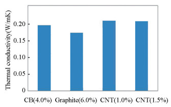
Thermal conductivity (W/mK) is the product of specific heat (J/gK), thermal diffusivity (mm2/s), and density. In the present study, it was measured using Unitherm 2022 (AnterCorpo, USA) according to ASTM E1530 standard by taking circular disc specimens of 50 mm diameter and 3 mm thickness. The surface finishes of the specimens were enhanced by finishing through fine emery paper to obtain a precise measurement. The measured values of thermal conductivity of the specimens at a temperature of 30 ℃ are presented in Fig. 1.
|
Fig.1 Thermal conductivity v.s. different filler content of composite |
1.4.2 Differential scanning calorimetry (DSC)
DSC was performed to study the curing behavior of the composite. In the beginning, the calorimeter was calibrated by using Indium and Zinc. The readily surface-treated reinforcement materials were uniformly dispersed within the matrix. The mixture was then placed in aluminum pans and covered with aluminum lids. The specimens were kept at room temperature for 10 min. The DSC was carried out in an environment of 20 to 3000 ℃ at a heating rate of 100 C/min for the composite specimens weighing 10 mg each.
1.4.3 Electrical conductivityThe AC conductivity of the samples was calculated by AC impedance spectroscopy using impendence analyzer (LCR Meter, Model: IM 3370) in the range from 10 Hz to 100 MHz. The dielectric constant, resistance, and capacitance of the samples were measured by applying different voltages to the specimen's upper and lower surfaces. The corresponding AC conductivity is calculated using Eq. (1):
| $ {T_{{\rm{AC}}}} = {\varepsilon _0}{\varepsilon _r}\omega \;\tan \;\varphi $ | (1) |
where ε0 represents dielectric permittivity in free space, εr represents dielectric constant, ω equals to 2πf and represents angular frequency, and tanφ represents dielectric loss.
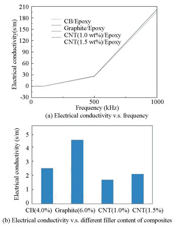
The experimental results of the specimens found at frequency 1000 Hz are presented in Fig. 2.
|
Fig.2 Electrical conductivity v.s. different filler content of composites |
1.4.4 Fourier transform infrared (FTIR) analysis
FTIR is an important analytical technique for the simultaneous determination of organic components including bond as well as organic content (protein, carbohydrate, and lipid). In the FTIR analysis procedure, samples are exposed to contact with infrared (IR) radiation, which has an effect on the atomic vibrations of a molecule in the samples that follow the specific absorption/transmission of energy.
1.4.5 Tensile strengthThe tensile strength of the composite materials was measured by tensile tests according to ASTM standard by using Instron Universal testing machine UTE 20 HGFL, fuel instruments, and engineers Pvt. Ltd. at a strain rate of 1 mm/min. Rectangular composite samples with a dimension of 190 m×165 m×3 m were tested. The mechanical properties of the material such as tensile strength, young's modulus, and elongation at failure were measured at room temperature.
1.4.6 MicrohardnessMicrohardness of all composite specimens was measured by using a digital microhardness tester MMT-X3 (MATSUZAWA Co, Ltd.). Both surfaces of composites were polished with the help of sandpaper to acquire a smooth surface for indentation. Vickers Diamond Pyramid Indenter was utilized for the test with an indenter having an included angle of 136° between opposite faces of a pyramid. 100 gm-force was used for 15 s to get the indentation. Ten points in each composite were measured to get average readings. The hardness is determined by Eq. (2):
| $ {\rm{HV}} = 1.85L/{d^2} $ | (2) |
where L is the load applied in the unit of gm and d is the diagonal length of the diamond impression of the indentation in the unit of mm.
1.4.7 SEMAn intense beam of high-energy electrons is used by SEM to generate a variety of signals at the surface of solid specimens (epoxy resin/carbon black). The SEM micrographs reveal information about the surface morphology, chemical composition, and crystalline structure, and the orientation of constituents' materials. It also provides information about the spatial variations in 2D images. In addition, it can analyze the point location of the sample.
2 Results and Discussion 2.1 Thermal PropertiesThe composites prepared with various allotropes of carbon such as carbon black, graphite, and multiwalled CNT were subjected to tests to measure their thermal conductivity and glass transition temperature.
2.1.1 Thermal conductivityThe thermal conductivity of the composites with different filler loading by wt% was considered and presented in Fig. 1. The results indicate that as compared with carbon black and graphite-reinforced polymer composite, the thermal conductivity of CNT-based nanofiller reinforced epoxy composite is higher. The improvement in thermal properties of composite mainly depends on the type and aspect ratio of carbon nanofillers. The aspect ratio of carbon nanofillers is critical to improve the thermal properties of polymer matrix composites[26]. Further, according to quantum mechanics, thermal conduction in carbon materials takes place by phonons where atoms or molecules have uniformly oscillated with vibrational modes[27].
Thermal conductivity is also affected by different processes such as boundary surface scattering, phonons movement, length of the free path between electron and phonons. In addition, the thermal conductivity is greatly influenced by the volume content of nanofillers and interfacial area per unit mass. Yang et al.[14] reported that crystalline lattice structures exhibit higher thermal conductivity than amorphous ones. The length to diameter ratio of filler particles also influences thermal conductivity. The bond between the interfaces of filler and matrix influences the phonon conduction by affecting vibrational amplitude at the interface. As CNTs are characterized by a large surface area to volume ratio and crystalline lattice structure, it does not allow a movement of phonons over a large distance without any transition between the particles, leading to a higher value of thermal conductivity. However, an increase in nanofiller content in the epoxy matrix increases the thermal conductivity due to the improvement of through-thickness of nano-species. The same trend has been found by Fang et al.[28] that filler size is not the factor to affect the thermal conductivity of composite irrespective of the addition of micro, meso, nanofiller with epoxy matrix. The use of filler and hardener gave a remarkable improvement in the thermal properties of the rubbery epoxy. These improvements may be due to more crosslinking points in the filler network allowing it to an effective reinforcement.
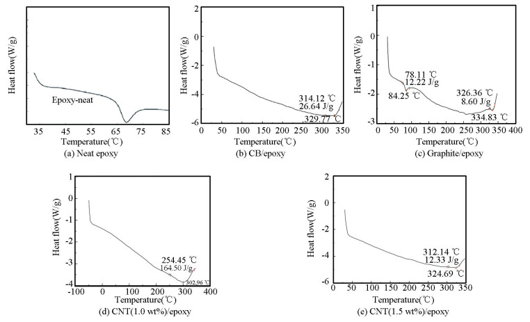
2.1.2 Glass transition temperatureDSC analysis was employed to calculate the glass transition temperature (Tg) of the nanocomposites, i.e., carbon-based nanofillers distribute in an epoxy matrix. In comparison with the neat epoxy, a change of Tg to higher temperature was detected in the composite material. Due to the reduced surface energy of the curing agent, epoxy is frequently adsorbed on the nanoparticles during the glass transition process in epoxy nanocomposites. This produces separation and variation of Tg at the interphase. The noticed alternation in Tg due to the inclusion of carbon fillers can change the structure of the cured epoxy by restricting the nucleophile-electrophile interaction during the cure reaction with a steric hindrance effect. This steric hindrance rises through the ratio surface-to-volume of the nanoparticle.
The DSC curves for neat epoxy, carbon black/epoxy, graphite/epoxy, and CNT/epoxy nanocom-posites with 1.0 and 1.5 wt% of CNT are shown in Fig. 3. The addition of different filler materials influences Tg of the matrix material. The steps in heat appeared around 300 ℃, which is similar to the glass transition of the amorphous filler. A thorough examination of the glass transition region for the composites as obtained from DSC measurement is presented in Table 2, in which Tg is denoted as the glass transition temperature (evaluated as the middle of the derived heat capacities prior to and subsequent to the glass transition). Tg, onset, and Tg, finish are defined as the intersection among the derived tangents prior to and subsequent to the glass transition correspondingly. From the figure, it is found that as compared with neat epoxy, the addition of fillers like carbon black, graphite and MWCNT lead to huge changes within the glass transition temperature of the nanocomposites, i.e., (65 ℃ to 300 ℃). Tg of carbon black specimen is 302℃, that of graphite specimen is 324℃ and MWCNT is 329℃. This glass transition in composites is determined by the free volume and the affinity between filler and polymer matrix. A polymer with a lower free volume and a higher affinity to filler shows higher Tg because the development of interphase between filler and matrix restricts polymer mobility. It is observed from the table that the infusion of 0.5 wt% MWCNT filler content has decreased Tg of nanocomposites by 25%. The decrease in Tg of the nanocomposite may be due to the existence of residual solvent that remains in the continuous phase even after the evaporation process. The residual solvent serves as an impurity that rises the thermal motions present in the molecular segments of the polymer and contributed in the reduction of Tg. When the filler leads to network disruption, it decreases the cross-link density and reduces the Tg[29].
|
Fig.3 DSC curves |
| Table 2 The glass transition temperature of composites |
2.2 Electrical Properties 2.2.1 Electrical conductivity
The electrical conductivity of the nanocomposite samples was calculated using an impedance analyzer (LCR Meter, Model IM 3370) in the range of 10 Hz to 10 MHz.The variation of AC electrical conductivity of the four types of polymeric composites is shown in Fig. 2(b).
Fig. 2(a) represents the electrical conductivity of epoxy-based composites as a function of frequency. The electrical conductivity graph presents a quasi-linear behavior which is usual for polymers. It can be noted that at low-frequency electrical conductivity is very small. With the increase in frequency, electrical conductivity also increases. The electrical conductivity of carbon-based nanocomposites depends on aspect ratio, types of filler, the weight percentage of filler, aggregation of filler, and surface functionalization[30]. The results shown in Fig. 2(b) indicate that graphite-based polymer composite with electrical conductivity of 4.6×10⁻⁵ as calculated using Eq. (1) shows good results as compared with the other three composites due to the percolation threshold, which is a conductive network built between the matrix and the delocalized π-electrons. It decreases the electrical resistance and increases conductivity. On the other hand, addition of CNT fillers to the epoxy matrix increases. With the addition of CNT content, the conductivity conquers the electrical percolation threshold and increases the number of conductive pathways. Due to the formation of more conductive pathways, higher current is transported through the material increasing electrical conductivity[31].
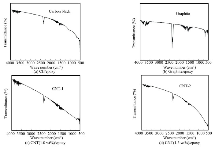
2.2.2 FTIR analysisFig. 4 shows FTIR spectra of CB/epoxy, graphite/epoxy, 1.0 wt% CNT/epoxy, 1.5 wt% CNT/epoxy, respectively. The FTIR spectra of all nanofillers are similar in all respects, i.e., the peaks are falling in the range of 2250-2500 cm-1, 1650-1850 cm-1 and below 1000 cm-1. It is inferred from the FTIR result that all the composite shows a peak near 2500 cm-1, which indicates the absorption band of C≡C in the materials, and also shows the asymmetrical vibrations of CO2[16]. The presence of carbon dioxide can be related to the porous nature of carbon-based nanofillers. The band in the region from 1650-1800 cm-1 is connected with the C=O stretching vibrations analogous to carbonyl and carboxyl groups, which is more prominent in the graphite-based fillers. Bands below 950 cm-1 have been allocated to out-of-plane screwing vibration of C-H groups in aromatic structures[27].
|
Fig.4 FTIR transmittance spectra |
2.3 Mechanical Properties 2.3.1 Tensile strength
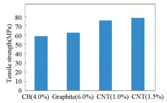
To facilitate the reinforcing consequence of fillers on the composites, tensile performance of composite containing various wt% of filler with epoxy matrix were studied. Based on the previous literature, nanoparticles with a high specific surface area increase the polymer matrix adhesion and lead to improvement in polymer's mechanical performance considerably.
The results as shown in Fig. 5 reveal that high tensile strength is obtained in the matrix which is reinforced with CNT than that of carbon black and graphite. This is due to the presence of a functional group, through which covalent bonds are formed and function as a junction between CNTs and polymer chains. Because the formation of bond stress transfer takes place between polymer and CNTs, it results in improvement of interfacial interaction[32]. Therefore, the functionalization of CNTs with good diffusion in the matrix is the main concern in the fabrication of nanocomposites[33]. After the application of load, the polymer chains shift towards the loading direction with the bonded CNTs and avoid slippage of the polymer chain. Therefore, additional tensile load needs to be applied before fracturing for deformation. The strong bonding between CNTs and epoxy due to the existence of functional groups regulates the strength of the main chain of the epoxy resin, which leads to an increase in Young's modulus of the nanocomposites. However, an increase in CNT content also increases tensile strength by about 6.0% with an extra 5 gm of filler content. Different tensile properties (like Young's modulus, ultimate tensile strength, and ultimate tensile strain) of epoxy matrix reinforced with different fillers are shown in Table 3.
|
Fig.5 Tensile strength v.s. different filler content of composites |
| Table 3 Tensile properties of epoxy reinforced with different fillers |
2.3.2 Microhardness
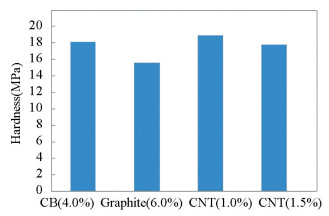
The variation of microhardness of the composites concerning the types of filler materials is shown in Fig. 6. High aspect ratio, high modulus, strength, and better formation network in CNT composite result in good interfacial bonding that gives an increase in hardness as compared with carbon black/epoxy and graphite/epoxy composites. The addition of nano-fillers into epoxy reduces the hardness due to weak interfacial bonding. High concentration of MWCNT filler in composite acting as defects as a result of stress concentration and therefore degrade the properties of the nanocomposite[34].
|
Fig.6 Hardness v.s. different filler content of composites |
2.4 Characterization
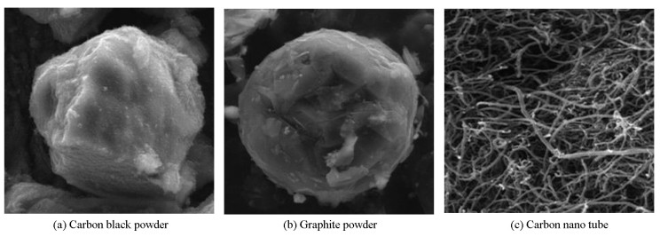
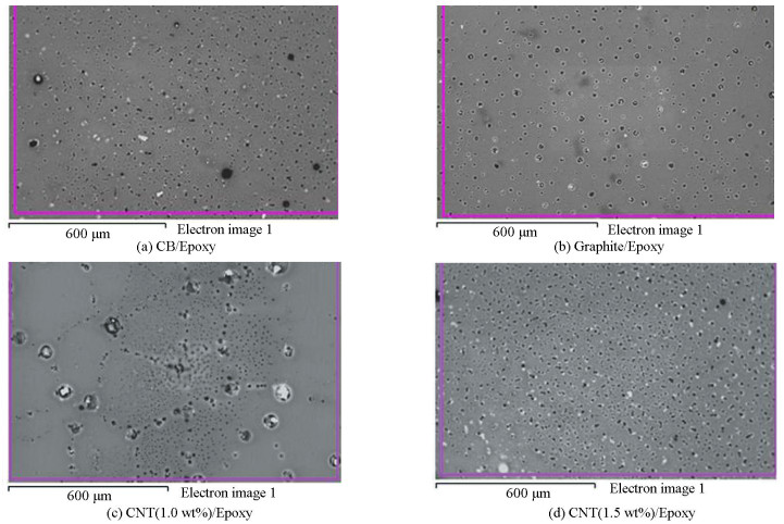
The microstructures of the pristine fillers were studied by using SEM in Fig. 7. The geometric parameters of all the composites containing different fillers used in this study were equivalent to those shown by SEM micrographs. Fig. 8 shows a poor dispersion of fillers (black and graphite) in the epoxy matrix because of bundling. The reason for the non-homogeneous distribution of fillers could be the extremely high viscosity which limited the movements of the fillers and prevent the proper distribution throughout the network. SEM micrographs of nanocomposites (CNT/Epoxy) fabricated with sonication and shear mixing are given in Fig. 8(c)-(d). According to the figure, a relatively homogeneous distribution of CNTs in the matrix was achieved as a result of sonication and shear mixing. Dispersing CNTs into the matrix helped the de-bundling, which leads to more uniform dispersion. Fig. 8(c) shows a more robust 3D interconnected network with clear and well-defined borders which indicate a strong interfacial bond between the carbon atoms. According to Fig. 8(d), addition of fillers in the matrix results in a more homogeneous dispersion. Good distribution of CNTs increases the mechanical properties of nanocomposites. Due to good distribution, more filler surface area is available which restricts stress concentrations as well as slippage when the load is applied[35]. Good interfacial bonding between nanotube and matrix also enhances the hardness. The presence of agglomeration in graphite and carbon black composite may be the cause for higher levels of loading of filler compared with MWCNT for acquiring the required levels of conductivity.
|
Fig.7 SEM micrographs of carbon black powder, graphite powder, and carbon nano tube |
|
Fig.8 SEM micrographs of CB/epoxy, graphite/epoxy, CNT(1.0 wt%)/epoxy, and CNT(1.5 wt%)/epoxy |
3 Practical Implications
The usage of composite materials has progressed through several stages since 1960. In terms of ease of reliability, biodegradability, higher physical properties, and manufacturing, composite materials are the primary substitution of traditional engineering materials. The potential use of composites in different areas has drawn the attention of researchers to build new materials to serve domestic and industrial needs. The applications of carbon-based materials in the global energy prospect is a subject that has fascinated considerable awareness in recent times. The applications include material science, aerospace, defense components, household, energy storage applications (fuel cell, capacitors, lithium-ion battery), automobile, etc.[5]
CNT-based filler exhibits better thermal, electrical, and mechanical properties. But their exorbitant price is the biggest barrier to extensive use. Some household applications like footwear and sporting goods require low cost and simple fabrication method but must have properties like high strength, lightweight, and durability. Although CNT/Epoxy and graphite/epoxy possess high strength due to high cost, CB/epoxy composite may be the choice for the above applications with optimum percentage of filler content.
Due to rapid depletion of fossil fuel reservoir, energy crunch of the 21st Century is a theme that has been discussed comprehensively by the scientists. Fossil fuels are generally non-renewable and not environmentally friendly. Electrochemical devices such as capacitors and fuel cells are energy storage devices. The main component of the fuel cells is the proton-exchange membranes (PEMS) which affords an ionic pathway for the transport of protons and restrain the mixing of reactant gases. The most studied solid polymer Nafion membrane limits their additional application due to high permeability, high cost, and low glass transition temperature[36]. To overcome the limitations of excellent mechanical properties, low cost, high electrical potential, a compression-molded graphite/epoxy composite may be used in bipolar plate.
On the other hand, CNT shows excellent thermal, electrical, and mechanical properties with epoxy matrix. Therefore, it can be used in automotive and structural applications such as radar-absorbing material, aerospace, body armor in defense, EMI shielding, and many more.
4 ConclusionsDifferent filler materials such as allotropes of nanocarbon are integrated with epoxy matrix to fabricate different multiscale nanocomposites. Tensile, electrical, and mechanical properties of various multiscale nanocomposites were evaluated and correlated with the observed microstructural image obtained from SEM. The important findings are as follows:
1) The tensile strength and hardness are improved by 25% and 33% respectively in CNT reinforced composite material as compared with carbon black and graphite-reinforced composites;
2) A modest increment in tensile strength was observed with an extra 5 gm of filler content;
3) Thermal experiments demonstrate that the addition of MWCNT filler increases the thermal conductivity, but the glass transition temperature has reduced due to the addition of filler. This may be due to the presence of a residual solvent;
4) From LCR Meter, it was found that graphite-based polymer composite shows good electrical conductors as compared with the other three multi-scale nanocomposites due to delocalization of Π-electrons in carbon atoms of graphite;
5) SEM analysis shows the good distribution of fillers in an epoxy matrix and no formation of agglomerates. Fig. 8(c) shows a more robust 3D interconnected network with clear and well-defined borders which indicate a strong interfacial bond between the carbon atoms.
| [1] |
Ansari F, Sobhani A, Salavati-Niasari M. PbTiO3/PbFe12O19 nanocomposites: green synthesis through an eco-friendly approach. Composites Part B: Engineering, 2016, 85: 170-175. DOI:10.1016/j.compositesb.2015.09.027 (  0) 0) |
| [2] |
Rahman M, Ramakrishna S, Prakash J R S, et al. Machinability study of carbon fiber reinforced composite. Journal of Materials Processing Technology, 1999, 89-90: 292-297. DOI:10.1016/S0924-0136(99)00040-0 (  0) 0) |
| [3] |
Zhang Y G, Yin Q Z. Carbon and other light element contents in the Earth's core based on first-principles molecular dynamics. PNAS, 2012, 109(48): 19579-19583. DOI:10.1073/pnas.1203826109 (  0) 0) |
| [4] |
Allègre C J, Poirier J P, Humler E, et al. The chemical composition of the Earth. Earth and Planetary Science Letters, 1995, 134(3-4): 515-526. DOI:10.1016/0012-821X(95)00123-T (  0) 0) |
| [5] |
Nasir S, Hussein M, Zainal Z, et al. Carbon-based nanomaterials/allotropes: aglimpse of their synthesis, properties and some applications. Materials, 2018, 11(2): 295. DOI:10.3390/ma11020295 (  0) 0) |
| [6] |
Montazeri A, Javadpour J, Khavandi A, et al. Mechanical properties of multi-walled carbon nanotube/epoxy composites. Materials & Design, 2010, 31(9): 4202-4208. DOI:10.1016/j.matdes.2010.04.018 (  0) 0) |
| [7] |
Zhou Y X, Pervin F, Rangari V K, et al. Fabrication and evaluation of carbon nano fiber-filled carbon/epoxy composite. Materials Science and Engineering: A, 2006, 426(1-2): 221-228. DOI:10.1016/j.msea.2006.04.031 (  0) 0) |
| [8] |
Montazeri A, Khavandi A, Javadpour J, et al. Viscoelastic properties of multi-walled carbon nanotube/epoxy composites using two different curing cycles. Materials & Design, 2010, 31(7): 3383-3388. DOI:10.1016/j.matdes.2010.01.051 (  0) 0) |
| [9] |
Yeh M K, Tai N H, Liu J H. Mechanical behavior of phenolic-based composites reinforced with multi-walled carbon nanotubes. Carbon, 2006, 44(1): 1-9. DOI:10.1016/j.carbon.2005.07.005 (  0) 0) |
| [10] |
Li Z, Gao Y, Moon K S, et al. Automatic quantification of filler dispersion in polymer composites. Polymer, 2012, 53(7): 1571-1580. DOI:10.1016/j.polymer.2012.01.048 (  0) 0) |
| [11] |
Wong E W, Sheehan P E. Nanobeam mechanics: elasticity, strength, and toughness of nanorods and nanotubes. Science, 1997, 277(5334): 1971-1975. DOI:10.1126/science.277.5334.1971 (  0) 0) |
| [12] |
Deep N, Mishra P. Evaluation of mechanical properties of functionalized carbon nanotube reinforced PMMA polymer nanocomposite. Karbala International Journal of Modern Science, 2018, 4(2): 207-215. DOI:10.1016/j.kijoms.2018.02.001 (  0) 0) |
| [13] |
Kausar A, Rafique I, Muhammad B. Review of applications of polymer/carbon Nanotubes and epoxy/CNT composites. Polymer-Plastics Technology and Engineering, 2016, 55(11): 1167-1191. DOI:10.1080/03602559.2016.1163588 (  0) 0) |
| [14] |
Yang K, Gu M Y, Guo Y P, et al. Effects of carbon nanotube functionalization on the mechanical and thermal properties of epoxy composites. Carbon, 2009, 47(7): 1723-1737. DOI:10.1016/j.carbon.2009.02.029 (  0) 0) |
| [15] |
Kassim S A E, Achour M E, Costa L C, et al. Modelling the DC electrical conductivity of polymer/carbon black composites. Journal of Electrostatics, 2014, 72(3): 187-191. DOI:10.1016/j.elstat.2014.02.002 (  0) 0) |
| [16] |
Barekat M, Razavi R S, Sharifianjazi F. Synthesis and the surface resistivity of carbon black pigment on black silicone thermal control coating. Synthesis and Reactivity in Inorganic, Metal-Organic, and Nano-Metal Chemistry, 2015, 45(4): 502-506. DOI:10.1080/15533174.2013.809751 (  0) 0) |
| [17] |
Sreekumar P A, Joseph K, Unnikrishnan G, et al. A comparative study on mechanical properties of sisal-leaf fibre-reinforced polyester composites prepared by resin transfer and compression moulding techniques. Composites Science and Technology, 2007, 67(3-4): 453-461. DOI:10.1016/j.compscitech.2006.08.025 (  0) 0) |
| [18] |
Andrews R, Jacques D, Qian D L, et al. Multiwall carbon nanotubes: synthesis and application. Accounts of Chemical Research, 2002, 35(12): 1008-1017. DOI:10.1021/ar010151m (  0) 0) |
| [19] |
Tjong S C. Polymer nanocomposite bipolar plates reinforced with carbon nanotubes and graphite nanosheets. Energy and Environmental Science, 2011, 4: 605-626. DOI:10.1039/C0EE00689k (  0) 0) |
| [20] |
Banks-Sills L, Shiber D G, Fourman V, et al. Experimental determination of mechanical properties of PMMA reinforced with functionalized CNTs. Composites Part B: Engineering, 2016, 95: 335-345. DOI:10.1016/j.compositesb.2016.04.015 (  0) 0) |
| [21] |
Arash B, Park H S, Rabczuk T. Mechanical properties of carbon nanotube reinforced polymer nanocomposites: a coarse-grained model. Composites Part B: Engineering, 2015(80): 92-100. DOI:10.1016/j.compositesb.2015.05.038 (  0) 0) |
| [22] |
Dresselhaus M S, Jorio A, Saito R. Characterizing graphene, graphite, and carbon nanotubes by Raman spectroscopy. Annual Review of Condensed Matter Physics, 2010, 1: 89-108. DOI:10.1146/annurev-conmatphys-070909-103919 (  0) 0) |
| [23] |
Sengupta S, Bhattacharya M, Bandyopadhyay S, et al. A review on the mechanical and electrical properties of graphite and modified graphite reinforced polymer composites. Progress in Polymer Science, 2011, 36(5): 638-670. DOI:10.1016/j.progpolymsci.2010.11.003 (  0) 0) |
| [24] |
Yin M, Koutsky J A, Barr T L, et al. Characterization of carbon microfibers as reinforcement for epoxy resins. Chemistry of Materials, 1993, 5(7): 1024-1031. DOI:10.1021/cm00031a025 (  0) 0) |
| [25] |
Yasmin A, Daniel I M. Mechanical and thermal properties of graphite platelet/epoxy composites. Polymer, 2004, 45(24): 8211-8219. DOI:10.1016/j.polymer.2004.09.054 (  0) 0) |
| [26] |
Chen J J, Gao X H, Song W Y. Effect of various carbon nanofillers and different filler aspect ratios on the thermal conductivity of epoxy matrix nanocomposites. Results in Physics, 2019, 15: 102-771. DOI:10.1016/j.rinp.2019.102771 (  0) 0) |
| [27] |
Akcin Y, Karakaya S, Soykasap O. Electrical, thermal and mechanical properties of CNT treated prepreg CFRP composites. Materials Sciences and Applications, 2016, 7(9): 465-483. DOI:10.4236/msa.2016.79041 (  0) 0) |
| [28] |
Fang Z N, Li M, Wang S K, et al. Through-thickness thermal conductivity enhancement of carbon fiber composite laminate by filler network. International Journal of Heat and Mass Transfer, 2019, 137: 1103-1111. DOI:10.1016/j.ijheatmasstransfer.2019.04.007 (  0) 0) |
| [29] |
Allaoui A, El Bounia N. How carbon nanotubes affect the cure kinetics and glass transition temperature of their epoxy composites? - A review. Express Polymer Letters, 2009, 3(9): 588-594. DOI:10.3144/expresspolymlett.2009.73 (  0) 0) |
| [30] |
Moosa A A, Ramazani A A S, Ibrahim M N, et al. Mechanical and electrical properties of graphene nanoplates and carbon-nanotubes hybrid epoxy nanocomposites. American Journal of Materials Science, 2016, 6(16): 157-165. DOI:10.5923/j.materials.20160606.03 (  0) 0) |
| [31] |
Balakrishnan A, Saha M C. Tensile fracture and thermal conductivity characterization of toughened epoxy/CNT nanocomposites. Materials Science and Engineering: A, 2011, 528(3): 906-913. DOI:10.1016/j.msea.2010.09.064 (  0) 0) |
| [32] |
Yang S Y, Lin W N, Huang Y L, et al. Synergetic effects of graphene platelets and carbon nanotubes on the mechanical and thermal properties of epoxy composites. Carbon, 2011, 49: 793-803. DOI:10.1016/j.carbon.2010.10.014 (  0) 0) |
| [33] |
Tariq F, Shifa M, Baloch R A. Mechanical and thermal properties of multi-scale carbon nanotubes-carbon fiber-epoxy composite. Arabian Journal for Science and Engineering, 2018, 43: 5937-5948. DOI:10.1007/s13369-018-3091-8 (  0) 0) |
| [34] |
Inam F, Wong D W Y, Kuwata M, et al. Multiscale hybrid micro-nanocomposites based on carbon nanotubes and carbon fibers. Journal of Nanomaterials, 2010, 2010: 1-12. DOI:10.1155/2010/453420 (  0) 0) |
| [35] |
Li M, Gu Y Z, Liu Y N, et al. Interfacial improvement of carbon fiber/epoxy composites using a simple process for depositing commercially functionalized carbon nanotubes on the fibers. Carbon, 2013, 52: 109-121. DOI:10.1016/j.carbon.2012.09.011 (  0) 0) |
| [36] |
Adzic R R, Zhang J, Sasaki K, et al. Uribe, platinum monolayer fuel cell electrocatalysts. Topics in Catalysis, 2007, 46: 249-262. DOI:10.1007/s11244-007-9003-x (  0) 0) |
 2022, Vol. 29


