2. Fujian (Quanzhou)-HIT Research Institute of Engineering and Technology, Quanzhou 362000, Fujian, China;
3. School of Astronautics, Harbin Institute of Technology, Harbin 150001, China
The past several decades has witnessed the burgeoning development in the spacecraft attitude control system on account of its vital role in applications like spacecraft formation, satellite surveillance and pointing, etc. Hence, tremendous research works on attitude controller synthesis spring up[1-2]. With the deepening of the research, it has become a knowledge that there exist two-fold challenges in the spacecraft attitude control[3]: first, all the parameterizations utilized to depict the attitude will suffer from singularities or ambiguities; second, no continuous time-variant controller can stabilize all the attitudes on SO(3). To confront these challenges, some researchers develop various geometric control schemes with theaid of the exponential coordinates, Morse function, and pseudo-Morse function, which can achieve the continuous almost global stability[4] or discontinuous global stability[5]. Additionally, some quaternion-based global stabilizing control schemes also emerge for the attitude error tracking system recently[6].
As the convergence rate is a vital performance criterion in synthesizing the attitude controller, many fruitful finite-time controllers are developed[7-8]. However, the settling time in these finite-time results depends on the initial condition which prohibits their applications if the designer has no prior knowledge of the initial states. To remove the limitation of the finite-time algorithm, some fixed-time attitude control schemes are developed by using the sliding mode approach[9-10] and backstepping technique[11], in which the upper bound can be estimated by the control parameter. But the obtained settling time is always too conservative[12]. Moreover, it should also be stressed that two problems will be encountered in the aforesaid finite/fixed-time strategies. The first one is that the transient and steady-state performance cannot be preset in advance, i.e., the satisfactory system performance can only be achieved through repeated alteration of the design parameters tediously. The second one is that the constructed controllers are mainly based on the fractional-order state or output feedback and thus involve a considerable computational burden, in which the settling time cannot be specified in advance.
Fortunately, the prescribed performance control (PPC) technique makes it possible to tackle the first problem, which characterizes the transient and steady-state performance quantitatively by a well-designed performance function[13-14]. In virtue of this transform approach, Ref. [15] proposes a geometric sliding mode control scheme for the spacecraft attitude tracking with the transient and steady-state performance constraint. Ref. [16] extends this method to consider the actuator faults and input saturation. However, since exponential performance functions are adopted in these control schemes, the system can only be driven to the pre-assigned steady-state performance boundary as the time tends to infinity. To conquer this defect, some researchers address the finite-time PPC consensus problem by combining sliding mode control and PPC technique[17-18]. But the second problem mentioned above is still not solved, i.e., the convergence time can only be obtained by a conservative estimation using the initial condition and control parameters. To overcome this drawback, Ref. [19] devises a novel appointed-time prescribed performance controller, which can ensure the concerned error converges into the pre-assigned steady-state performance boundary within the prescribed time. But the acquisition of the controller requires online calculation of a complex differential equation in real time, which will consume a lot of computation resource. To solve this issue, some researchers are devoted to devising simple appointed-time performance functions[20-22].
It is worth noting that to enhance the robustness to the unexpected model uncertainties and external disturbances, the adaptive technique is adopted in some of the foregoing studies. However, the optimal control performance cannot be achieved simultaneously. Although optimal control is an effective way to ensure the tracking performance to be optimized, the acquisition of optimal solution requires solving the Hamilton-Jacobi-Bellman (HJB) equation. It is usually impossible to acquire solution of this equation directly due to computational constraints. To overcome this shortcoming, some researchers turn to several approximation approaches such as dynamic programming, Q-learning, and adaptive dynamic programming (ADP) to seek the most accurate possible solutions. As a reinforcement learning approach, the ADP is utilized to tackle the optimal control problem extensively[24]. In Refs. [25-26], the AC architecture is applied to approximate the control input and the value function, and all sorts of reinforcement-learning-based schemes are devised by generalizing policy iteration algorithms. The actor neural network is employed to approximate unknown nonlinearity or the dynamics variation during the operation and compensate the nonlinear effects to improve the tracking performance[27-28].
Inspired by the above observations, we are devoted to constructing an adaptive control algorithm using the actor-critic NN architecture for the attitude tracking problem of the rigid spacecraft subjected to the external disturbances in this paper. The main contributions are summarized as below: 1) Different from conversional adaptive control schemes based on NN or fuzzy logic[20, 29-30], the proposed adaptive attitude tracking control scheme improves the approximation performance of the actor NN by introducing a critic signal. To be specific, a critic function is employed to measure the system performance and adjust the weights of the actor NN to improve the approximation performance in the critic part. In the actor part, the actor NN is utilized to approximate the complex nonlinearities and produce the feedforward compensation term. 2) Different from the current prescribed performance control schemes[13-16], the convergence time can also be characterized in advance by using a novel appointed-time performance. 3) An adaptive robust term is constructed to tackle the disturbances and the reconstruction errors resulting from the actor NN and critic NN without the knowledge of the bounds information of disturbance, the ideal weights of actor NN, and critic NN.
The notions in this paper are as follows. R∈SO(3) is the spacecraft attitude with respect to the inertial frame, ω∈ R3 is the angular velocity expressed in its body-fixed frame, J∈R3×3 is the inertia matrix, τ∈R3 is the control torque, and τd∈R3 is the unknown external disturbance. The hat map
To avoid breaking the topology properties of the attitude configuration space during the controller design, it is considered that the attitude dynamic model of the spacecraft on the tangent bundle TSO(3) takes the following form:
| $ \left\{\begin{array}{l} \dot{\boldsymbol{R}}=\boldsymbol{R} \hat{\boldsymbol{\omega}} \\ \boldsymbol{J} \dot{\boldsymbol{\omega}}=-\boldsymbol{\omega} \times \boldsymbol{J} \boldsymbol{\omega}+\boldsymbol{\tau}+\boldsymbol{\tau}_d \end{array}\right. $ | (1) |
Assumption 1 The external disturbance τd is bounded by ||τd||≤δd, where δd is a positive constant.
Property 1 The inertia matrix J is symmetric and positive definite such that λmin(J)I3≤J≤λmax(J)I3, where λmin(J) and λmax(J) are the minimum and maximum eigenvalue of J, respectively.
Remark 1 Assumption 1 implies that the controller to be designed is required to be robust to the external disturbance bounded by δd. As is known, the spacecraft is always subjected to external disturbances whose exact bound is difficult to be found. In effect, the system often has a toleration constraint on the bound of external disturbance, which means that if the external disturbance does not exceed the pre-specified tolerated bound, the control system will work stably and is ensured to satisfy the performance requirements. Thus, for robustness consideration, it is meaningful to assume the external disturbance is bounded, which means that under the specified bound of tolerated external disturbance, the system with our controller will have the robust performance.
The control aim of this work is to derive a reinforcing-learning-based control torque τ such that the actual attitude of the spacecraft track the reference trajectory Rr with the pre-assigned convergence time and steady-state performance, which is generated following the kinematic equation below:
| $ \dot{\boldsymbol{R}}_r=\boldsymbol{R}_r \hat{\boldsymbol{\omega}}_r $ |
To conquer the difficulty constructing attitude controller directly on SO(3) arising from its non-Euclidean property, the smooth positive attitude error function is borrowed from Ref. [3] to measure the error between the actual spacecraft's attitude and the reference one RrTR, given as below:
| $ \psi=2-\sqrt{1+\operatorname{trace}\left(\boldsymbol{R}_r^{\mathrm{T}} \boldsymbol{R}\right)} $ | (2) |
Its corresponding attitude and angular velocity error vector eo and eω are given as
| $ \boldsymbol{e}_o=\frac{\left(\boldsymbol{R}_r^{\mathrm{T}} \boldsymbol{R}-\boldsymbol{R}^{\mathrm{T}} \boldsymbol{R}_r\right)^{\vee}}{2 \sqrt{1+\operatorname{trace}\left(\boldsymbol{R}_r^{\mathrm{T}} \boldsymbol{R}\right)}} $ |
| $ \boldsymbol{e}_\omega=\boldsymbol{\omega}-\boldsymbol{R}_e^{\mathrm{T}} \boldsymbol{\omega}_d $ |
where the map (·)∨: SO(3)→R3 is the inverse of the hat map such that
| $ \left\{ \begin{array}{l} \dot \psi = \mathit{\boldsymbol{e}}_\mathit{o}^{\rm{T}}{\mathit{\boldsymbol{e}}_\mathit{\omega }}\\ {{\mathit{\boldsymbol{\dot e}}}_o} = {E_\mathit{\omega }}{\mathit{\boldsymbol{e}}_\mathit{\omega }}\\ \mathit{\boldsymbol{J\dot e_\mathit{\omega } = - \omega }} \times \mathit{\boldsymbol{J}}\mathit{\omega } + \mathit{\boldsymbol{\tau + J}}{{\mathit{\boldsymbol{\hat e}}}_\mathit{\omega }}{\mathit{\boldsymbol{R}}^{\rm{T}}}{\mathit{\boldsymbol{R}}_r}{\mathit{\boldsymbol{\omega }}_r} - \\ \;\;\;\;\;\;\mathit{\boldsymbol{J}}{\mathit{\boldsymbol{R}}^{\rm{T}}}{\mathit{\boldsymbol{R}}_r}{{\mathit{\boldsymbol{\dot \omega }}}_r} + {\mathit{\boldsymbol{\tau }}_d} \end{array} \right. $ | (3) |
where
| $ \boldsymbol{E}_\omega=\frac{\operatorname{trace}\left(\boldsymbol{R}^{\mathrm{T}} \boldsymbol{R}_r\right) \boldsymbol{I}_3-\boldsymbol{R}^{\mathrm{T}} \boldsymbol{R}_r+2 \boldsymbol{e}_o \boldsymbol{e}_o^{\mathrm{T}}}{2 \sqrt{1+\operatorname{trace}\left(\boldsymbol{R}_r^{\mathrm{T}} \boldsymbol{R}\right)}} $ | (4) |
Remark 2 It follows from Rodrigues' formula that for any Re=RrTR∈SO(3) an x∈R3 always exists with ||x||≤π such that
| $ \boldsymbol{R}_e=\boldsymbol{I}_3+\frac{\sin (\|\boldsymbol{x}\|)}{\|\boldsymbol{x}\|} \hat{\boldsymbol{x}}+\frac{1-\cos (\|\boldsymbol{x}\|)}{\|\boldsymbol{x}\|^2} \hat{\boldsymbol{x}}^2 $ | (5) |
Substituting Eq. (5) into Eqs. (2) and (3) yields
| $ \psi=4 \sin ^2\left(\frac{\|\boldsymbol{x}\|}{4}\right) \leqslant 2 $ |
| $ \mathit{\boldsymbol{e}}_o=\sin \left(\frac{\|\boldsymbol{x}\|}{2}\right) \frac{\boldsymbol{x}}{\|\boldsymbol{x}\|} $ |
| $ \boldsymbol{E}_\omega=\frac{1}{2}\left(\cos \left(\frac{\|\boldsymbol{x}\|}{2}\right) \boldsymbol{I}_3+\sin \left(\frac{\|\boldsymbol{x}\|}{2}\right) \frac{\hat{\boldsymbol{x}}}{\|\boldsymbol{x}\|}\right) $ |
It follows from the above expression that the eigenvalues of EωTEω are 1/4, 1/4 and cos2(||x||/2)/4, i.e., the matrix Eω is invertible for all ||x||≤π. Furthermore, ||eo|| is monotonically increasing on the interval [0, π], and satisfies ||eo||=sin (||x||/2)≤1.
Lemma 1[22] The inequality -tanhT(v0/εv)·v0≤-||v0||+mkbεv always holds for any vector and constant v0∈Rm, εv>0, where kb is a constant such that kb=e-(kb+1), i.e., kb=0.2785.
Lemma 2 Given arbitrary unknown continuous nonlinear function f(Z): Rq→R over a compact set ΩZ⊂Rq, the following radial basis function neural network (RBF NN) can be utilized to approximate to any accuracy:
| $ f(Z)=\boldsymbol{W}^{* \mathrm{~T}} h(\boldsymbol{Z})+\varepsilon, \quad \forall Z \in \Omega_Z $ | (6) |
where Z∈Rq is the NN input vector, W*∈Rs is an unknown optimal constant weight vector with s>1 being the NN node number, ε∈R is the functional approximation error under the ideal NN weight and is bounded by |ε|≤ε < ∞ with ε as an unknown constant. h(Z)=[h1(Z), h2(Z), …, hs(Z)]T∈Rs with hi(Z) being the Gaussian function is shown as below:
| $ \boldsymbol{h}_i(Z)=\exp \left[\frac{-\left(Z-\mu_i\right)^{\mathrm{T}}\left(Z-\mu_i\right)}{\sigma^2}\right] $ |
where i=1, 2, …, s, μi is the center for the ith input element of the NN, and σ is the variance. Then, an approximation of f(Z) can be expressed as
| $ \boldsymbol{W}^*:=\arg \min _{W \in \bf{R}^{\rm{S}}}\left\{\sup\limits_{Z \in \Omega_Z}\left|f(Z)-\boldsymbol{W}^{\mathrm{T}} \boldsymbol{h}(Z)\right|\right\} $ |
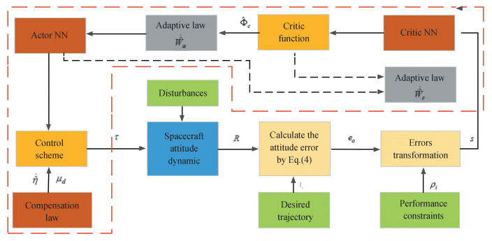
In this part, the attitude tracking control strategy will be derived by utilizing the actor-critic learning algorithm. To make the tracking error meet the assigned transient and steady-state performance, a novel error transformation technique is introduced to convert the error dynamic system with performance constraint into the equivalent unconstraint one. Then, an actor neural network is utilized to approximate the unknown nonlinear term based on the information received from the control environment. A critic function is constructed to supervise the tracking performance and tune the weights of the AC neural networks. Based on the output information of the actor NN, an adaptive controller is designed to reduce the effect of the NN reconstruction errors. The diagram of actor-critic learning control is shown in Fig. 1.
|
Fig.1 Block diagram of the spacecraft attitude system under the proposed control architecture |
2.1 Prescribed Performance Function and Error Transformation
To guarantee the tracking error possesses the specified performance, it is expected that the attitude tracking error evolves inside the set
| $ -\underline{\delta}_i \rho_i(t)<e_{o, i}<\bar{\delta}_i \rho_i(t), i=1, 2, 3, \forall t \geqslant 0 $ | (7) |
where 0 < δi, δi≤1, ρi(t) are the performance functions satisfying
| $ \rho_i(t)= \begin{cases}\rho_{i, 0}+\sum\limits_{k=2}^4 \rho_{i, k} t^k, t<t_f \\ \rho_{i, \infty}, \;\;\;\;\;\;\;\;\;\;\;\;\;\;\; t \geqslant t_f\end{cases} $ |
where tf, ρi, 0, and ρi, ∞ are the convergence time to be assigned by the designer and steady-state value of ρi, respectively. The parameters ρi, k, k=2, 3, 4 are determined by
| $ \left[\begin{array}{l} \rho_{i, 2} \\ \rho_{i, 3} \\ \rho_{i, 4} \end{array}\right]=\left[\begin{array}{lll} t_f^2 & t_f^3 & t_f^4 \\ 2 t_f & 3 t_f^2 & 4 t_f^3 \\ 2 & 6 t_f & 12 t_f^2 \end{array}\right]^{-1}\left[\begin{array}{c} \rho_{i, \infty}-\rho_{i, 0} \\ 0 \\ 0 \end{array}\right] $ |
In order to solve the error stabilization issue with the prescribed performance constraint, the following constraint-free mapping T(·)∶(-δi, δi)→(-∞, +∞) is introduced to convert it into an equivalent unconstrained one:
| $ \xi_{o, i}(t)=\frac{1}{2 \vartheta_i} T_i\left(\frac{e_{o, i}(t)}{\rho_i(t)}\right)=\frac{1}{2 \vartheta_i} \ln \left(\frac{\bar{\delta}_i \underline{\delta}_i+\bar{\delta}_i e_{o, i} / \rho_i}{\bar{\delta}_i \underline{\delta}_i-\bar{\delta}_i e_{o, i} / \rho_i}\right) $ |
It is not difficult to verify that the map Ti(·) is a smooth and strictly increasing bijective mapping, and eo, i=ρiTi-1(2ϑiξo, i). By simple calculation, there is
Calculating the derivative of the transformed error ξo and applying Eqs. (3) yields
| $ \dot{\boldsymbol{\xi}}_o=\boldsymbol{E}_o\left(\dot{\boldsymbol{e}}_o-\boldsymbol{N}_o \boldsymbol{e}_o\right)=\boldsymbol{E}_o\left(\boldsymbol{E}_\omega \boldsymbol{e}_\omega-\boldsymbol{N}_o \boldsymbol{e}_o\right) $ |
where No=diag
| $ \boldsymbol{E}_{o, i}=\frac{1}{2 {\vartheta}_i \rho_i}\left(\frac{1}{{\underline \delta _i}+e_{o, i} / \rho_i}+\frac{1}{\bar{\delta}_i-e_{o, i} / \rho_i}\right) $ |
For the convenience of controller design, a novel error is introduced:
| $ \boldsymbol{s}=\dot{\boldsymbol{\xi}}_o+\lambda \boldsymbol{\xi}_o $ |
The time derivative of s is given as
| $ \begin{aligned} \dot{\boldsymbol{S}}= & \left(\dot{\boldsymbol{E}}_o+\boldsymbol{\lambda} \boldsymbol{E}_o\right)\left(\dot{\boldsymbol{e}}_o-\boldsymbol{N}_o \boldsymbol{e}_o\right)+\boldsymbol{E}_o\left(\dot{\boldsymbol{E}}_\omega \boldsymbol{e}_\omega+\right. \\ & \left.\boldsymbol{E}_\omega \dot{\boldsymbol{e}}_\omega-\dot{\boldsymbol{N}}_o \boldsymbol{e}_o-\boldsymbol{N}_o \dot{\boldsymbol{e}}_o\right)= \\ & \boldsymbol{E}_o\left(\boldsymbol{E}_\omega \boldsymbol{J}^{-1} \boldsymbol{\tau}+\boldsymbol{f}+\boldsymbol{E}_\omega \boldsymbol{J}^{-1} \boldsymbol{\tau}_d\right) \end{aligned} $ | (8) |
where
| $ \begin{aligned} \boldsymbol{f}= & \dot{\boldsymbol{E}}_\omega \boldsymbol{e}_\omega+\boldsymbol{E}_\omega\left(-J^{-1} \hat{\boldsymbol{\omega}} J \boldsymbol{\omega}+\hat{\boldsymbol{e}}_\omega \boldsymbol{R}^{\mathrm{T}} \boldsymbol{R}_d \boldsymbol{\omega}_d-\right. \\ & \left.\boldsymbol{R}^{\mathrm{T}} \boldsymbol{R}_d \dot{\boldsymbol{\omega}}_d\right)-\dot{\boldsymbol{N}}_o \boldsymbol{e}_o-\boldsymbol{N}_o \boldsymbol{E}_\omega \boldsymbol{e}_\omega+\left(\boldsymbol{E}_o^{-1} \dot{\boldsymbol{E}}_o+\right. \\ & \left.\lambda \boldsymbol{I}_3\right)\left(\boldsymbol{E}_\omega \boldsymbol{e}_\omega-\boldsymbol{N}_o \boldsymbol{e}_o\right) \end{aligned} $ |
As f is a complex nonlinear term, it is difficult to compensate this term directly by feedforward. To this end, actor-NN is utilized to approximate it, which takes the following form:
| $ \boldsymbol{f}=\boldsymbol{W}_a^{\mathrm{T}} \boldsymbol{\sigma}_a\left(\boldsymbol{V}_a \overline{\boldsymbol{x}}\right)+\boldsymbol{\varepsilon}_a(\overline{\boldsymbol{x}}) $ | (9) |
where Wa∈RNl×3 is the optimal weight matrix, σa is the basis function vector, x=[eoT, ωT, ωdT, eωT]T is the input vector, Va∈RNl×12 is the weight matrix between the input layer and the output layer which is chosen as a constant matrix, the approximation error εa(x) is bounded by ||εa(x)|| < εa.
Inspired by Ref. [23], the following critic function is introduced to evaluate the tracking performance:
| $ \mathit{\boldsymbol{ \boldsymbol{\varPhi} }}_c=\boldsymbol{E}_o^{\mathrm{T}} \mathit{\boldsymbol{ \boldsymbol{\varPhi} }}+\left\|\boldsymbol{E}_o^{\mathrm{T}} \mathit{\boldsymbol{ \boldsymbol{\varPhi} }}\right\| \boldsymbol{W}_c^{\mathrm{T}} \boldsymbol{\sigma}_c\left(\boldsymbol{V}_c \overline{\boldsymbol{x}}\right) $ |
where the first term ΕoTΦ is the primary critic signal vector, Φ=[Φ1, Φ2, Φ3]T with Φi=
| $ \hat{\mathit{\boldsymbol{ \boldsymbol{\varPhi} }}}_c=\boldsymbol{E}_o^{\mathrm{T}} \mathit{\boldsymbol{ \boldsymbol{\varPhi} }}+\left\|\boldsymbol{E}_o^{\mathrm{T}} \mathit{\boldsymbol{ \boldsymbol{\varPhi} }}\right\| \hat{\boldsymbol{W}}_c^{\mathrm{T}} \boldsymbol{\sigma}_c $ | (10) |
where
Before presenting the controller, the following assumption and lemma are given, which will be utilized in the stability proof.
Assumption 2 The ideal weights of the actor NN Wa and critic NN Wc are upper bounded by ||Wa||≤Wa* and ||Wc||≤Wc*, where Wa* and Wc* are unknown positive constants.
Remark 3 As functions, the actor NN and critic NN to be approximated are bounded and the basic functions σa, σc are also bounded. The corresponding ideal weights should also be bounded. Thus, Assumption 2 is reasonable.
Lemma 3 Function F1 is defined as
| $ \begin{aligned} & \boldsymbol{F}_1=\left\|\boldsymbol{E}_o^{\mathrm{T}} \mathit{\boldsymbol{ \boldsymbol{\varPhi} }}\right\| \operatorname{trace}\left(\boldsymbol{W}_c^{\mathrm{T}} \boldsymbol{\sigma}_c \boldsymbol{\sigma}_a^{\mathrm{T}} \hat{\boldsymbol{W}}_a-\right. \\ & \\ & \left.\quad \boldsymbol{W}_a^{\mathrm{T}} \boldsymbol{\sigma}_a \boldsymbol{\sigma}_c^{\mathrm{T}} \hat{\boldsymbol{W}}_c\right)+\mathit{\boldsymbol{ \boldsymbol{\varPhi} }}^{\mathrm{T}} \boldsymbol{E}_o\left(\varepsilon_a+\boldsymbol{E}_\omega \boldsymbol{J}^{-1} \boldsymbol{\sigma}_d\right) \end{aligned} $ |
which is always bounded by F1≤φη, where
| $ \varphi=1+\left\|\hat{\boldsymbol{W}}_a\right\|+\left\|\hat{\boldsymbol{W}}_c\right\| $ |
| $ \eta=\max \left\{\bar{\varepsilon}_a+\frac{1}{2} \lambda_{\min }^{-1} \delta_d, \bar{\sigma}_c \bar{\sigma}_a W_c^*, \bar{\sigma}_a \bar{\sigma}_c W_a^*\right\} $ |
Proof Utilizing the fact that the activation functions of actor NN σa and critic NN σc are both upper bounded by unknown positive constants σa and σc, i.e., ||σa||≤σa, ||σc||≤σc, and the inequality trace(ATB)≤||A|| ||B|| always holds for any A, B∈Rm×n, there is
| $ \begin{aligned} F_1= & \mathit{\boldsymbol{ \boldsymbol{\varPhi} }}^{\mathrm{T}} \boldsymbol{E}_o\left(\boldsymbol{\varepsilon}_a+\boldsymbol{E}_\omega \boldsymbol{J}^{-1} \boldsymbol{\sigma}_d\right)+\left\|\boldsymbol{E}_o^{\mathrm{T}} \mathit{\boldsymbol{ \boldsymbol{\varPhi} }}\right\| \cdot \\ & \operatorname{trace}\left(\boldsymbol{W}_c^{\mathrm{T}} \boldsymbol{\sigma}_c \boldsymbol{\sigma}_a^{\mathrm{T}} \hat{\boldsymbol{W}}_a-\boldsymbol{W}_a^{\mathrm{T}} \boldsymbol{\sigma}_a \boldsymbol{\sigma}_c^{\mathrm{T}} \hat{\boldsymbol{W}}_c\right) \leqslant \\ & \left\|\boldsymbol{E}_o^{\mathrm{T}} \mathit{\boldsymbol{ \boldsymbol{\varPhi} }}\right\|\left(\bar{\varepsilon}_a+\frac{1}{2} \lambda_{\min }^{-1} \delta_d+W_c^* \overline{\boldsymbol{\sigma}}_c \overline{\boldsymbol{\sigma}}_a\left\|\hat{\boldsymbol{W}}_a\right\|+\right. \\ & \left.\boldsymbol{W}_a^* \overline{\boldsymbol{\sigma}}_a \overline{\boldsymbol{\sigma}}_c\left\|\hat{\boldsymbol{W}}_c\right\|\right) \leqslant\left\|\boldsymbol{E}_o^{\mathrm{T}} \mathit{\boldsymbol{ \boldsymbol{\varPhi} }}\right\| \boldsymbol{\varphi} \eta \end{aligned} $ |
Theorem 1 For the transformed system under Assumption 2, if the controller is designed as
| $ \boldsymbol{\tau}=-\boldsymbol{J} \boldsymbol{E}_\omega^{\mathrm{T}}\left(\boldsymbol{E}_\omega \boldsymbol{E}_\omega^{\mathrm{T}}\right)^{-1}\left(\hat{\boldsymbol{W}}_a^{\mathrm{T}} \boldsymbol{\sigma}_a+\boldsymbol{E}_o^{-1} k \boldsymbol{s}+\boldsymbol{\mu}_d\right) $ | (11) |
with the robustifying term to offset the approximate error from NNs designed as
| $ \boldsymbol{\mu}_d=\frac{\varphi^2 \boldsymbol{E}_o^{\mathrm{T}} \mathit{\boldsymbol{ \boldsymbol{\varPhi} }}}{\left\|\varphi \boldsymbol{E}_o^{\mathrm{T}} \mathit{\boldsymbol{ \boldsymbol{\varPhi} }}\right\|+\varepsilon} \hat{{\eta}} $ |
the weights tuning laws for actor and critic NNs to derive Eqs.(9) and (10)are chosen as
| $ \hat{\boldsymbol{W}}_a=\beta_a\left(-l_a \hat{W}_a+\sigma_a \hat{\mathit{\boldsymbol{ \boldsymbol{\varPhi} }}}_c^{\mathrm{T}}\right) $ | (12a) |
| $ \dot{\hat{\boldsymbol{W}_c}}=-\beta_c\left(l_c \hat{\boldsymbol{W}}_c+\left\|\boldsymbol{E}_o^{\mathrm{T}} \mathit{\boldsymbol{ \boldsymbol{\varPhi} }}\right\| \boldsymbol{\sigma}_c\left(\hat{\boldsymbol{W}}_a^{\mathrm{T}} \sigma_a\right)^{\mathrm{T}}\right) $ | (12b) |
and the update laws for the adaptive parameter η is as below:
| $ \dot{\hat{\eta}}=\beta_\eta \frac{\left\|\varphi \boldsymbol{E}_o^{\mathrm{T}} \mathit{\boldsymbol{ \boldsymbol{\varPhi} }}\right\|^2}{\left\|\varphi \boldsymbol{E}_o^{\mathrm{T}} \mathit{\boldsymbol{ \boldsymbol{\varPhi} }}\right\|+\varepsilon_3}-\beta_\eta l_\eta \hat{\eta} $ | (13) |
where k, βa, βc, βη are positive design parameters, la, lc, lη are small positive constants to be designed. Then the system state, the weights estimation error of critic NN and actor NN and the estimation error for the adaptive parameters are uniformly ultimately bounded.
Proof Under the actor of the designed controller law, system can be equivalent to
| $ \begin{gathered} \dot{\boldsymbol{s}}=\boldsymbol{E}_o\left(-\hat{\boldsymbol{W}}_a^{\mathrm{T}} \boldsymbol{\sigma}_a-\boldsymbol{E}_o^{-1} k \boldsymbol{s}+\boldsymbol{E}_\omega \boldsymbol{J}^{-1} \boldsymbol{\tau}_d-\boldsymbol{\mu}_d+\right. \\ \left.\boldsymbol{W}_a^{\mathrm{T}} \boldsymbol{\sigma}_a+\boldsymbol{\varepsilon}_a\right)=-\boldsymbol{E}_o \tilde{\boldsymbol{W}}_a^{\mathrm{T}} \boldsymbol{\sigma}_a-k \boldsymbol{s}- \\ \boldsymbol{E}_o \boldsymbol{\mu}_d+\boldsymbol{E}_o \boldsymbol{\varepsilon}_a+\boldsymbol{E}_o \boldsymbol{E}_\omega \boldsymbol{J}^{-1} \boldsymbol{\tau}_d \end{gathered} $ | (14) |
Consider the following Lyapunov function:
| $ \begin{aligned} V= & \sum\limits_{i=1}^3 \frac{\phi_i}{q_i}\left(\ln \left(1+{e^{{q_i}{s_i}}}\right)+\ln \left(1+{e^{{-q_i}{s_i}}}\right)\right)+ \\ & \frac{1}{\beta_\eta} \tilde{\eta}^2+\frac{1}{2 \beta_a} \operatorname{trace}\left(\tilde{\boldsymbol{W}}_a^{\mathrm{T}} \tilde{\boldsymbol{W}}_a\right)+ \\ & \frac{1}{2 \beta_c} \operatorname{trace}\left(\tilde{\boldsymbol{W}}_c^{\mathrm{T}} \tilde{\boldsymbol{W}}_c\right) \end{aligned} $ |
where
| $ \begin{aligned} & \dot{\boldsymbol{V}}=\mathit{\boldsymbol{ \boldsymbol{\varPhi} }}^{\mathrm{T}} \dot{\boldsymbol{s}}+\frac{1}{\beta_a} \operatorname{trace}\left(\tilde{\boldsymbol{W}}_a^{\mathrm{T}} \dot{\hat{\boldsymbol{W}}}{ }_a\right)+\beta_c \operatorname{trace}\left(\tilde{\boldsymbol{W}}_c^{\mathrm{T}} \dot{\hat{\boldsymbol{W}}}{ }_c\right)+ \\ & \frac{1}{\beta_\eta} \tilde{\boldsymbol{\eta}} \dot{\hat{\boldsymbol{\eta}}}=\mathit{\boldsymbol{ \boldsymbol{\varPhi} }}^{\mathrm{T}} \boldsymbol{E}_o\left(-\tilde{\boldsymbol{W}}_a^{\mathrm{T}} \boldsymbol{\sigma}_a+\boldsymbol{E}_\omega \boldsymbol{J}^{-1} \boldsymbol{\tau}_d+\boldsymbol{\varepsilon}_a\right)- \\ & \mathit{\boldsymbol{ \boldsymbol{\varPhi} }}^{\mathrm{T}} k \boldsymbol{s}-\mathit{\boldsymbol{ \boldsymbol{\varPhi} }}^{\mathrm{T}} \boldsymbol{E}_o \mu_d-l_a \operatorname{trace}\left(\tilde{\boldsymbol{W}}_a^{\mathrm{T}} \hat{\boldsymbol{W}}_a\right)- \\ & l_c \operatorname{trace}\left(\tilde{\boldsymbol{W}}_c^{\mathrm{T}} \hat{\boldsymbol{W}}_c\right)+\operatorname{trace}\left(\tilde { \boldsymbol { W } } _ { a } ^ { \mathrm { T } } \boldsymbol { \sigma } _ { a } \left(\boldsymbol{E}_o^{\mathrm{T}} \mathit{\boldsymbol{ \boldsymbol{\varPhi} }}+\right.\right. \\ & \left.\left.\left\|\boldsymbol{E}_o^{\mathrm{T}} \mathit{\boldsymbol{ \boldsymbol{\varPhi} }}\right\| \hat{\boldsymbol{W}}_c^{\mathrm{T}} \boldsymbol{\sigma}_c\right)^{\mathrm{T}}\right)-\operatorname{trace}\left(\tilde{\boldsymbol{W}}_c^{\mathrm{T}}\left\|\boldsymbol{E}_o^{\mathrm{T}} \mathit{\boldsymbol{ \boldsymbol{\varPhi} }}\right\| \boldsymbol{\sigma}_c \boldsymbol{\sigma}_a^{\mathrm{T}} \hat{\boldsymbol{W}}_a\right)+ \\ & \frac{1}{\beta_\eta} \tilde{\boldsymbol{\eta}} \dot{\hat{\boldsymbol{\eta}}}=-\mathit{\boldsymbol{ \boldsymbol{\varPhi} }}^{\mathrm{T}} k \boldsymbol{s}-\mathit{\boldsymbol{ \boldsymbol{\varPhi} }}^{\mathrm{T}} \boldsymbol{E}_o \boldsymbol{\mu}_d-\mathit{\boldsymbol{ \boldsymbol{\varPhi} }}^{\mathrm{T}} \boldsymbol{E}_o \tilde{\boldsymbol{W}}_a^{\mathrm{T}} \boldsymbol{\sigma}_a- \\ & l_a \operatorname{trace}\left(\tilde{\boldsymbol{W}}_a^{\mathrm{T}} \hat{\boldsymbol{W}}_a\right)+\operatorname{trace}\left(\tilde{\boldsymbol{W}}_a^{\mathrm{T}} \boldsymbol{\sigma}_a \mathit{\boldsymbol{ \boldsymbol{\varPhi} }}^{\mathrm{T}} \boldsymbol{E}_o\right)- \\ & l_b \operatorname{trace}\left(\tilde{\boldsymbol{W}}_c^{\mathrm{T}} \hat{\boldsymbol{W}}_c\right)+\left\|\boldsymbol{E}_o^{\mathrm{T}} \mathit{\boldsymbol{ \boldsymbol{\varPhi} }}\right\|\left(\operatorname{trace}\left(\tilde{\boldsymbol{W}}_a^{\mathrm{T}} \boldsymbol{\sigma}_a \boldsymbol{\sigma}_c^{\mathrm{T}} \hat{\boldsymbol{W}}_c\right)-\right. \\ & \left.\operatorname{trace}\left(\tilde{\boldsymbol{W}}_c^{\mathrm{T}} \boldsymbol{\sigma}_c \boldsymbol{\sigma}_a^{\mathrm{T}} \hat{\boldsymbol{W}}_a\right)\right)+\frac{1}{\beta_\eta} \tilde{{\eta}} \dot{\hat{\eta}}+\mathit{\boldsymbol{ \boldsymbol{\varPhi} }}^T \boldsymbol{E}_o \boldsymbol{E}_\omega \boldsymbol{J}^{-1} \boldsymbol{\tau}_d+ \\ & \mathit{\boldsymbol{ \boldsymbol{\varPhi} }}^{\mathrm{T}} \boldsymbol{E}_o \boldsymbol{\varepsilon}_a \\ & \end{aligned} $ | (15) |
Utilizing
| $ \begin{array}{l} \text { trace }\left(\tilde{\boldsymbol{W}}_a^{\mathrm{T}} \boldsymbol{\sigma}_a\left(\tilde{\boldsymbol{W}}_c^{\mathrm{T}} \boldsymbol{\sigma}_c\right)^{\mathrm{T}}\right)-\operatorname{trace}\left(\tilde{\boldsymbol{W}}_c^{\mathrm{T}} \boldsymbol{\sigma}_c\left(\tilde{\boldsymbol{W}}_a^{\mathrm{T}} \boldsymbol{\sigma}_a\right)^{\mathrm{T}}\right)= \\ \;\;\;\;\;\;\;\;\;\;\;\;\operatorname{trace}\left(\left(\hat{\boldsymbol{W}}_a-\hat{\boldsymbol{W}}\right)_a \boldsymbol{\sigma}_a \boldsymbol{\sigma}_c^{\mathrm{T}} \hat{\boldsymbol{W}}_c-\left(\hat{\boldsymbol{W}}_{\mathit{\boldsymbol{c}}}-\right.\right. \\ \;\;\;\;\;\;\;\;\;\;\;\;\left.\left.\boldsymbol{W}_ \mathit{\boldsymbol{c}}\right)^{\mathrm{T}} \boldsymbol{\sigma}_c \boldsymbol{\sigma}_c^{\mathrm{T}} \hat{\boldsymbol{W}}_a\right)=\operatorname{trace}\left(\hat{\boldsymbol{W}}_a^{\mathrm{T}} \boldsymbol{\sigma}_a \boldsymbol{\sigma}_c^{\mathrm{T}} \hat{\boldsymbol{W}}_c-\right. \\ \;\;\;\;\;\;\;\;\;\;\;\;\left.\hat{\boldsymbol{W}}_c^{\mathrm{T}} \boldsymbol{\sigma}_c \boldsymbol{\sigma}_a^{\mathrm{T}} \hat{\boldsymbol{W}}_a-\boldsymbol{W}_a^{\mathrm{T}} \boldsymbol{\sigma}_a \boldsymbol{\sigma}_c^{\mathrm{T}} \hat{\boldsymbol{W}}_c+\boldsymbol{W}_c^{\mathrm{T}} \boldsymbol{\sigma}_c \boldsymbol{\sigma}_a^{\mathrm{T}} \hat{\boldsymbol{W}}_a\right)= \\ \;\;\;\;\;\;\;\;\;\;\;\;\operatorname{trace}\left(\boldsymbol{W}_c^{\mathrm{T}} \boldsymbol{\sigma}_c \boldsymbol{\sigma}_a^{\mathrm{T}} \hat{\boldsymbol{W}}_a-\boldsymbol{W}_a^{\mathrm{T}} \boldsymbol{\sigma}_a \boldsymbol{\sigma}_c^{\mathrm{T}} \hat{\boldsymbol{W}}_c\right) \end{array} $ |
In view of Lemma 3 and the adaptive law(13), Eq.(15) can be rearranged as
| $ \begin{array}{l} \dot{V}=-\mathit{\boldsymbol{ \boldsymbol{\varPhi} }}^{\mathrm{T}} k \boldsymbol{s}-\mathit{\boldsymbol{ \boldsymbol{\varPhi} }}^{\mathrm{T}} \boldsymbol{E}_o \boldsymbol{\mu}_d-l_a \operatorname{trace}\left(\tilde{\boldsymbol{W}}_a^{\mathrm{T}} \hat{\boldsymbol{W}}_a\right)- \\ l_b \operatorname{trace}\left(\tilde{\boldsymbol{W}}_c^{\mathrm{T}} \hat{\boldsymbol{W}}_c\right)+\frac{1}{\beta_\eta} \tilde{{\eta}} \dot{\hat{\eta}}+F_1 \leqslant\\ -\mathit{\boldsymbol{ \boldsymbol{\varPhi} }}^{\mathrm{T}} k \boldsymbol{s} \quad-\quad\mathit{\boldsymbol{ \boldsymbol{\varPhi} }}^{\mathrm{T}} \boldsymbol{E}_o \quad \frac{\varphi^2 \boldsymbol{E}_o^{\mathrm{T}} \mathit{\boldsymbol{ \boldsymbol{\varPhi} }}}{\left\|\varphi \boldsymbol{E}_o^{\mathrm{T}} \mathit{\boldsymbol{ \boldsymbol{\varPhi} }}\right\|+\varepsilon} \hat{\eta} \\ l_a \operatorname{trace}\left(\tilde{\boldsymbol{W}}_a^{\mathrm{T}} \hat{\boldsymbol{W}}_a\right)-l_b \operatorname{trace}\left(\tilde{\boldsymbol{W}}_c^{\mathrm{T}} \hat{\boldsymbol{W}}_c\right)+ \\ \left\|\boldsymbol{E}_o^{\mathrm{T}} \mathit{\boldsymbol{ \boldsymbol{\varPhi} }}\right\| \varphi \eta+\tilde{\eta}\left(\frac{\left\|\varphi \boldsymbol{E}_o^{\mathrm{T}} \mathit{\boldsymbol{ \boldsymbol{\varPhi} }}\right\|^2}{\left\|\varphi \boldsymbol{E}_o^{\mathrm{T}} \mathit{\boldsymbol{ \boldsymbol{\varPhi} }}\right\|+\varepsilon}-l_\eta \hat{\eta}\right) \end{array} $ | (16) |
Using the Young's inequality, the following inequalities can be acquired:
| $ \begin{aligned} -\operatorname{trace}\left(\tilde{\boldsymbol{W}}_a^{\mathrm{T}}-\hat{\boldsymbol{W}}_a\right)= & -\operatorname{trace}\left(\tilde{\boldsymbol{W}}_a^{\mathrm{T}}\left(\boldsymbol{W}_a+\tilde{\boldsymbol{W}}_a\right)\right)= \\ & \operatorname{trace}\left(\tilde{\boldsymbol{W}}_a^{\mathrm{T}}\left(-\boldsymbol{W}_a-\tilde{\boldsymbol{W}}_a\right)\right) \leqslant \\ & \left\|\tilde{\boldsymbol{W}}_a^{\mathrm{T}}\right\|\left\|W_a\right\|-\left\|\tilde{\boldsymbol{W}}_a\right\|^2 \leqslant \\ & \frac{1}{2}\left\|\boldsymbol{W}_a\right\|^2-\frac{1}{2}\left\|\tilde{\boldsymbol{W}}_a\right\|^2- \\ & \operatorname{trace}\left(\tilde{\boldsymbol{W}}_a^{\mathrm{T}} \hat{\boldsymbol{W}}_a\right) \leqslant \\ & \frac{1}{2}\left\|\boldsymbol{W}_a\right\|^2-\frac{1}{2}\left\|\tilde{\boldsymbol{W}}_a\right\|^2 \end{aligned} $ |
Additionally, from the definition of Φi, it can be concluded that Φi=ϕitanh(qisi/2). Therefore, Eq(16). can be rewritten as
| $ \begin{gathered} \dot{V} \leqslant-\sum\limits_{i=1}^3 \phi_i k\tanh \left(q_i s_i / 2\right) s_i-\frac{1}{2}\left\|\tilde{\boldsymbol{W}}_a\right\|^2- \\ \frac{1}{2}\left\|\tilde{\boldsymbol{W}}_c\right\|^2+\frac{1}{2}\left\|\boldsymbol{W}_a\right\|^2+\frac{1}{2}\left\|\boldsymbol{W}_c\right\|^2+ \\ \left\|\boldsymbol{E}_o^{\mathrm{T}} \mathit{\boldsymbol{ \boldsymbol{\varPhi} }}\right\| \varphi \eta-\frac{\left\|\varphi \boldsymbol{E}_o^{\mathrm{T}} \mathit{\boldsymbol{ \boldsymbol{\varPhi} }}\right\|^2 \eta}{\left\|\varphi \boldsymbol{E}_o^{\mathrm{T}} \mathit{\boldsymbol{ \boldsymbol{\varPhi} }}\right\|+\varepsilon}-l_\eta \tilde{\eta} \hat{\eta} \end{gathered} $ |
In view of Lemma 1 and the inequality
| $ \begin{aligned} & \dot{V} \leqslant-k\|\mathit{\boldsymbol{s}}\|-\frac{1}{2}\left\|\tilde{\boldsymbol{W}}_a\right\|^2-\frac{1}{2}\left\|\tilde{\boldsymbol{W}}_c\right\|^2- \\ & \frac{l_\eta}{2} \tilde{\eta}^2+{\mathit{ǫ}}_1 \end{aligned} $ |
where ǫ1=
Therefore, it can be concluded that if ||s||>ǫ1/k or
| $ \xi_o+\lambda \xi_o=\sigma_o, \|\sigma\|<{\mathit{ǫ}}_1 / k $ |
Multiplying both sides of the above equation by eλt and integrating the resulting expression over [0, t] to get
| $ \boldsymbol{\xi}_o(t) \leqslant \boldsymbol{\xi}_o(0) e^{-\lambda t}+\frac{\boldsymbol{\sigma}_o}{\lambda} $ |
Then, it can be easily concluded that ||ξo(t)||≤ ||ξo(0)||+
In this part, a mission of spacecraft attitude tracking is considered to show the validity of the constructed controller. The inertia matrix of the spacecraft is
| $ \mathit{\boldsymbol{J}}=\left(\begin{array}{lll} 40 & 1.2 & 0.9 \\ 1.2 & 42.5 & 1.4 \\ 0.9 & 1.4 & 50.2 \end{array}\right) $ |
The reference trajectory is chosen as
| $ \boldsymbol{R}_r(0)=\exp \left(\frac{2 \pi}{9} \boldsymbol{e}_3\right) \exp \left(-\frac{\pi}{6} \boldsymbol{e}_2\right) \exp \left(\frac{\pi}{18} \boldsymbol{e}_1\right) $ |
| $ \omega_r(t)=6 \times 10^{-6}\left[\sin \left(\frac{\pi t}{200}\right), \sin \left(\frac{\pi t}{300}\right), \sin \left(\frac{\pi t}{250}\right)\right]^{\mathrm{T}} $ |
The disturbance part is
| $ \tau_d=1 \times 10^{-4}\left[\cos \left(\frac{\pi t}{100}\right), \sin \left(\frac{\pi t}{200}\right), \cos \left(\frac{\pi t}{150}\right)\right]^{\mathrm{T}} $ |
The simulation parameters are chosen as
| $ \boldsymbol{\rho}_i=[1, 1, 1]^{\mathrm{T}}, \boldsymbol{\rho}_{\infty}=[0.005, 0.005, 0.005]^{\mathrm{T}} $ |
| $ {t_f} = 30, \mathit{\boldsymbol{\overline \delta }} = {[0.8, 0.8, 0.8]^{\rm{T}}}, \underline{\mathit{\boldsymbol{ \delta }}} = {[0.05, 0.05, 0.05]^{\rm{T}}} $ |
Both the critic and actor NN consist of 12 hidden-layer nodes, whose activation functions are set as tanh function. The first-ayer weights of both actor and critic NN are chosen randomly over an internal of [-1, 1]. The second-layer weights of actor NN
| $ q=2, \phi=1, \beta_a=\beta_c=1 $ |
| $ \beta_\eta=2, l_a=l_c=0.001, l_\eta=0.08 $ |
The controller parameters are chosen as k=1.5, λ=0.1.
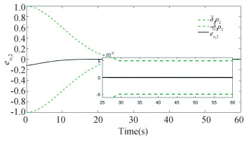
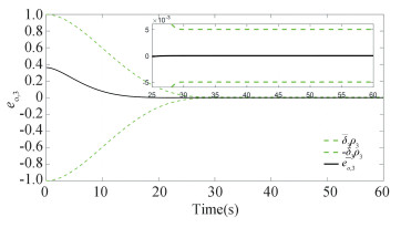
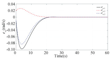
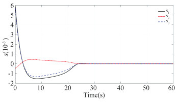
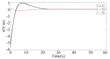
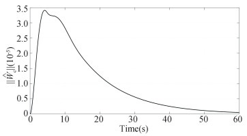
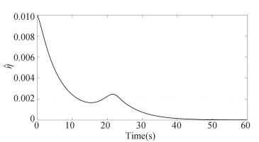
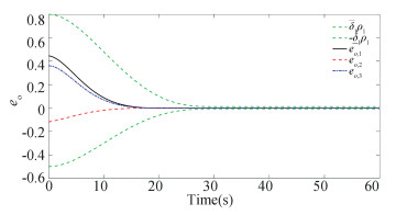
For the initial condition R(0)=exp(πe3/2)exp(-πe2/3)exp(πe1/6) and ω(0)=[-0.01, 0.02, -0.01]T, the constructed scheme is applied to the spacecraft attitude system for 60 s. The simulation results are presented in Figs. 2-7. The constraint boundary referred in Eq.(7) is denoted by the green dotted line in Figs. 2-4. From these figures, it follows that all these components can enter into the predefined error tolerant boundary within the appointed time, i.e., |eo, i| < ρ∞, i, ∀t≥tf=30s, and converge into the small set |eo, i|≤1×10⁻⁵ ultimately. Fig. 5 displays the time response curve for the angular velocity tracking error, from which it can be observed that it will converge into the small set ||eω||≤2×10⁻⁶ ultimately. The convergence curve of the transformed tracking error ||s||≤5×10⁻⁶, as shown in Fig. 6. Fig. 7 displays the requisite control torque. The time response curve of the F-norm of the weight matrix of the actor and critic networks are shown in Figs. 8-9, respectively, and the convergence curve of

|
Fig.2 Time response of eo, 1 |
|
Fig.3 Time response of eo, 2 |
|
Fig.4 Time response of eo, 3 |
|
Fig.5 Time response of eω |
|
Fig.6 Time response of s |
|
Fig.7 Time response of τ |
|
Fig.8
Time response of |

|
Fig.9
Time response of |
|
Fig.10
Time response of |
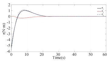
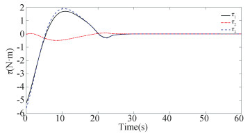
From the proposed control torque given in Eq.(11), it follows that the constructed controller depends on the inertia matrix J. But in practical application, it is almost impossible to obtain the exact value of the moment of inertia. Thus, only the nominal parameter can be utilized in the controller implement. To verify the robustness of the constructed strategy with respect to the model uncertainties, it is further considered that the parameter uncertainties δJ be changed to δJ=20%J, 50%J, 100%J. The simulation results are given in Figs. 11-16. It can be easily observed from these results that the attitude tracking error under the proposed control scheme is still within the predefined constraints in the face of the strong parameter uncertainties. The error will enter into the area |eo, t|≤5×10⁻⁶, |eo, t|≤2×10⁻⁵, |eo, t|≤4×10⁻⁵ under the uncertainties δJ=20%J, 50%J, 100%J, respectively, all of which meet the assigned steady-state constraint. It is verified by the simulation example that the performance boundary defined by the appointed-time performance function is always satisfied and the control system performs well even in the challenging situations. In conclusion, although the proposed controller is based on the system parameter, it has strong robustness against the parameter uncertainties.
|
Fig.11 The attitude error under δJ=20%J |
|
Fig.12 The control input under δJ=20%J |

|
Fig.13 The attitude error under δJ=50%J |

|
Fig.14 The control input under δJ=50%J |

|
Fig.15 The attitude error under δJ=100%J |
|
Fig.16 The control input under δJ=100%J |
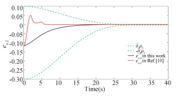
In addition, to further show the merit of the constructed control scheme, a comparison is conducted with the existing fixed-time result[10]. The parameters of the prescribed performance boundary are set as δ=[0.5, 0.1, 0.4]T, δ=[0.1, 0.3, 0.1]T. The controller parameters for the proposed scheme are the same as above, and the parameters for the controller[10] are the same with those in their original work. The ith component for the attitude tracking error eo of the controller (11) herein and the controller (22) in Ref. [10] are put together, as shown in Figs. 17-19. From the comparison results, it can be concluded that the prescribed transient performance can always be achieved under the constructed controller, while the error trajectory of Ref. [10] traverses the predefined boundary, i.e., the transient performance cannot be predesigned.

|
Fig.17 The comparison curve of eo, 1 |
|
Fig.18 The comparison curve of eo, 2 |

|
Fig.19 The comparison curve of eo, 3 |
4 Conclusions
In this paper, a novel adaptive geometric controller is presented based on AC-NNs scheme for the spacecraft attitude tracking subjected to the external disturbance and prescribed performance constraints. By virtue of the error transformation approach and the appointed-time prescribed performance function, the attitude tracking error can be enforced into the predefined tolerant boundary before the specified settling time. Unlike the current NN-based attitude control schemes, a novel critic NN is introduced to evaluate the present tracking performance and correct the control actor for the performance improvement. Although the proposed control strategy involves the model parameter, it is verified in the simulation that the control system has strong robustness to the parameter uncertainties. In the future research, we will focus on saving communication and computation resource by applying the event-triggered mechanism.
| [1] |
Xie R, Song T, Shi P, et al. Model-free adaptive control for spacecraft attitude. Journal of Harbin Institute of Technology (New Series), 2016, 23(6): 61-66. DOI:10.11916/j.issn.1005-9113.2016.06.009 (  0) 0) |
| [2] |
Xia X W, Jing W X, Gao C S, et al. Attitude control of spacecraft during propulsion of swing thruster. Journal of Harbin Institute of Technology (New Series), 2012, 19(1): 94-100. DOI:10.11916/j.issn.1005-9113.2012.01.019 (  0) 0) |
| [3] |
Chaturvedi N A, Sanyal A K, McClamroch N H. Rigid-body attitude control using rotation matrices for continuous, singularity-free control laws. IEEE Control System Magazine, 2011, 31(3): 30-51. DOI:10.1109/MCS.2011.940459 (  0) 0) |
| [4] |
Lee T. Exponential stability of an attitude tracking control system on SO(3) for large-angle rotational maneuvers. System and Control Letter, 2012, 61(1): 231-237. DOI:10.1016/j.sysconle.2011.10.017 (  0) 0) |
| [5] |
Berkane S, Tayebi A. Construction of synergistic potential functions on SO(3) with application to velocity-free hybrid attitude stabilization. IEEE Transactions on Automatic Control, 2017, 62(1): 495-501. DOI:10.1109/TAC.2016.2560537 (  0) 0) |
| [6] |
Gui H, Vukovich G. Robust switching of modified Rodrigues parameter sets for saturation global attitude control. Journal of Guidance Control Dynamic, 2017, 40(6): 1529-1536. DOI:10.2514/1.G002339 (  0) 0) |
| [7] |
Shi X N, Zhou Z G, Zhou D. Finite-time attitude trajectory tracking control of rigid spacecraft. IEEE Transactions on Aerospace Electronic Systems, 2017, 53(6): 2913-2923. DOI:10.1109/TAES.2017.2720298 (  0) 0) |
| [8] |
Gao S H, Jing Y W, Liu X P, et al. Finite-time adaptive fault-tolerant control for rigid spacecraft attitude tracking. Asian Journal of Control, 2021, 23(2): 1003-1024. DOI:10.1002/asjc.2277 (  0) 0) |
| [9] |
Sun H B, Hou L L, Zong G D, et al. Fixed-time attitude tracking control for spacecraft with input quantization. IEEE Transactions on Aerospace and Electronic Systems, 2019, 55(1): 124-134. DOI:10.1109/TAES.2018.2849158 (  0) 0) |
| [10] |
Shi X N, Zhou Z G, Zhou D. Adaptive fault-tolerant attitude tracking control of rigid spacecraft on Lie group with fixed-time convergence. Asian Journal of Control, 2020, 22(1): 423-435. DOI:10.1002/asjc.1888 (  0) 0) |
| [11] |
Wang Y L, Tang S J, Guo J, et al. Fuzzy-logic-based fixed-time geometric backstepping control on SO(3) for spacecraft attitude tracking. IEEE Transactions on Aerospace and Electronic Systems, 2019, 55(6): 2938-2950. DOI:10.1109/TAES.2019.2896873 (  0) 0) |
| [12] |
Shi X N, Zhou Z G, Zhou D, et al. Event-triggered fixed-time adaptive trajectory tracking for a class of uncertain nonlinear systems with input saturation. IEEE Transactions on Circuits and Systems-Ⅱ: Express Briefs, 2021, 68(3): 983-987. DOI:10.1109/TCSII.2020.3018194- (  0) 0) |
| [13] |
Chen F, Dimarogonas D V. Leader-follower formation control with prescribed performance guarantees. IEEE Transactions on Control of Network Systems, 2021, 8(1): 450-461. DOI:10.1109/TCNS.2020.3029155 (  0) 0) |
| [14] |
Shojaei K, Chatraei A. Robust platoon control of underactuated autonomous underwater vehicles subjected to nonlinearities, uncertainties and range and angle constraints. Applied Ocean Research, 2021, 110: 102594. DOI:10.1016/j.apor.2021.102594 (  0) 0) |
| [15] |
Zhou Z G, Zhang Y A, Shi X N, et al. Robust attitude tracking for rigid spacecraft with prescribed transient performance. International Journal of Control, 2017, 90(11): 2471-2479. DOI:10.1080/00207179.2016.1250955 (  0) 0) |
| [16] |
Shao X D, Hu Q L, Shi Y, et al. Fault-tolerant prescribed performance attitude tracking control for spacecraft under input saturation. IEEE Transactions on Control Systems Technology, 2020, 28(2): 574-582. DOI:10.1109/TCST.2018.2875426 (  0) 0) |
| [17] |
Han S. Prescribed consensus and formation error constrained finite-time sliding mode control for multi-agent mobile robot systems. IET Control Theory Applications, 2018, 12(2): 282-290. DOI:10.1049/iet-cta.2017.0351 (  0) 0) |
| [18] |
Li X L, Luo X Y, Wang J G, et al. Finite-time consensus of nonlinear multi-agent system with prescribed performance. Nonlinear Dynamics, 2018, 91(4): 2397-2409. DOI:10.1007/s11071-017-4020-1 (  0) 0) |
| [19] |
Wei C S, Luo J J, Yin Z Y, et al. Leader-following consensus of second-order multi-agent systems with arbitrarily appointed-time prescribed performance. IET Control Theory Applications, 2018, 12(16): 2276-2286. DOI:10.1049/iet-cta.2018.5158 (  0) 0) |
| [20] |
Guo S H, Liu X P, Jing Y W, et al. A novel finite-time prescribed performance control scheme for spacecraft attitude tracking. Aerospace Science and Technology, 2021, 118: 107044. DOI:10.1016/j.ast.2021.107044 (  0) 0) |
| [21] |
Song Z K, Sun K B. Prescribed performance adaptive control for an uncertain robotic manipulator with input compensation updating law. Journal of the Franklin Institute, 2021, 358(16): 8396-8418. DOI:10.1016/j.jfranklin.2021.08.036 (  0) 0) |
| [22] |
Wang H Q, Bai W, Zhao X D, et al. Finite-Time Prescribed Performance-Based Adaptive Fuzzy Control for Strict-Feedback Nonlinear Systems with Dynamic Uncertainty and Actuator Faults. https://ieeexplore.ieee.org/stamp/stamp.jsp?tp=&arnumber=9325881, 2022-03-04.
(  0) 0) |
| [23] |
Luo Y H, Sun Q Y, Zhang H G, et al. Adaptive critic design-based robust neural network control for nonlinear distributed parameter systems with unknown dynamics. Neurocomputing, 2015, 148: 200-208. DOI:10.1016/j.neucom.2013.08.049 (  0) 0) |
| [24] |
Lewis F L, Liu D R. Reinforcement Learning and Approximate Dynamic Programming for Feedback Control. Hoboken, NJ: John Wiley & Sons Inc., 2012.258-278.
(  0) 0) |
| [25] |
Zhao J, Na J, Gao G B. Adaptive dynamic programming based robust control of nonlinear systems with unmatched uncertainties. Neurocomputing, 2020, 395: 56-65. DOI:10.1016/j.neucom.2020.02.025 (  0) 0) |
| [26] |
Song R Z, Lewis, F L. Robust optimal control for a class of nonlinear systems with unknown disturbances based on disturbance observer and policy iteration. Neurocomputing, 2020, 390: 185-195. DOI:10.1016/j.neucom.2020.01.082 (  0) 0) |
| [27] |
Ouyang Y C, Dong Y L, Wei Y L, et al. Neural network based tracking control for an elastic joint robot with input constraint via actor-critic design. Neurocomputing, 2020, 409: 286-295. DOI:10.1016/j.neucom.2020.05.067 (  0) 0) |
| [28] |
Zheng Z W, Ruan L P, Zhu M, et al. Reinforcement learning control for underactuated surface vessel with output error constraints and uncertainties. Neurocomputing, 2020, 399: 479-490. DOI:10.1016/j.neucom.2020.03.021 (  0) 0) |
| [29] |
Wang H Q, Kang S J, Zhao X D, et al. Command Filter-Based Adaptive Neural Control Design for Nonstrict-Feedback Nonlinear Systems with Multiple Actuator Constraints. https://ieeexplore.ieee.org/document/9445739, 2022-03-04.
(  0) 0) |
| [30] |
Wang H Q, Xu K, Liu P X, et al. Adaptive fuzzy fast finite-time dynamic surface tracking control for nonlinear systems. IEEE Transactions on Circuits and Systems-Ⅰ: Regular Papers, 2021, 68(10): 4337-4348. DOI:10.1109/TCSI.2021.3098830 (  0) 0) |
 2023, Vol. 30


