With the "Zhurong" Mars rover landing on Mars and starting cruise exploration, China's deep space exploration has opened a new chapter. The mobile performance of the planetary rover is the key factor to ensure the realization of its cruising mission, and the ground microgravity compensation environment is an important link to study the mobile performance of the planetary rover[1]. Various deep space exploration missions put forward higher requirements for microgravity simulation research.
At present, the research results of practical microgravity compensation are rich and there are many methods, including the drop tower[2], the neutral buoyancy system[3], the air floatation system[4], the magnetic levitation system[5], the sling suspension system[6], etc. The sling suspension system is most suitable for microgravity environment simulation of planetary rover walking, and it has also been widely used in many fields. NASA[7] developed a variety of active and passive suspended microgravity simulation systems for LSSM manned vehicles and other purposes. Carnegie Mellon University[8] proposed a microgravity simulation system of manipulator named CGI and CGII, which uses two-dimensional servo system combined with counterweight compensation. Harvard University[9] and the University of California[10] designed a microgravity simulation device of astronauts' walking and running, which uses pulley-sling system to realize tracking and spring device to buffer disturbance. The Mars rover microgravity simulation system of the Russian Institute of Mobile Vehicle Engineering[11] adopted single-cable suspension and realized force distribution with the help of multipoint distribution mechanism. Fujitsu corporation of Japan and Tokyo Metropolitan University of Science and Technology[12] presented a microgravity simulation system for dual arm space robot. There are also many examples of microgravity simulation with the help of the sling suspension system in China. Liu[13]designed a passive gravity compensation method for lunar rover based on the principle of static balance. Shenyang Institute of Automation[14-16] designed a gravity compensation system for the lunar rover with multipoint suspension, the microgravity simulation system of panoramic camera turntable with counterweight and azimuth manipulator, and the gravity compensation system of spacecraft docking using spring balancer, single-cable suspension and two-dimensional horizontal servo. Liu et al.[17-18] suspended a space telescopic boom with multi-cable and passive pulley, and the microgravity simulation experiment in the inner field/clean room of the Jade Rabbit lunar rover was successfully carried out by using the active suspension method. Peng and He[19] suspended a spaceborne ring antenna with multi-cable from an electromechanical device that actively generates counterbalance force. Zhu et al.[20] developed a gravity simulation system of separation mechanism suspended by counterweight and single cable. Wu et al.[21] combined the suspension method with two-dimensional air-floating slide rail for a microgravity simulation system of solar array. Zhang et al.[22] developed a microgravity simulation system of solar array, which uses vacuum adsorption horizontal roof to realize two-dimensional tracking and constant force spring to realize multi-cable suspension.
The common feature of the above gravity compensation system is that the support truss structure is complex, and the system error caused by the physical characteristics such as mechanical structure accuracy and pulley friction is the key factor affecting the simulation accuracy.
In view of this, this paper proposes:
1) Position tracking and gravity compensation method based on magnetic levitation macro following with frictionless and suspended micro-motion fine tuning.
2) Multi module fusion design of gravity compensation system based on function division, and the feasibility is verified by simulation experiments.
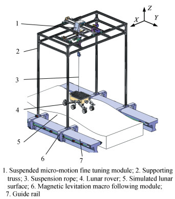
1 Design of Suspended Gravity Compensation System with Magnetic Levitation Servo 1.1 Overall DesignThis system is composed of magnetic levitation macro following module and suspended micro-motion fine tuning module. The suspension module is installed on the support truss of the maglev module. The suspension rope is connected with the mass center of the lunar rover. With the help of the multi-dimensional arrangement of various sensors, the two modules obtain the force and position information of the suspension point relative to the lunar rover in real time, and the fusion processing based on feedback information cooperatively drives the microgravity compensation system to realize the microgravity simulation experiment of the walking process of the six degree of freedom lunar rover. The overall composition of the system is shown in Fig. 1.
|
Fig.1 Microgravity compensation system of lunar rover |
The suspension module comprises a position servo component and a constant force component. The position servo component has two degrees of freedom (X and Y). The fine tuning of the suspension point position is completed with the help of the orthogonal lead screw drive; the constant force component has a degree of freedom in the Z direction, and the constant force output of the suspension rope is maintained with the help of the constant torque servo motor and the winch, as shown in Fig. 2.

|
Fig.2 Suspended micro-motion fine tuning module |
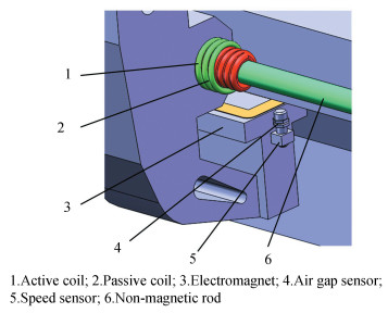
The magnetic levitation system consists of two functional units: levitation and propulsion, as shown in Fig. 3. The levitation unit is realized by the magnetic attraction between the electromagnet and the guide rail. The active coil of the propulsion unit is connected with AC (alternating current) to generate air gap magnetic field, and the passive coil generates induced magnetic field, which is fixed on the non-magnetic rod of the guide rail. The interaction of the two magnetic fields pushes the system forward.
|
Fig.3 Magnetic levitation macro following module |
1.2 Working Principle
In the initial state, the levitation unit generates magnetic attraction, maintains stable levitation with the help of air gap sensor, and realizes gravity compensation for the whole system. Using the interaction between active coil and passive coil, the speed sensor feedback controls the propulsion unit to realize the macro tracking of lunar rover. When the suspension rope deviates from the vertical direction, the real-time feedback of the angle sensor is used to control the movement of the position servo component to achieve accurate following in a small range. With the change of lunar surface morphology, the vertical displacement of the suspension point is caused and the compensation force changes. The constant tension control is realized by controlling the constant force component to retract and release the suspension rope with the feedback of tension sensor. Finally, the high-precision microgravity compensation suitable for the lunar surface morphology walking experiment is achieved.
In order to ensure the normal operation of gravity compensation system, suspended micro-motion fine tuning module and magnetic levitation macro following module are studied respectively to realize high-precision constant tension control, fast position tracking control and stable suspension control.
2 Control Principle and Simulation Analysis of Suspended Micro-motion Fine Tuning Module 2.1 Dynamic ModelAccording to the motion characteristics of each component of the suspension module, the coordinate system[23] is established, as shown in Fig. 4.

|
Fig.4 Coordinate system of microgravity compensation system |
In Fig. 4, O-UVW is a fixed coordinate system, the origin O is the initial position, U and V correspond to two degrees of freedom of the position servo components respectively. P-XYZ is the coordinate system of position servo component, and the origin P is the suspension point. P-xyz is the coordinate system of the constant suspension force component, and z axis is always along the direction of the suspension rope. Pj-XjYjZj is the hanger coordinate system, and the hanger connects the magnetic levitation module and the suspension module.
Through the establishment and analysis of the coordinate system, it can be found that the suspension module consists of 7 generalized coordinates called x, y, θx, θy, l, xj and yj. According to Lagrange dynamics equation, the dynamic equation of the compensation system is established:
| $ \begin{gathered} \boldsymbol{A}\left[\begin{array}{l} \ddot{x} \\ \ddot{y} \end{array}\right]+\boldsymbol{B}\left[\begin{array}{l} \ddot{x}_j \\ \ddot{y}_j \end{array}\right]+\boldsymbol{C}\left[\begin{array}{l} \dot{\theta}_x \\ \dot{\theta}_y \end{array}\right]+\boldsymbol{D}\left[\begin{array}{l} \ddot{\theta}_x \\ \ddot{\theta}_y \end{array}\right]+ \\ \boldsymbol{E}\left[\begin{array}{l} \dot{l} \\ \ddot{l} \end{array}\right]+\boldsymbol{F}\left[\begin{array}{l} \dot{\theta}_x^2 \\ \dot{\theta}_y^2 \end{array}\right]+\boldsymbol{G}=\boldsymbol{H} \end{gathered} $ | (1) |
The coefficients of matrixes are expressed as follows:
| $ \boldsymbol{A}=\left[\begin{array}{cc} M_x+m & 0 \\ 0 & M_y+m \\ m l\cos \theta_x\cos \theta_y & 0 \\ -m l\sin \theta_x\sin \theta_y & m l\cos \theta_y \\ M_x+m & 0 \\ 0 & M_y+m \\ m l\cos \theta_y\sin \theta_x & m\sin \theta_y \end{array}\right] $ |
| $ \boldsymbol{B}=\left[\begin{array}{cc} M_x+m & 0 \\ 0 & M_y+m \\ m l\cos \theta_x\cos \theta_y & 0 \\ -m l\sin \theta_x\sin \theta_y & 0 \\ M_{j x}+M_x+m & 0 \\ 0 & M_{j y}+M_y+m \\ m l\cos \theta_y\sin \theta_x & 0 \end{array}\right] $ |
| $ \boldsymbol{C}=\left[\begin{array}{cc} 2 m \dot{l}\cos \theta_x\cos \theta_y-2 m l \dot{\theta}_y\cos \theta_x\cos \theta_y & 2 m \dot{l}\sin \theta_x\sin \theta_y \\ 0 & 2 m \dot{l}{\cos \theta_y} \\ 2 m \dot{l} {\cos}^2 \theta_y-2 m l^2 \dot{\theta}_y\cos \theta_y\sin \theta_y & 0 \\ 0 & 2 m l \dot{l} \\ 2 m \dot{l}\cos \theta_x\cos \theta_y-2 m l \dot{\theta}_y\cos \theta_x\cos \theta_y & 2 m \dot{l}\sin \theta_x\sin \theta_y \\ 0 & 2 m \dot{l}\cos \theta_y \\ 0 & 0 \end{array}\right] $ |
| $ \boldsymbol{D}=\left[\begin{array}{cc} ml\cos \theta_x\cos \theta_y & -m l\sin \theta_x\sin \theta_y \\ 0 & m l\cos \theta_y \\ ml^2\cos ^2 \theta_y & 0 \\ 0 & m l^2 \\ ml\cos \theta_x\cos \theta_y & -m l\sin \theta_x\sin \theta_y \\ 0 & m l\cos \theta_y \\ 0 & 0 \end{array}\right] $ |
| $ \boldsymbol{E}=\left[\begin{array}{cc} & m\sin \theta_x\cos \theta_y \\ 0 & m\sin \theta_y \\ 0 & 0 \\ 0 & 0 \\ 0 & m\sin \theta_x\cos \theta_y \\ 0 & m\sin \theta_y \\ 0 & \frac{I}{R}+m \\ 0 & \end{array}\right] $ |
| $ \boldsymbol{F}=\left[\begin{array}{cc} -m l\sin \theta_x\cos \theta_y & -m l\sin \theta_x\cos \theta_y \\ 0 & -m l\sin \theta_y \\ 0 & 0 \\ m l^2\cos \theta_y\sin \theta_y & 0 \\ -m l\sin \theta_x\cos \theta_y & -m l\sin \theta_x\cos \theta_y \\ 0 & -m l\sin \theta_y \\ -m l\cos ^2 \theta_y & -m l \end{array}\right] $ |
| $ \boldsymbol{G}=\left[\begin{array}{c} 0 \\ 0 \\ m g l\sin\theta_x\cos\theta_y \\ m g l\sin\theta_y\cos\theta_x \\ 0 \\ 0 \\ -m g\cos\theta_x\cos\theta_y \end{array}\right] $ |
| $ \boldsymbol{H}=\left[\begin{array}{c} F_x-C_x \dot{x} \\ F_y-C_y \dot{y} \\ J_x l\cos \theta_x-C_s \dot{\theta}_x \\ J_y l\cos \theta_y-C_s \dot{\theta}_y \\ F_{j x}-C_j \dot{x}_j \\ F_{j y}-C_j \dot{y}_j \\ F_l-C_l \dot{l} \end{array}\right] $ |
In Eq. (1), θx and θy are the deflection angle of the suspension rope, m is the mass of the lunar rover, Mx and My are the mass of the position servo components, Cx and Cy are the sliding damping coefficients of the position servo component, Jx and Jy are the generalized forces corresponding to the θx and θy directions of the lunar rover, respectively. Cs is the swing damping coefficient of suspension rope. Cl is the damping coefficient of the suspension rope and Fl is the generalized force on the suspension rope. x and y are the displacement of the suspension point in U- and V-directions, xj and yj are the displacement of the hanger in U- and V-directions, l is the length of the suspension rope, I is the moment of inertia of the drum, R represents the radius of the drum, Cj is the damping coefficient of the hanger, Fx and Fy are the generalized forces corresponding to the coordinates x and y, Fjx and Fjy are the generalized forces corresponding to the coordinates xj and yj.
2.2 Decoupling AnalysisIn order to facilitate the control, the dynamic Eq. (1) is linearly decoupled. By observing Eq. (1), it can be seen that there is symmetry between the two position servo components. In addition, since the deflection angle of the suspension rope is very small, sinθx≈θx, sinθy≈θy, cosθx≈1, cosθy≈1. Finally, the equation can be further simplified to Eqs. (2)-(5):
| $ (M+m) \times\left(\ddot{x}+\ddot{x}_j\right)+m l \ddot{\theta}+C \dot{x}=F $ | (2) |
| $ m l \ddot{\theta}+m \ddot{x}_j+m \ddot{x}+m g \theta+\frac{C_s \dot{\theta}}{l}=J $ | (3) |
| $ \left(\frac{I}{R^2}+m\right) l-m g+C_l \dot{l}=F_l $ | (4) |
| $ M_j \ddot{x}_j+(M+m) \times\left(\ddot{x}+\ddot{x}_j\right)+m l \ddot{\theta}+C_j \dot{x}_j=F_j $ | (5) |
The meanings of parameters in Eqs. (2)-(5) is the same as that in Eq. (1).θ is the deflection angel of the suspension rope, F represents the generalized force of the position servo component, Fj is the generalized force of the hanger.
2.3 Control System Design and Simulation Analysis 2.3.1 Control Strategy and Controller DesignDue to the external interference force, the tension accuracy of the constant force component only using position control is not high. Therefore, the force/position hybrid control is introduced, that is, the force feedback control is realized by comparing the actual tension of the suspension rope with the target force collected by the mechanical sensor, and then it is combined with the position control to realize the high-precision adjustment of the tension of the suspension rope. The position controller adopts PD (proportional-differential) control, and the constant force controller adopts PI (proportional-integral) controller.
Since the servo components in U- and V-directions are independent and symmetrical, the design of control system in one direction can be enough. Taking the V-direction servo component as an example. According to the geometric relationship, the interference force can be expressed as Eq. (6):
| $ F_d=F_l\sin\theta $ | (6) |
In order to eliminate the influence of interference force, the constraint conditions are established as shown in Eq. (7)[24]:
| $ \left\{\begin{array}{l} \int_{t_0}^{t_j} \theta \mathrm{d} t \rightarrow 0 \\ \theta\left(t_j\right) \rightarrow 0 \\ \dot{\theta}\left(t_j\right) \rightarrow 0 \end{array}\right. $ | (7) |
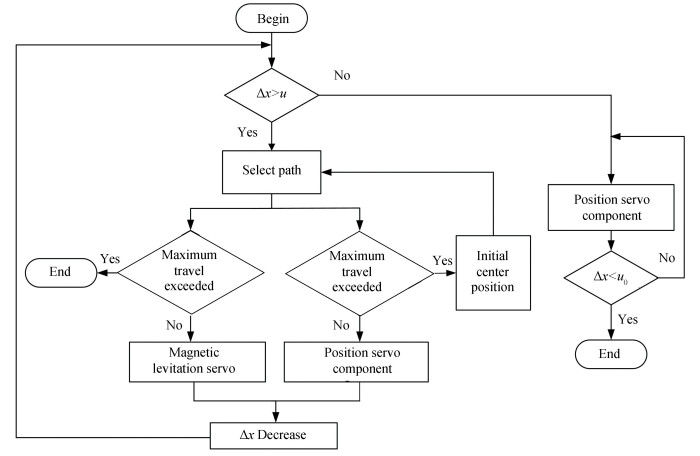
Due to the coupling relationship between maglev macro module and suspended micro-motion module, in order to avoid the instability caused by simultaneous motion, the method of limiting amplitude is adopted to establish the overall control of the follow-up part of the lunar rover gravity compensation system, as shown in Fig. 5.
|
Fig.5 Control scheme of position servo of microgravity compensation system |
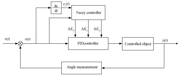
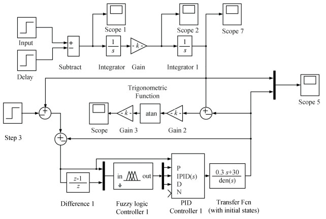
When the position deviation (Δx) is greater than u(u is a certain value), it is necessary to comprehensively consider the position servo component and magnetic levitation system. In order to meet the requirements of experiment, the fuzzy PID control is introduced. The common two-dimensional controller structure of fuzzy adaptive PID controller is shown in Fig. 6.
|
Fig.6 Structure of fuzzy adaptive PID controller |
The fuzzy controller takes angle error (e(t)) and differential value of angular error (ec(t)) as input and outputs the adjustment values of proportion, integral and differential coefficients (i.e., ΔKp, ΔKI and ΔKD). After the steps of fuzzification, fuzzy reasoning and anti-fuzzification, it combines the adjustment value with the initial design value of PID controller to form a new position controller[25], as shown in Eq. (8):
| $ \left\{\begin{array}{l} K_p=K_{p 0}+\Delta K_p \\ K_I=K_{l 0}+\Delta K_I \\ K_D=K_{D 0}+\Delta K_D \end{array}\right. $ | (8) |
The fuzzy set is expressed as seven states: negative large (NL), negative middle (NM), negative small (NS), zero (ZE), positive small (PS), positive middle (PM), and positive large (PL), and then the domain range of e and ec is [-6, 6], ΔKp is [8, 12], ΔKI is [45, 55], ΔKD is [3, 7], and trigonometric function is selected as membership function.
The control rules are shown in Table 1.
| Table 1 Fuzzy rule |
2.3.2 Simulation Experiment
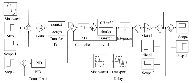
The hybrid force/position control simulation model of the constant force component was built in MATLAB SIMULINK, as shown in Fig. 7.
|
Fig.7 Simulation model block diagram of hybrid force/position control |
The reference mass of Yutu lunar rover was 140 kg, and the target force was 1144 N. At the initial state, the pre-tightening force should meet the requirements of gravity compensation experiment to make the whole system in static equilibrium. As the mass of rope and damping coefficient had little impact on the system performance, they could be ignored. The simulation process was divided into the following two stages:
1) Stationary stage: the lunar rover was stationary; the DC motor outputs constant torque and the suspension rope remained tensioned.
2) Movement stage and disturbance stage: At the 3rd second, the lunar rover began to move, and a disturbance force of 200 N was applied to the suspension rope. The simulation results are shown in Fig. 8.

|
Fig.8 Deviation diagram of suspension rope tension and target force |
It can be seen from Fig. 8 that when the system was subjected to external interference, the tensile force of rope changed, then the hybrid force/position controller could respond quickly. Within 0.2 s, the tensile force returned to the effective range of the target force again, and the error range was maintained within ±1 N. The compensation accuracy reached more than 95%, which meets the design index.
The simulation model of fuzzy adaptive PID controller was established in SIMULINK, as shown in Fig. 9.
|
Fig.9 Simulation model block diagram of fuzzy adaptive PID control |
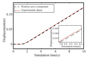
A driving force of 20 N was applied to the mass center of the lunar rover to simulate the horizontal motion of the lunar rover. The experimental results are shown in Figs. 10-12.

|
Fig.10 Speed comparison diagram of position servo component and experimental object |
|
Fig.11 Displacement comparison diagram of position servo component and experimental object |

|
Fig.12 Angle deviation diagram of suspension rope |
Within 1-3 s, the position servo component accelerated continuously. After exceeding the experimental object, it decelerated briefly. Finally, the speed of the position servo component was consistent with that of the experimental object. The position tracking was realized after the 3rd second. The position deviation was less than 5 mm and the angle deviation was less than 0.025°. The simulation results show that the fuzzy adaptive PID control can meet the functional requirements of the system.
3 Control Principle and Simulation Analysis of Macro Following Module 3.1 Control Design of Macro Following ModuleFirstly, the static analysis of the macro following module was carried out, as shown in Fig. 13. The propulsion unit is located on both sides of the suspension hanger, and the levitation unit is distributed around the module[26].

|
Fig.13 Static analysis diagram of macro following module |
In this figure, Fi, (i=1, 2, 3, 4) is the electromagnet suspension force, Ff is the interference force, G is the gravity of the suspension hanger, Fd1 and Fd2 are the propulsion force, A, B, C and D represent four levitation units.
According to the force balance and Kirchhoff voltage law, the dynamic equations of the single levitation unit electromagnet are as follows:
| $ \left\{\begin{array}{l} F(i, x)=\frac{\mu_0 N^2 S i^2(t)}{4 x^2(t)} \\ u=\frac{2 x(t) u(t)}{\mu_0 N^2 S}-\frac{2 x(t) i(t) R}{\mu_0 N^2 S}+\frac{i(t) \dot{x}(t)}{x(t)} \\ \ddot{x}(t)=\frac{f(t)}{m}+g-\frac{F}{m} \end{array}\right. $ | (9) |
where μ0 is the air permeability, N is the coil turn, S is the cross-sectional area of the magnetic pole of the electromagnet, R is the coil resistance, x is the air gap, i is the coil current, u is the coil voltage, m is the mass of levitation unit, F is the magnetic attraction, f is the interference force of the levitation unit.
The magnetic attraction is expanded at the equilibrium point and linearized locally. Ignoring the influence of coil inductance, the system state equation is shown in Eq. (10):
| $ \left[\begin{array}{l} \dot{z}_1 \\ \dot{z}_2 \end{array}\right]=\left[\begin{array}{ll} 0 & 1 \\ 0 & 0 \end{array}\right]\left[\begin{array}{l} z_1 \\ z_2 \end{array}\right]+\left[\begin{array}{l} 0 \\ 1 \end{array}\right] w $ | (10) |
where $w=\frac{f(t)}{m}+g-\frac{\mu_0 N^2 S i^2(t)}{4 m x^2(t)}$
| $ z_1=x(t)-x_0, z_2=\dot{x}(t) $ |
The propulsion unit adopts coaxial coil structure, and the propulsion force can be expressed as[27]
| $ F_d=M(c) I_1 I_2 $ | (11) |
where M(c)= 2μ0r1r20$\int_0^{\frac{\pi}{2}} \frac{2 \sin ^2 \theta-1}{\sqrt{c^2+\left(r_1-r_2\right)^2+4 r_1 r_2 \cos ^2 \theta}} \mathrm{d} \theta$ where M is the mutual inductance coefficient of active coil and passive coil, c is the distance between two coils, I1 and I2 are the current of active coil and passive coil respectively, r1 and r2 are the section radius of the coil.
According to the speed deviation between the gravity compensation system and the lunar rover, the propulsion unit can be divided into three states: advanced state, synchronous following and lag state. The velocity measurement device feedback controls the propulsion unit to realize the macro tracking of the lunar rover. The control block diagram is shown in Fig. 14.

|
Fig.14 Control block diagram of propulsion unit |
3.2 Simulation Experiment
The control block diagram of electromagnet simulation model is established, as shown in Fig. 15.

|
Fig.15 The Simulation model block diagram of suspension unit electromagnet |
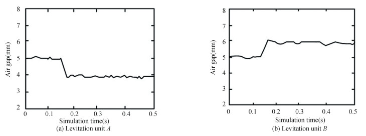
In the synchronous following state, the simulation results of levitation units A and B are shown in Fig. 16.
|
Fig.16 Simulation results of suspension unit electromagnet |
The simulation results show that the external interference makes the air gap mutation at 0.13 s, the levitation unit recovers stability within 0.1 s, maintains balance at the new air gap, and finally realizes stable suspension.
4 Conclusions1) Aiming at the shortcomings of traditional suspension method, a gravity compensation method based on magnetic levitation macro following and suspended micro-motion fine tuning is proposed.
2) The function division and control design of gravity compensation system are carried out. The simulation results show that the system can realize fast position following, constant tension control and stable suspension.
3) The shortcomings of this paper are as follows: the control design is based on the premise of system decoupling, there is a deviation from the actual working condition, and the coupling phenomenon between magnetic levitation macro following module and micro-motion fine tuning module is not analyzed.
| [1] |
Wang Y N. Research on Lunar Rover Synchronous Suspension Gravity Compensation System Based on Magnetic Suspension. Qinhuangdao: Yanshan University, 2020.1-5.
(  0) 0) |
| [2] |
Jiang Y F, Qiao B, Zhao Y. A review of low gravity motion simulation training methods for astronauts. Manned Space Flight, 2018, 24(2): 227-237. DOI:10.16329/j.cnki.zeht.2018.02.014 (  0) 0) |
| [3] |
Zhu Z X, Yuan J P. Construction of Microgravity Environment for Spacecraft Operation. Beijing: China Aerospace Press, 2013: 155-165.
(  0) 0) |
| [4] |
Chen S F, Mei T, Zhang T, et al. Design of the controller for a ground simulation system of spatial microgravity environment. Robot, 2008, 30(3): 201-204. DOI:10.13973/j.cnki.robot.2008.03.003 (  0) 0) |
| [5] |
Scherpen J M A, van der Kerk B, Klaassen J B, et al. Nonlinear control for magnetic bearings in deployment test rigs: simulation and experimental results. Proceedings of the 37th Conference on Decision and Control. Piscataway: IEEE, 1998.2613-2618. DOI: 10.1109/CDC.1998.757846.
(  0) 0) |
| [6] |
Xu Y L, Li X N, Liu Y, et al. Design of the gravity compensation control system in vertical direction on the ground for space manipulator. Robot, 2020, 42(2): 191-198. DOI:10.13973/j.cnki.robot.190042 (  0) 0) |
| [7] |
Wysor R B, Paulnock R S, Farrior S. Third Interim Report Preliminary Design Study of a Lunar Gravity Simulator. https://ntrs.nasa.gov/archive/nasa/casi.ntrs.nasa.gov/19670022528.pdf, 19670022528, 2022-02-28.
(  0) 0) |
| [8] |
Brown H B, Dolan J M. A Novel Gravity Compensation System for Space Robots. https://www.researchgate.net/profile/John-Dolan-6/publication/238034839_A_Novel_Gravity_Compensation_System_for_Space_Robots/links/0046353443965d9cbf000000/A-Novel-Gravity-Compensation-System-for-Space-Robots.pdf, 2022-02-28.
(  0) 0) |
| [9] |
He J P, Kram R, McMahon T A. Mechanics of running under simulated low gravity. Journal of Applied Physiology, 1991, 71(3): 863-870. DOI:10.1152/jappl.1991.71.3.863 (  0) 0) |
| [10] |
Griffin T M, Tolani N A, Kram R. Walking in simulated reduced gravity: mechanical energy fluctuations and exchange. Journal of Applied Physiology, 1999, 86(1): 383-390. DOI:10.1152/jappl.1999.86.1.383 (  0) 0) |
| [11] |
Kemurdjian A, Khakhanov U A. Development of simulation means for a gravity force. Proceedings of the 4th International Conference and Exposition/Demonstration on Robotics for Challenging Situations and Environments. Reston, VA: ASCE, 2000.220-225. DOI: 10.1061/40476(299)28.
(  0) 0) |
| [12] |
Kim M G, Cho S, Tran T Q, et al. Scaled jump in gravity-reduced virtual environments. IEEE Transactions on Visualization and Computer Graphics, 2017, 23(4): 1360-1368. DOI:10.1109/TVCG.2017.2657139 (  0) 0) |
| [13] |
Liu W X. The Passive Lunar Mobile Robot Gravity Compensation Study. Beijing: Beijing University of Posts and Telecommunications, 2015.5-10.
(  0) 0) |
| [14] |
Xu Z G, Wang H, Wang J Y, et al. The research of space robot suspension system gravity compensation. Machinery Design and Manufacture, 2014, 10: 149-152. DOI:10.19356/j.cnki.1001-3997.2014.10.045 (  0) 0) |
| [15] |
Yang Y, Chang Y, Wang H G, et al. A low gravity compensation device of panoramic camera turntable. Machinery Design and Manufacture, 2018, 9: 16-20. DOI:10.19356/j.cnki.1001-3997.2018.09.005 (  0) 0) |
| [16] |
Xu Z G, Xin L M, Zhao M Y. Gravity balance technique of active docking ring for spacecraft docking test table. Chinese Journal of Scientific Instrument, 2009, 30(6): 1140-1144. DOI:10.19650/j.cnki.cjsi.2009.06005 (  0) 0) |
| [17] |
Liu R Q, Guo H W, Deng Z Q. Design and experimental study of space cable strut articulated boom. Journal of Astronautics, 2009, 30(1): 315-320. DOI:10.3873/j.issn.1000-1328.2009.00.057 (  0) 0) |
| [18] |
Liu Z. Sling-cable Gravity Compensation for Planetary Rovers and Experimental Researches. Harbin: Harbin Institute of Technology, 2013.5-10.
(  0) 0) |
| [19] |
Peng H, He B Y. A new gravity compensation method of space-borne perimeter truss deployable reflectors. China Mechanical Engineering, 2019, 30(4): 379-384. DOI:10.3969/j.issn.004-132X.2019.04.001 (  0) 0) |
| [20] |
Zhu C, Guo T, Li X L, et al. Microgravity Test System of Separation Mechanism. China: CN108760267A, 2018-11-06.
(  0) 0) |
| [21] |
Wu Y M, Luo Q, Wang X, et al. Design and verification of Air-floating suspension gravity compensation device for solar wing. Journal of Mechanical Engineering, 2020, 56(13): 149-155. DOI:10.3901/JME.2020.13.149 (  0) 0) |
| [22] |
Zhang J B, Wang H, Li Y, et al. Gravity compensation technology of solar array based on vacuum negative pressure adsorption. Journal of Mechanical Engineering, 2020, 56(5): 202-210. DOI:10.3901/JME.2020.05.202 (  0) 0) |
| [23] |
Zou S Y. Research on Technologies of Horizontal Position Tracking for Suspended Zero-Gravity Simulation System. Harbin: Harbin Institute of Technology, 2014.5-10.
(  0) 0) |
| [24] |
Zou S Y, Liu Z, Gao H B, et al. Tracking control method for suspended floater based on time integral of disturbance force. Robot, 2015, 37(1): 1-8+16. DOI:10.13973/j.cnki.robot.2015.0001 (  0) 0) |
| [25] |
Song Y F, Mei T. Application of fuzzy PID controller in micro-gravity system. Automation and Instrumentation, 2006, 21(2): 37-40. DOI:10.19557/j.cnki.1001-9944.2006.02.012 (  0) 0) |
| [26] |
Liu J. Study on Gravity Compensation Magnetic Suspension Follow-up System of Lunar Rover. Qinhuangdao: Yanshan University, 2020.25-30.
(  0) 0) |
| [27] |
Chen J B, Zhu X. The approximate analytic formula of the mutual inductance between two discretionary coaxial loops. Journal of Logistical Engineering University, 2010, 26(5): 86-91. DOI:10.3969/j.issn.1672-7843.2010.05.17 (  0) 0) |
 2023, Vol. 30


