2. Beijing Aerospace Measurement & Control Technology Co., Ltd., Beijing 100041, China
In recent years, wall climbing robots have been playing an increasingly important role in research and industry field, such as cleaning of high-altitude buildings, rescue mission in dangerous environment, large-scale steel structure building surface inspection and hull surface cleaning. They can also contribute significantly to manual completion of fault diagnosis, fault warning, and state maintenance of major facilities. It is an important tool to replace humans in completing certain tasks in dangerous, complex and confined environments. Certainly, a variety of wall climbing robots have already been designed and manufactured to help liberate human beings from heavy labor. According to the locomotion system, wall climbing robots can be divided into three major types, wheeled robots, legged robots and tracked robots. In order to solve project problems in different working conditions, the adsorption method of wall climbing robots is also various. At present, major adsorption methods contain negative pressure adsorption, magnetic adsorption, electrostatic adsorption and claw gripping adsorption. For the purpose of improving climbing mobility of wall climbing robots, experts and scholars at home and abroad have presented many designs for different working purposes.
Climbing robots using the approach of magnetic adsorption are usually applied to the inspection of above ground steel storage structures, removal of ship rust and some tasks in dangerous environment[1-3]. The magnetic wheel in Ref. [4] consists of four layer-structures allowing the robot to complete forward, backward and steering actions on a vertical ferromagnetic surface. The first part is mild steel (MS) disk1 with hub, the second is magnetic ring, the third is MS disk2 and the forth is rubber grip to protect magnetic ring from the ferrous dust particles. MS disk1 with hub is provided for mounting the rest of three parts as well as to connect a DC motor. However, its load capacity is poor. A wall climbing robot with high capacity was proposed in Ref. [5] and it consists of three magnetic tread-wheel modules connected by links with two compliant joints, making it carry a weight of 10 kg to move on the vertical ferromagnetic surface. Obvious disadvantages of this robot are large body and huge energy demand. Inspired by the wall-climbing behavior of geckos, some small robots were designed to walk on smooth vertical walls by contacting the climbing surface with feet, which were made of adsorbent materials[6]. The adsorption force generated by the contact of the adsorption material is very small, so the robot must be designed to be very light. Also, its gecko-like gait makes the robot's movement speed very low. In Ref. [7], a high-payload robot was designed. The robot has three main modules. Each main module is equipped with a caterpillar-type belt. On the belt, segment magnets are attached for adhesion force (this belt is called magnetic tread). This magnet tread is driven by a speed control motor. The bionic wall climbing robot that uses complex spiny feet to climb the wall was also proposed in Refs. [8-11]. It employs foot stabs to penetrate the climbing surface to generate the climbing force, so the robot cannot climb on hard surfaces, and its movement flexibility is insufficient. Some other wall climbing robots using negative pressure and static electricity to produce adsorption force have also been studied in recent years[12-16].
As a result of the large contacting area of the track and structure surface, tracked robots are able to walk on the rough surface with high stability compared with wheeled robots. Although legged robots can also walk over barriers easily, their motion speed is obviously lower than that of tracked robots. This paper presents the design of a tracked wall climbing robot with two permanent magnetic adsorption tracks. The purpose of this design is to help human beings complete inspection, welding, cleaning and rescue work on steel structure buildings. In the past decades, many tracked wall climbing robots with permanent magnetic adsorption have been designed and manufactured, but these robots majorly climbed on ferromagnetic surface with an inclination angle of less than 180 degrees. For example, a wall climbing robot with permanent magnetic adsorption mechanism for inspecting the oil tanks was put forward in Ref. [17]. However, only the static force analysis of vertical climbing was presented. The state of tracked wall climbing robot climbing on a surface with an inclination angle of 180 degrees was not mentioned. In this paper, the 180-degree climbing experiment of the robot is completed and also an interesting phenomenon was discovered.
The rest of this paper is organized as follows. An overview of the robotic system and detailed description of adsorption tracks and mechanical system are presents in Section 1. In Section 2, the climbing performance analysis including 90 degrees, and 180 degrees is instructed. Experiments and analysis for studying factors affecting the adsorption stability are carried out in Section 3. Section 4 concludes the paper.
1 Design of Tracked Wall Climbing Robot 1.1 System OverviewTracked locomotion mechanism has been widely applied on various wall climbing robots because of its large contacting area with climbing surface, which provides enough space to install a series of adsorption devices, has good motion ability making the robot move at a high speed, zero-turning radius and is easy to change surface structure. Many researchers had studied on characteristics of tracked robots[18-19]. However, many wall climbing robots designed by researchers in the past adopted a driving chain as the track. It is usually made up of steel, which makes weight of the robot heavy. For example, the wall climbing robot in Ref. [20] consisting of a series of permanent magnet feet weighs 30 kg. These feet were mounted on a driving chain. However, the compound track of this paper's robot weighs only 1.4 kg. The track is made up of a canvas belt, two synchronous belts and magnet units arranged in a special way. The robot realizes its forward, backward and steering movements through the meshing of the synchronous pulley and the synchronous belt. The parts on the upper part of the robot are directly or indirectly connected to the keel structures on the left and right sides through four L-shaped brackets. The central electric control box filled with Large-capacity lithium battery, controllers, sensors and other electronic components is fixed on four L-shaped brackets by screws.
The tracked wall climbing robot in this paper has the following advantages:
1) A wireless control system is applied on the tracked wall climbing robot, which allows people to control the robot to complete the work in a remote distance. This contributes a lot to the future research of automatic motion of wall climbing robots.
2) The small size of the climbing robot and the light robot's weight with large adsorption force makes it flexibly operates in the environment without large working space and adsorbed stably on the surface of steel structures.
3) Design of the tensioning mechanism makes installation and removement of the compound tracks more convenient.
4) The zero-turning radius is able to be completed through differential steering. If the driving wheel on the left side rotates clockwise and the driving wheel on the right side rotates counterclockwise at the same time, the robot will turn right without movement.
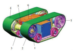
1.2 Mechanical System and Adsorption TracksAs shown in Fig. 1, the tracked wall climbing robot consists of a complete control system fixed on the robot: the permanent magnetic adsorption mechanism, tracked locomotion mechanisms, driving mechanisms, the body frame, and a remote controller. The length, width and height of the robot is 500 mm, 350 mm, and 200 mm respectively and its weight is 12.5 kg including the electric control box weighing 3.3 kg, the mechanical structure weighing 6.2 kg and two adsorption tracks weighing 3 kg. Within a circle with a radius of 10 m, the robot can receive instructions from the remote controller to move and turn. A rechargeable and high-capacity lithium battery is installed in the electric control box, resulting in the robot working continuously for 30 min when the battery is fully charged. When charging the robot, just connect the connector extending from the hole of the electric control box to the power supply through the charger, which is very convenient.
|
1—coupling; 2—driving wheel; 3—motor protective cover; 4—adsorption track; 5—L-shaped bracket; 6—electric control box; 7—passive wheel Ⅰ Fig.1 Three-dimensional structure of tracked wall climbing robot |
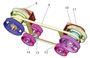
The whole robot has a symmetrical structure whose right part is shown in Fig. 1. Two alternative current (AC) serve motors with the power of 60 W are installed inside the motor protective cover. The left motor and the right motor controlled by microcomputer can deliver the rotating motion through the coupling to the left driving wheel and the right driving wheel respectively. Part 7, Part 11 and Part 12 in Fig. 1 and Fig. 2 are all passive wheels. For the purpose of making the track stay in tensioned state when the robot works, the axel matched with the passive wheel Ⅲ can move arbitrarily in the 200 mm long groove until the track is tensioned. The tension fixture is an auxiliary mechanism to help fix the axe. Two keel structures with strong rigidity are main body frame withstanding the main force and moments of the robot.
|
(8—the motor; 9—keel structure; 10—connection sleeve; 11—the passive wheel Ⅱ; 12—the passive wheel Ⅲ; 13—tension fixture; 14—axel) Fig.2 Right part removed out of the robot |
The three-dimensional structure of the adsorption track is shown in Fig. 3. To guarantee the safety when the robot works on the ferromagnetic surface of high structures, the adsorption track must provide enough adsorption force. Therefore, the adsorption track needs to be wide enough to install enough permanent magnetic units. Two aligned synchronous belts are combined with canvas belts to form a composite track through an industrial bonding approach. The permanent magnetic unit is combined with five small magnets. It can provide a large adsorption force of 40 N. Furthermore, the size of the unit is quite small, which is only 25 mm in length, 13 mm in width and 5 mm in height. The special array mentioned above is called Halbach Array which was first proposed by Halbach in America[21]. The Halbach Array is a creative type of permanent magnet arrangement. It arranges permanent magnets with different magnetization directions in a certain order, so that the magnetic field on one side of the array is significantly enhanced and the other side is significantly weakened, thus effectively increasing the magnetic adsorption force of the whole combination.

|
(15—canvas belt; 16—synchronous belt Ⅰ; 17—permanent magnetic unit; 18—synchronous belt Ⅱ) Fig.3 The adsorption track |
2 Climbing Performance Analysis 2.1 Force Analysis of Vertical Climbing
The state of the tracked wall climbing robot is very typical when it climbs on the vertical wall, because there are three main potential risks. The first risk is that the robot can rotate around the last permanent magnetic adsorption module as a result of the effect of the gravitational moment. Secondly, if the total frictional force between tracks and the ferromagnetic surface is smaller than the gravity of robot and loads, there is no doubt that the robot can slide down. The last risk is that tracks will roll down if the brake torque given by the motors is not large enough. Certainly, many articles have presented the force analysis of vertical climbing. However, one key point mainly causing effect to the first risk of tracked climbing robot was ignored commonly[22]. The tension degree of the track can influence the vertical climbing performance which was studied by few researchers.
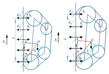
As shown in Fig. 4, a hole with the length of twenty centimeters on the keel structure is designed to tension the track. An axel connected with two small passive wheels is permitted to slide in the long hole for the purpose of seeking for the best tension position. It is obvious that tracks of the climbing robot in Fig. 4 are tensioned so that the straight line connecting the center of the front large wheel and the backward large wheel keeps parallel to the straight line representing the wall. However, compared with the robot in Fig. 4, the rigid frame of the robot in Fig. 5 without tensioned tracks can form an inclining angle with the wall. The blue triangle OAB represents the rigid frame of the tracked wall climbing robot. O is the center of gravity of the robot, B is the point located in the last permanent magnetic module on the track and AB always keeps parallel to the straight line connecting the center of the front large wheel and the backward large wheel. The robot bears forces such as the gravity, adsorption forces produced by many magnets, the supporting force of the wall and the friction force between the tracks and the wall. G is the gravity plus the loading weight of the robot, Fs1 is adsorption force produced by the first magnetic adsorption module, Fsi is the adsorption force produced by the ith magnetic adsorption module. Similarly, N1 and Ni are the first and the ith supporting force of the wall to the magnetic adsorption module, L is the distance of the track adhering to the wall, d is the length of OB, α is the angle between AB and OB and θ is the inclination angle of the robot frame.

|
Fig.4 Static force analysis of the robot with tensioned tracks |
|
Fig.5 Static force analysis of the robot with untensioned tracks |
If the robot rotates around point B, but it still remains the balance status, which is normal to the ferromagnetic surface, N is presented as follows:
| $\sum\limits_{i=1}^n N_i=n \boldsymbol{F}_{s i}$ | (1) |
where n is the number of working permanent magnetic adsorption modules. The adsorption force produced by every magnetic adsorption module is the same, but the supporting force of the wall caused by the torque of gravity is different.
Considering the continuity of adsorption and desorption of permanent magnetic adsorption modules on the track, a part of overlap exists between the previous adsorption module and the next adsorption module. As a result, the stiffness of the track can rise for a little.A stiffness influence coefficient δ is given to represent the effect of this magnet module arrangement on adsorption. If the robot rotates around point B, the first upper magnetic module having a part of overlap with the second upper magnetic module will be lifted. At point B, the torque balance equation is presented as
| $\sum M_B=M_1+M_2=0$ | (2) |
where M1 is torque of the first magnetic module, M2 is torque of gravity. They can be presented respectively as
| $M_1=\left(\boldsymbol{F}_{s 1}-N_1\right) \delta L$ | (3) |
The value of δ varies from 1 to 2.
| $M_2=-\frac{G}{2} d \sin (\theta+\alpha)$ | (4) |
In Fig. 4, the track is tensioned completely, the value of θ is zero. According to Eqs.(2)-(4), the following equation can be obtained:
| $\boldsymbol{F}_{s 1}=\frac{\frac{G}{2} d \sin (\theta+\alpha)}{\delta L}+N_1$ | (5) |
If the first upper magnetic module is absorbed on the wall,
| $N_1 \geqslant 0$ | (6) |
Eq.(5) can be rewritten as
| $\boldsymbol{F}_{s 1} \geqslant \frac{\frac{G}{2} d \sin (\theta+\alpha)}{\delta L}$ | (7) |
When the robot is absorbed on the wall, as shown in Figs. 4 and 5, Ff is the force of friction between the track and the wall. The fore balance equation can be presented as
| $\boldsymbol{F}_f-G=0$ | (8) |
where Ff can be rewritten as
| $\boldsymbol{F}_f=\mu \sum\limits_{i=1}^n N_i$ | (9) |
where μ is the coefficient of friction, according to Eqs. (1), (8) and (9),
| $\mu n \boldsymbol{F}_{s i}-G=0$ | (10) |
If the robot needs to keep absorbing on the wall, the following equation should also be satisfied:
| $\mu n \boldsymbol{F}_{s i}-G \geqslant 0$ | (11) |
Therefore, if the robot needs to keep absorbing on the wall, Eqs. (7) and (11) should be satisfied. The tension degree of the track becomes higher, the value of θ becomes smaller, which contributes a lot to the vertical climbing.
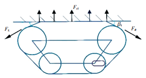
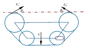
2.2 Force Analysis of 180-Degree Inverted ClimbingWhen a belt with the thickness of one millimeter is set between the permanent magnetic adsorption unit and the ferromagnetic surface, the adsorption force of the unit is 40 N, and the number of magnetic adsorption units absorbing at the same time is more than ten. So, the robot with the weight of 12.5 kg is certainly thought to be able to complete the 180-degree climbing. However, the interesting phenomenon is that the adsorption force between the track and the ferromagnetic surface can increase with the increasing tension degree of the track. In order to illustrate how this phenomenon can appear, static force of the track in the adsorption section is analyzed in Fig. 6. Fsi is the magnetic adsorption force between every magnetic adsorption module and the surface, FL is the fore along the left section of tracks causing the desorption of magnets, FR is the force along the right section of tracks causing the desorption of magnets, β1 is an angle between FL and the surface, β2 is an angle between FR and the surface. Fig. 7 shows the static force analysis of the robot without considering the adsorption section of the track, F′L and F′R are reaction forces of FL and FR, respectively. So, the following equation can be obtained:
| $G-\boldsymbol{F}_{\mathrm{L}}^{\prime} \sin \beta_1-\boldsymbol{F}_{\mathrm{R}}^{\prime} \sin \beta_2=0$ | (12) |
|
Fig.6 Static force analysis of the track in the adsorption section |
|
Fig.7 Static force analysis of the robot without considering the adsorption section of the track |
Only if the center of gravity of the robot locates in the geometric center of the robot can the value of β1 and β2 be equal.
| $\boldsymbol{F}_{\mathrm{L}}^{\prime} \cos \beta_1-\boldsymbol{F}_{\mathrm{R}}^{\prime} \cos \beta_2=0$ | (13) |
| $\boldsymbol{F}_{\mathrm{L}}=\boldsymbol{F}_{\mathrm{L}}^{\prime}$ | (14) |
| $\boldsymbol{F}_{\mathrm{R}}=\boldsymbol{F}_{\mathrm{R}}^{\prime}$ | (15) |
As shown in Fig. 8, the permanent magnetic adsorption units combined by the Halbach method are arranged in a staggered arrangement on the track, end to end. Every magnetic adsorption module consists of three units. When a module at the rear of the robot has not completely detached from the adsorption surface, a module at the front has already begun to adsorb. This arrangement not only conforms to the continuity of the robot's movement, but also increases the rigidity of the track to a certain extent.

|
Fig.8 Arrangement of permanent magnetic adsorption units on the track |
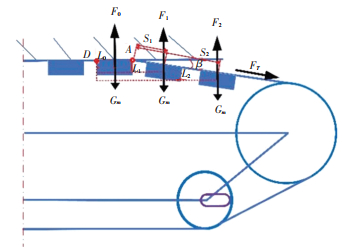
When the climbing robot detaches from the surface, the magnetic adsorption units at two ends detach firstly. As shown in Fig. 9, when the magnetic adsorption unit at point D is rotating around point D but still in the equilibrium, it means the magnetic adsorption unit is going to detach. F0, F1 and F2 are magnetic adsorption forces produced respectively by the first, second and third magnetic adsorption unit. FT is the force along the track which can cause the desorption of the climbing robot, and Gm is the gravity of one magnetic unit. L0, L1 and L2 are distances from F0, F1 and F2 to point D, respectively. S1 is the distance between point A and the first magnetic adsorption unit, S2 is the distance between point A and the second magnetic adsorption unit, and Sn is the distance between point A and the nth magnetic adsorption unit. β is the angle between the section without adsorption and the adsorption surface. If the fixed position of the small wheel moves to the right, the tension degree of the track can be increased, then the angle β will be reduced. So, the change of β reflects the change of tension degree.
|
Fig.9 Static force analysis when the robot is detaching |
It is assumed that the number of magnetic adsorption units on the right of point D is n, the value of force F0 does not vary with β. But the distance from the first nth magnetic adsorption unit to the adsorption surface can increase with the increase of β, and the adsorption force is negatively relative with this distance. So F1 can be defined as a function about β:
| $\boldsymbol{F}_1=f\left(\frac{1}{S_1 \sin \beta}\right)$ | (16) |
Similarly,
| $\begin{array}{c} & {{\boldsymbol{F}}_{2}}=f\left( \frac{1}{{{S}_{2}}\sin \beta } \right) \\ & \cdots \cdots \\ \end{array}$ | (17) |
| $\boldsymbol{F}_n=f\left(\frac{1}{S_n \sin \beta}\right)$ | (18) |
The equation can be obtained by calculating moments about point D, the section of track on the left of point D causes little effect of bending moment to point D, which can be neglected.
| $\begin{aligned} & {\left[\left(\boldsymbol{F}_0-G_m\right) L_0+\left(\boldsymbol{F}_1-G_m\right) L_1+\left(\boldsymbol{F}_2-G_m\right) L_2+\right.} \\ & \left.\quad \cdots\left(\boldsymbol{F}_n-G_m\right) L_n\right]-L_0 \boldsymbol{F}_{\mathrm{T}} \sin \beta=0\end{aligned}$ | (19) |
Adding Eqs. (16), (17), (18) to (19), Eq.(19) can be rewritten as
| $\begin{array}{l} \left(\boldsymbol{F}_0-G_m\right) L_0+\sum\limits_{n=1}^n\left[f\left(\frac{1}{S_n \sin \beta}\right)-G_m\right] L_n- \\ \quad L_0 \boldsymbol{F}_{\mathrm{T}} \sin \beta=0\end{array}$ | (20) |
From Eq. (20), it is known that in order to improve the adsorption performance of climbing robots, the tension degree of tracks can be increased to reduce β.
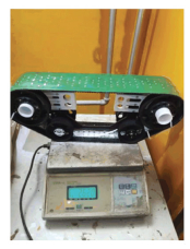
3 ExperimentsIn order to study the relationship between the tension degree of tracks and the adsorption performance of the robot, an adsorption mechanism mainly imitating the half of the robot's mechanism is designed. As shown in Fig. 10, the range of tension degree of the track becomes wider obviously, which makes it easier to observe this interesting phenomenon.
|
Fig.10 The adsorption mechanism |
1) Adsorption on the vertical surface
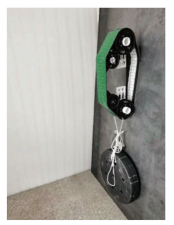
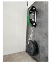
In Fig. 11, the track of adsorption mechanism adsorbed on the vertical surface is not tensioned. When the weight of the load is added continuously, the distance between the upper part of the track and the surface becomes larger. Finally, 15 kg is the maximum weight that the adsorption mechanism can bear. However, the maximum weight the adsorption mechanism can bear increases to 19 kg in Fig. 12. The key for it is the track in Fig. 12 is tensioned enough. As has been discussed above, the force torque caused by the gravity is bigger when the track is not tensioned enough.
|
Fig.11 Adsorption mechanism without tensioned track |
|
Fig.12 Adsorption mechanism with tensioned track |
2) Adsorption on the 180-degree inverted surface
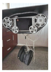
Because the adsorption force of every magnetic unit is 40 N, it is considered that the tracked wall climbing robot could adsorb on the 180-degree inverted surface with the load of more than 40 kg. However, as has been analyzed, the gravity of the load does not act evenly on every magnet. The tension degree of tracks can affect the adsorption performance of the robot obviously. In Fig. 13, 8 kg is set as the extra load of the robot whose weight is 9.5 kg, and it can be seen that the robot is going to desorb the surface. Compared with it, the robot in Fig. 14 is absorbed on the surface stably. The only difference between them is the tension degree of tracks.
|
Fig.13 Robot without tensioned tracks |

|
Fig.14 Robot with tensioned tracks |
Three tension degrees were performed on the adsorption mechanism. A-tension degree is the highest and C-tension degree is the lowest. Maximum loads of the adsorption mechanism with A, B and C tension degree are 13.5 kg, 8 kg and 6 kg, as shown in Fig. 15. Obviously, the higher the tension degree is, the better the adsorption performance is.

|
Fig.15 Adsorption mechanism with different tension degrees |
4 Conclusions
In this paper, the new design of a tracked wall climbing robot is proposed and it has characteristics such as automation with control elements on itself, small size and light weight, zero-turning radius and tension mechanism which contributes a lot to the adsorption performance. The higher the tension degree of robot's tracks is, the better the adsorption performance is. In order to analyze the relationship between the tension degree of tracks and the adsorption performance of the robot, two kinds of static force analysis of the robot absorbed on the vertical surface and 180-degree inverted surface separately are presented. On the vertical surface, the torque caused by gravity can vary with the tension degree of tracks. On the inverted surface, the analysis shows that the angle between the end of the adsorption track and the surface can be affected by the tension degree of tracks, causing the normal force of pulling force along the track to change. Experiments comparing the adsorption performance of the robot with different tension-degree tracks are completed to verify the analysis.
| [1] |
Yi Z Y, Wang X R. Development of a wall climbing robot for ship rust removal. Proceedings of IEEE International Conference on Mechatronics and Automation. Piscataway: IEEE, 2009. 4610-4615. DOI: 10.1109/ICMA.2009.5244801.
(  0) 0) |
| [2] |
Gong Y Z, Wang Z W, Wang X R, et al. Analysis on turning stress states of magnetic sucking mechanism unit of a large load wall climbing robot. Proceedings of International Conference on Measuring Technology and Mechatronics Automation. Piscataway: IEEE, 2010. 570-573. DOI: 10.1109/ICMTMA.2010.642.
(  0) 0) |
| [3] |
Chen X L, Wu Y P, Hao H D, et al. Tracked wall-climbing robot for calibration of large vertical metal tanks. MDPI Applied Sciences, 2019, 9(13): 2671-2687. DOI:10.3390/app9132671 (  0) 0) |
| [4] |
Bisht R S, Pathak P M, Panigrahi S K. Development of magnetic adhesion based wheel-driven climbing machine for ferrous surface application. Proceedings of 2018 Dynamic Systems and Control Conference. New York: ASME, 2018. 1-10. DOI: 10.1115/DSCC2018-9181.
(  0) 0) |
| [5] |
Unver O, Murphy M P, Sitti M. Geckobot and Waalbot: small-scale wall climbing robots. AIAA Infotech@Aerospace, 2005, 6940-6950. DOI:10.2514/6.2005-6940 (  0) 0) |
| [6] |
Kim S, Spenko M, Trujillo S, et al. Smooth vertical surface climbing with directional adhesion. IEEE Transactions on Robotics, 2008, 24(1): 65-74. DOI:10.1109/TRO.2007.909786 (  0) 0) |
| [7] |
Lee G, Wu G, Kim J, et al. High-payload climbing and transitioning by compliant locomotion with magnetic adhesion. Robotics and Autonomous Systems, 2012, 60(10): 1308-1316. DOI:10.1016/j.robot.2012.06.003 (  0) 0) |
| [8] |
Xu F Y, Wang B, Shen J J, et al. Design and realization of the claw gripper system of a climbing robot. Journal of Intelligent & Robotic Systems, 2018, 89: 301-317. DOI:10.1007/s10846-017-0552-3 (  0) 0) |
| [9] |
Liu J F, Xu L S, Xu J J, et al. A bio-inspired wall-climbing robot with claw wheels and adhesive tracks. Proceedings of 2018 IEEE International Conference on Information and Automation (ICIA). Piscataway: IEEE, 2018. 257-262. DOI: 10.1109/ICInfA.2018.8812342.
(  0) 0) |
| [10] |
Wu X, Liu G W, Gao X J, et al. Study of a bioinspired wall-climbing robot: contact mechanism and performance. Proceedings of ASME Conference on Smart Materials, Adaptive Structures and Intelligent Systems. New York: ASME, 2017. 1-10. DOI: 10.1115/SMASIS2017-3729.
(  0) 0) |
| [11] |
Jiang Q S, Xu F Y. Grasping claws of bionic climbing robot for rough wall surface: modeling and analysis. Applied Sciences, 2018, 8(1): 1-15. DOI:10.3390/app8010014 (  0) 0) |
| [12] |
Guan Y S, Zhu H F, Wu W P, et al. A modular biped wall-climbing robot with high mobility and manipulating function. IEEE/ASME Transactions on Mechatronics, 2012, 18(6): 1787-1798. DOI:10.1109/TMECH.2012.2213303 (  0) 0) |
| [13] |
Aravind Sekhar R, Mary A, Raju S N, et al. A novel design technique to develop a low cost and highly stable wall climbing robot. Proceedings of IEEE International Conference on Intelligent Systems, Modelling and Simulation. Piscataway: IEEE, 2013. 360-363. DOI: 10.1109/ISMS.2013.114.
(  0) 0) |
| [14] |
Liu Y, Dai Q F, Liu Q C. Adhesion-adaptive control of a novel bridge-climbing robot. Proceedings of IEEE International Conference on Cyber Technology in Automation, Control, and Intelligent Systems. Piscataway: IEEE, 2013. 102-107. DOI: 10.1109/CYBER.2013.6705428.
(  0) 0) |
| [15] |
Chen R, Liu R, Shen H. Design of a double-tracked wall climbing robot based on electrostatic adhesion mechanism. Proceedings of IEEE Workshop on Advanced Robotics and its Social Impacts (ARSO). Piscataway: IEEE, 2013. 212-217. DOI: 10.1109/ARSO.2013.6705531.
(  0) 0) |
| [16] |
Kim H, Kim H, Yang H, et al. Development of a wall-climbing robot using a tracked wheel mechanism. Journal of Mechanical Science and Technology, 2009, 22: 1490-1498. DOI:10.1007/s12206-008-0413-x (  0) 0) |
| [17] |
Shen W M, Gu J, Shen Y J. Permanent magnetic system design for the wall-climbing robot. Proceedings of IEEE International Conference on Mechatronics & Automation. Piscataway: IEEE, 2005. 2078-2083. DOI: 10.1109/ICMA.2005.1626883.
(  0) 0) |
| [18] |
Wang Z B, Li J, Zhu H J, et al. Experimental study on shear displacement characteristics of tracked vehicle under slip condition. Journal of Ordnance Equipment Engineering, 2021, 42(3): 231-234. DOI:10.11809/bqzbgcxb2021.03.042 (  0) 0) |
| [19] |
Bian H R, Zi X Y, Wang H T, et al. Design and experiment of a rescue-search robot based on deformable track. Journal of Ordnance Equipment Engineering, 2017, 28(3): 143-146. DOI:10.11809/scbgxb2017.03.033 (  0) 0) |
| [20] |
O′Toole T A, Canfield S T. Developing a kinematic estimation model for a climbing mobile robotic welding system. Proceedings of ASME International Design Engineering Technical Conferences & Computers and Information in Engineering Conference. New York: ASME, 2010. 1187-1194. DOI: 10.1115/DETC2010-28878.
(  0) 0) |
| [21] |
Halbach K. Permanent magnets for production and use of high energy particle beams. Proceedings of the 8th International Workshop on Rare Earth Magnets and Their Applications. Berkeley: Lawrence Berkeley National Laboratory, 1985. 1-19.
(  0) 0) |
| [22] |
Huang H C, Li D H, Xue Z, et al. Design and performance analysis of a tracked wall-climbing robot for ship inspection in shipbuilding. Ocean Engineering, 2017, 131: 224-230. DOI:10.1016/j.oceaneng.2017.01.003 (  0) 0) |
 2023, Vol. 30


