2. School of Agricultural Engineering, Jiangsu University, Zhenjiang 212013, Jiangsu, China
Air-assisted atomization is a kind of injection technology which can obtain better atomization characteristics under lower injection pressure and less air consumption. Air-assisted atomization process is the interaction between high-speed airflow and liquid, so as to obtain better atomization effect than single-phase spray atomization. With the wide application of new high-performance materials in industry, complex multiphase fluid atomization is inevitable in the process of processing and production. Air-assisted atomization technology plays an important role in the automotive industry, aerospace, energy utilization and other fields. Many studies have shown that air-assisted injection systems can improve spray atomization.
Hu et al.[1] investigated the fuel spray characteristics with Phase Doppler particle analyzer and air-assisted fuel injection system under ambient pressure 0.05-0.3 MPa and injection pressure 0.7-0.9 MPa. Air-assisted fuel systems have been found to be effective in reducing droplet size. Based on the air-assisted urea injection system, Liao et al.[2] proved that an effective way to improve the atomization quality is to increase the injection pressure. Ma et al.[3] conducted experiments with laser-induced fluorescence and PIV system at hydraulic pressure of 0.1-0.5 MPa and air pressure of 0.05-0.45 MPa, and compared and analyzed the spray characteristics of two air-jet atomizers. Experimental results showed that the increase in air pressure has obvious influence on the spray velocity and spray cone angle. However, higher injection pressure brings safety hazards inevitably. Non-circular orifices have been proven to improve atomization quality in other fields such as fuel injection system. In particular, the elliptical and triangular orifices have been attracting research interest due to their outstanding atomization performance. If operating in an air-assisted injection system, a smaller injection pressure can be applied to achieve the required atomization quality.
Kasyap et al.[4-5] tested and analyzed the phenomenon of liquid breaking. Taking the circular nozzle with the same outlet area as the control group, the spray phenomenon of elliptical nozzles with different aspect ratios but the same cross-sectional area was studied. The results showed that liquid jet with elliptical orifices was less stable than that of circular liquid jets. They also observed the axis-switching phenomenon, i.e., the larger jet width was found in the minor axis plane, which then transformed into a circle at the next downstream horizontal plane and finally changed their structure types along the axial direction. Wang and Fang[6] conducted experiments under the injection pressures of 0.69-482.63 kPa, and the spray characteristics between the circular nozzle and the elliptical nozzle with the same cross-sectional area were analyzed. They observed that elliptical orifices had larger spray cone angles than circular orifices. They also found and proved that the axis-switching phenomenon plays a vital role in ameliorating the spray quality. Amini and Dolatabadi[7] studied the unsteadiness of liquid jets of 15 elliptical nozzles with the same cross-sectional area and different ellipticities and aspect ratios, and they concluded that jets with elliptical orifices had smaller liquid core lengths. The droplet breakup length decreases with increasing aspect ratio. Messina and Acharya[8] described the velocity field and diffusivity of the spray from nozzles with circular and elliptical orifice shapes, respectively. They reported that compared with circular nozzles, elliptical nozzles produced better quality spray mix and a wider spray.
Triangular orifice also received much attention. Mi et al.[9] experimented by comparing the mixing quality for different outlet shapes under the ambient condition. The results show that the centerline velocity of non-circular orifices faded faster than circular jets. They also found that the triangular orifice had the highest mixing quality. Using a hot-wire anemometer and a Pitot tube static tube, Quinn[10] experimentally investigated the spray properties exiting from the isosceles triangle, equilateral triangle, and circular orifices. They found that equilateral triangular jets have more energy than isosceles triangular and circular jets, and compared with the isosceles triangle jet and the elliptical jet, the equilateral triangle jet has the fastest mixing speed. Azad et al.[11] conducted a similar experiment to analyze the mixing quality at the orifice of isosceles triangle nozzle with apex angles of 10, 20, and 30, respectively. The results show that the isosceles triangular nozzle with 10 apex angles has the best jet mixing quality under the test conditions, while the circular nozzle has the worst jet gas-liquid mixing quality. The jets of four non-circular nozzles with the same cross-sectional area in the near-field area and the interaction area were measured by Hashiehbaf and Romano[12] on the PIV test platform. The experimental results show that at low Reynolds numbers, the triangular orifices exhibit an axis shift phenomenon and improve the mixing effect.
From this brief review, it can be concluded that the elliptical orifices generally enhance the spray instability in the spray and the triangular orifices provide better mixing quality. Moreover, the particle size of circular orifices is larger than that of non-circular orifices. It can be seen from the literature, that there is not much research on the non-circular nozzle combined with air-assisted injection system. Hence, it is imperative to describe the effect of combining a non-circular orifice with an air-assisted injection system.
1 Experimental Equipment and MethodThe composition of the PIV test system is illustrated in Fig. 1, Fig. 1(a) shows PIV experiment system, which is composed of a urea injection system and a PIV measurement system; Fig. 1(b) shows laser particle size analysis system. With consideration on the safety problems and the attempt not to contaminate the equipment, pure water was used to replace the urea water solution in this experiment. For water injection system, a water pump and a tank were used to supply water, the range of the flow rate is 100 mL/h to 7000 mL/h and the water flow rate is precisely controlled by computer through a USB-CAN Ⅱ adapter; A compressor provides air pressure with the maximum pressure of 0.8 MPa, The pressure is adjusted through the pressure regulating valve in front of the atomizer. The pressure of compressed air is controlled at a constant value by the pressure regulating valve, and the water flow is accurately measured by the computer through the adapter with the initial pressure of 0.4 MPa. The urea water solution is injected with the assistance of compressed air. There are also some pieces of auxiliary equipment, such as pipes equipped in the system. A recovered water tank is also essential, which can protect the camera from contamination and ensure the safety of facilities.

|
Fig.1 Schematics of spray characteristics experiment system |
The PIV measurement system is mainly composed of sheet optics laser, YAG laser, a synchronization controller, CCD, and image processing and analysis software. The Nd: YAG double-pulse laser has an emission frequency of 15 Hz, a pulse width of 4 ns, and a laser wavelength of 532 nm. The CCD camera is used for image acquisition. To obtain more accurate data, fluorescent particles were added to the water. The laser beam is expanded by the L-shaped cylindrical prism group, and a light sheet of 1 mm thickness is formed. The sheet optics is rotated to adjust the light direction to illuminate the test flow field better. The CCD camera is perpendicular to the light curtain so that the data can be captured in full. The synchronous controller generated periodic pulse trigger signals and multiple delayed trigger signals at the same time, which are responsible for coordinating the work of laser, CCD camera, and image acquisition software.
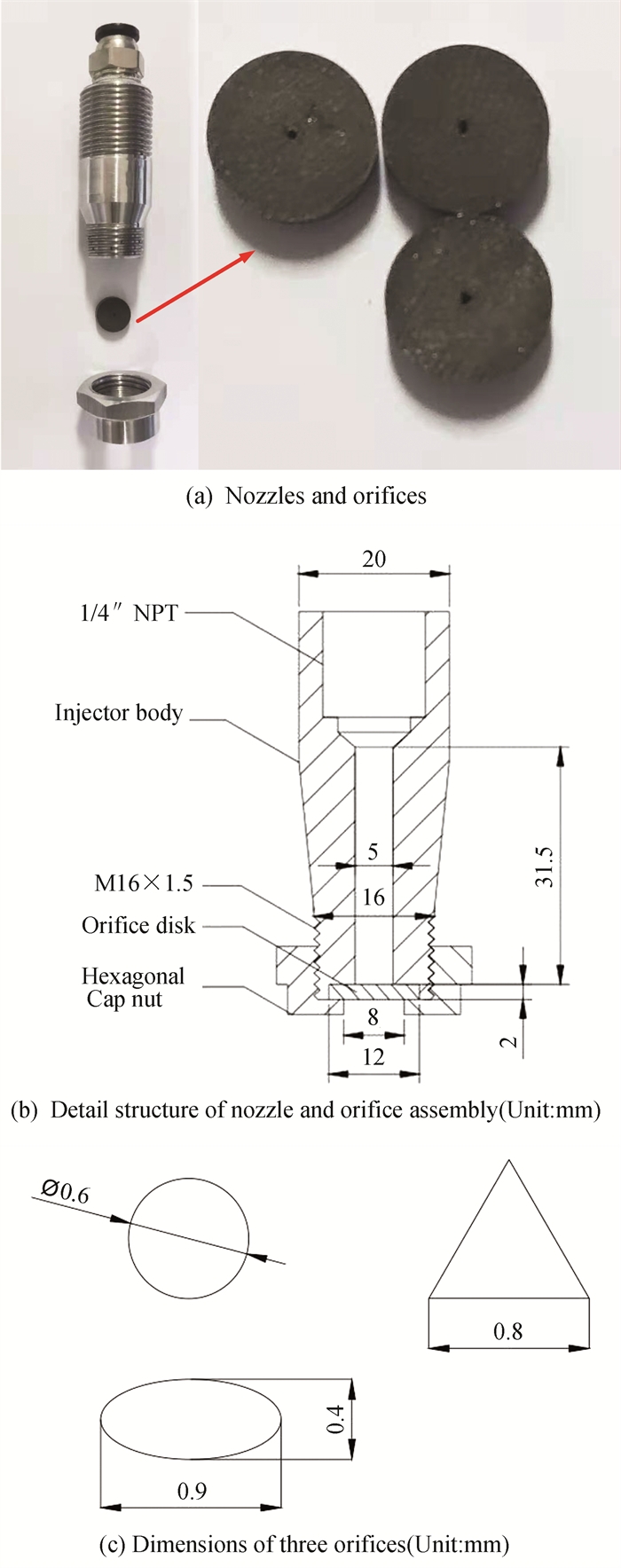
The experiments used specially designed circular and non-circular nozzles. Figs. 2(a) and 2(b) illustrate the detailed construction of the nozzle and the orifice assembly drawing. The injector has only one orifice in the axial direction. All these orifices, including round, triangular and oval geometriesㄛare machined with a wire cutting process. The dimensions of these orifices are given in Fig. 2(c). The cross-sectional areas of all nozzle orifices are consistent so as to be free from geometry effects. The geometrical details of nozzle orifices are shown in Table 1. In particular, the triangular orifice is an equilateral triangular orifice with a side length of 0.8 mm.
|
Fig.2 Structure of nozzles and dimensions of three orifices |
| Table 1 Geometrical details of three different orifices |
The flow field information of the spray can be obtained by processing the image. The tracer particles added to the fluid follow the movement of the fluid, and the laser light source illuminates the flow field. Then the invisible flow field can be visualized as countless discrete bright spots. The CCD camera captures and records the instantaneous position of the tracer particles in the flow field space twice (at t1, t2, time interval Δt). After image processing, the corresponding tracer particles on the two frames of images are identified. The displacement of the tracer velocity vector can be computed by cross-correlation analysis.
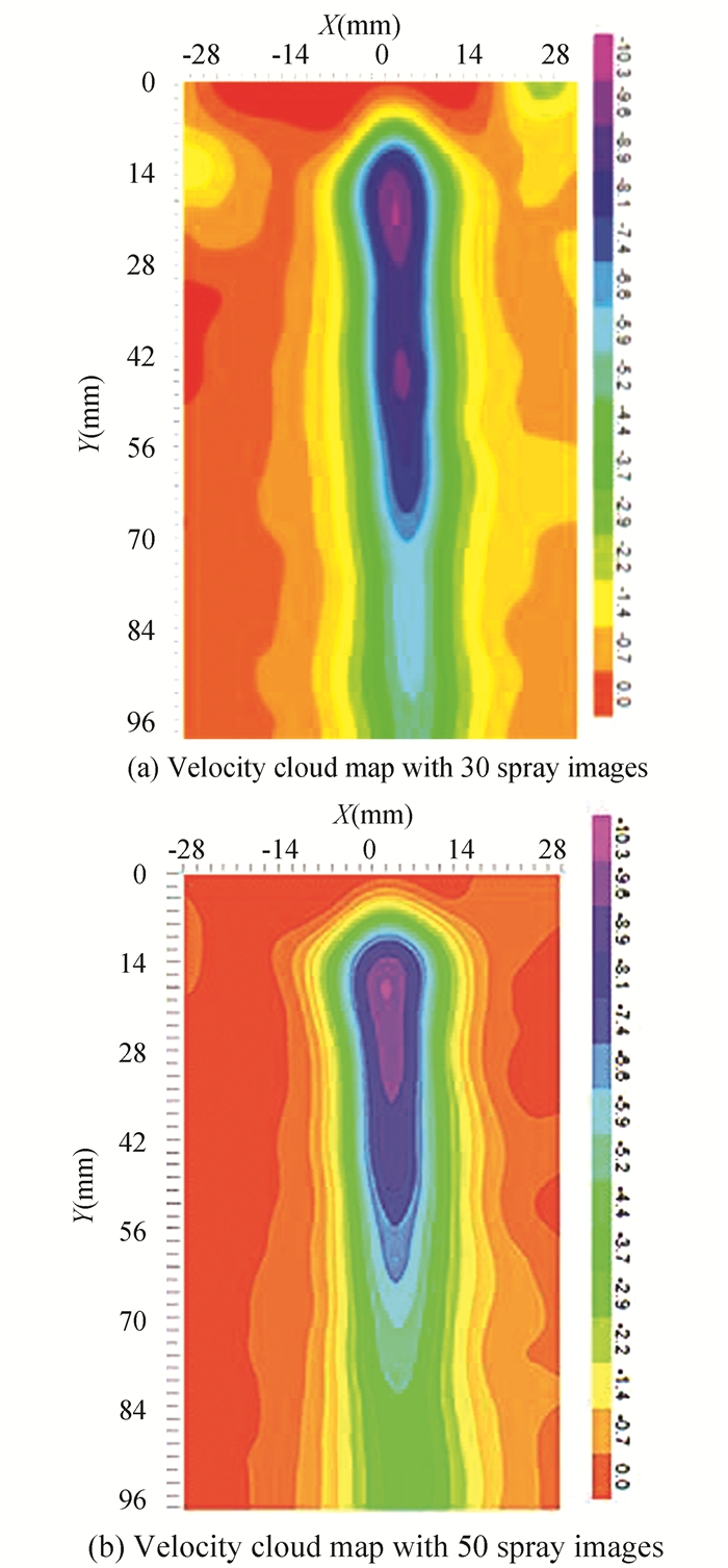
In the process of dealing with the data of spray velocity field, according to experience, the larger the amount of data processed, the faster the velocity cloud map can reflect the movement of droplets. However, the amount of experimental data is very large. In order to accurately obtain the flow field information and reduce the workload of post-processing, it is necessary to carry out pre-test comparison to determine an appropriate number of samples. As shown in Fig. 3, 30 spray images and 50 spray pictures were selected respectively. After processing, the time averaged velocity images obtained from 50 images were compared with those obtained from 30 spray images, and the velocity field of the cloud map images was more continuous and smoother, and the mainstream area was more obvious and symmetrical. The time averaged velocity has obvious gradient in radial and axial direction, which makes it easier to explore and analyze the subsequent spray velocity law.
|
Fig.3 Average velocity cloud map of flow field |
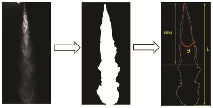
The spray images were processed by MATLAB software. Image binarization processing was first carried out, and then the boundary was detected. Fig. 4 illustrates the way of determining the spray cone angle, where L is the penetration distance of the spray tip, θ is the spray cone angle. In this paper, the angle formed by the connection between the apex of the spray hole and the two points with 60% spray penetration at the edge of the spray jet were used[13]. In order to accurately obtain spray characteristics, for each working condition, 10 spray images were selected to calculate the average value.
|
Fig.4 Schematic diagram of spray penetration distance and spray cone angle |
2 Results and Discussions 2.1 Influence of Liquid Injection Rate and Air Pressure on Spray Angle
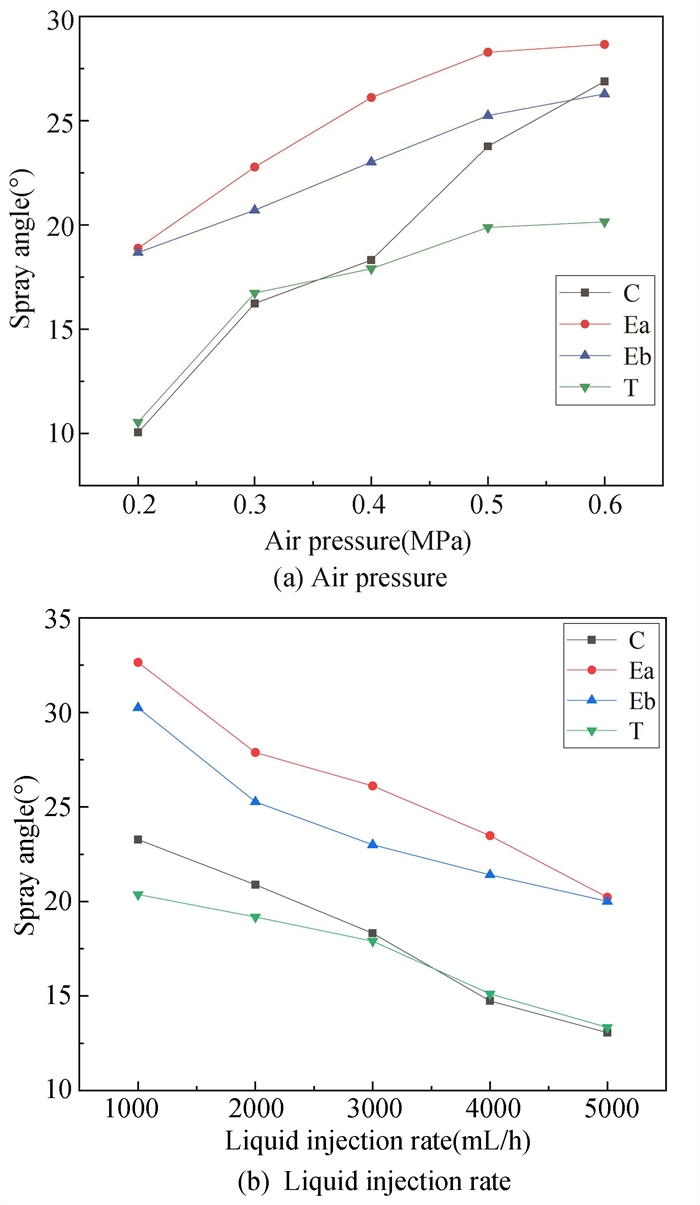
Fig. 5 shows the development process of the spray cone angle of circular, triangular and elliptical nozzles with the change of air pressure and liquid injection rate. An illustrative pattern of the development of the spray cone angle in the primary and secondary planes is described, and three different shapes of nozzle holes, circular, elliptical and triangular, are compared. For triangular orifice, the measured plane is the place where the height of the triangle lies. In Fig. 5, the primary and secondary planes are denoted as “Ea” and ”Eb”, ”C” means circular orifice, and ”T” indicates triangular orifice. As shown in Fig. 5(a), the spray cone angle increases with air pressure for all geometrical orifices under constant liquid injection rate. This is because when the ambient air pressure increases, the interaction between air and water becomes more intensive. It can also be seen from the curve changes on the graph that the spray cone angle in the main plane of the elliptical orifice is larger than the spray cone angle in the secondary plane. Table 1 shows that the diameter of the circular hole is larger than the minor axis dimension of the elliptical hole. However, the spray cone angle of the circular orifice is smaller than that of the secondary plane of the elliptical orifice. This is because the elliptical holes shift in the process of spray development. The spray cone angle of the triangular orifice is the smallest. The reason is that the hydraulic diameter of triangle is the smallest. With air pressure of 0.2 MPa, it can be found that the circular orifice and triangular orifice have the smallest spray cone angle. This is because there is no complete atomization under the working condition. The result also indicates that the elliptical orifice gives better atomization performance even under low air pressure conditions. When the air pressure ascended to 0.3 MPa, the spray cone angles of both of orifices increases rapidly, which indicates that the mixing quality of air and water is greatly improved. As air pressure increases, the size of spray cone angle of the circle becomes closer to that of elliptical, while the spray cone angle of a triangular orifice is not much affected by air pressure. In addition, it can be seen that the air pressure is from 0.5 MPa to 0.6 MPa, which is only slightly increased compared with that in the previous air pressure change process. A possible explanation is that air and water are blended in the closed space of the atomizer, and as the air pressure increases, the air density increases, so the liquid is subject to an increase in the oder resistance.
|
Fig.5 Influence of air pressure and liquid injection rate on the spray cone angle |
It can be concluded from Fig. 5(b) that when the ambient pressure is constant, the spray cone angle tends to decline, the liquid injection increases, the increase of liquid injection rate weakens the interaction between air and water and reduces the resistance of liquid movement. In other words, the air cannot completely atomize the water, and as the water injection rate increases, the atomization quality deteriorates. The spray angle of triangular orifice still does not show vigorous effect on spray cone angle under all test conditions. For elliptical orifice, the spray cone angle is always greater than circular orifice and triangular orifice even at a higher liquid injection rate. The main reason is that the spray cross-section of the elliptical nozzle is larger, because the interaction between elliptical spray droplets and gas is more obvious, which leads to the increase of elliptical spray cone angle. It is also demonstrated that the elliptical orifice provides better atomization performance due to its axis-switching phenomenon. In practical applications, it is essential to take the atomization quality of the droplets into account to prevent droplets from hitting the wall. The non-circular orifice shows better spray characteristics, but may cause impingement. Therefore, it is necessary to select the appropriate orifice according to the diameter of the exhaust pipe.
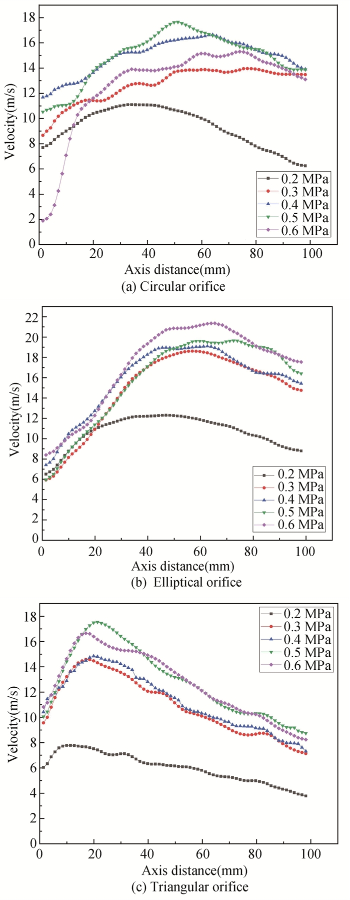
2.2 Influence of Liquid Injection Rate and Air Pressure on Velocity FieldFig. 6 depicts the variation of the velocity field along the axis for the three spray holes with increasing spray distance under 3000 mL/h injection volume and different air pressures. For all three spray holes, it can be observed that the injection speeds first increase and then decrease in the axial direction. After the atomized droplets leave the nozzle outlet, they lack external force and are affected by air resistance and the interaction between droplets. The acceleration of the droplets gradually decreases, causing the droplet velocity to increase first and then decrease. The results show that, at the same spray distance, when the air pressure increases, and the axial spray velocity of the circular orifice first increases and then decreases. In particular, in the low pressure region, the spray rate tends to increase with pressure; however, the spray velocity decreases when the air pressure reaches 0.6 MPa. The triangular orifice has the same phenomenon as the circular orifice. According to Kim and Lee[14], under the test condition, there is an annular flow in the nozzle, the gas occupies the middle of the nozzle hole to form a gas column, and the liquid phase circulars surrounds the inner wall of the nozzle to form a ring-shaped liquid film. Before the gas and liquid are ejected, the mixing process is accompanied by violent interaction, which increases the surface energy of the liquid; when the gas reaches the nozzle outlet, because the ambient pressure is lower than the internal pressure of the nozzle, the gas further expands and accelerates, and the relative velocity between the droplet and the gas is high. Therefore, increasing the air pressure will make the interaction between air and water stronger at the same injection rate. The strong movement of air and water leads to more thorough mixing between air and water, and the relative velocity between air and water also increases. However, the gas and liquid mixed in the confined space of the atomizer, and when the air pressure reaches 0.6 MPa, the flow resistance of the liquid increases. In addition, the mixture of water and air is ejected from the nozzle without sufficient mixing on account of the rapid flow of air, and the compressed air does not provide sufficient energy for the water, which in turn decreases the injection speed of the circular and triangular orifices. As a comparison, the injection velocity of the elliptical orifice increases in accordance with the air pressure. What is more, the elliptical orifice gives the largest velocity at all conditions. That can be interpreted that the axis-switching makes the flow instability at the interface increases, which can significantly improve the mixing quality. When the air pressure is 0.2 MPa, the velocity of orifices is minimum, which may be attributed to the fact that the gas does not completely atomize so much water, resulting in a jet in the process.
|
Fig.6 Distribution of axis velocity under constant liquid injection rate |
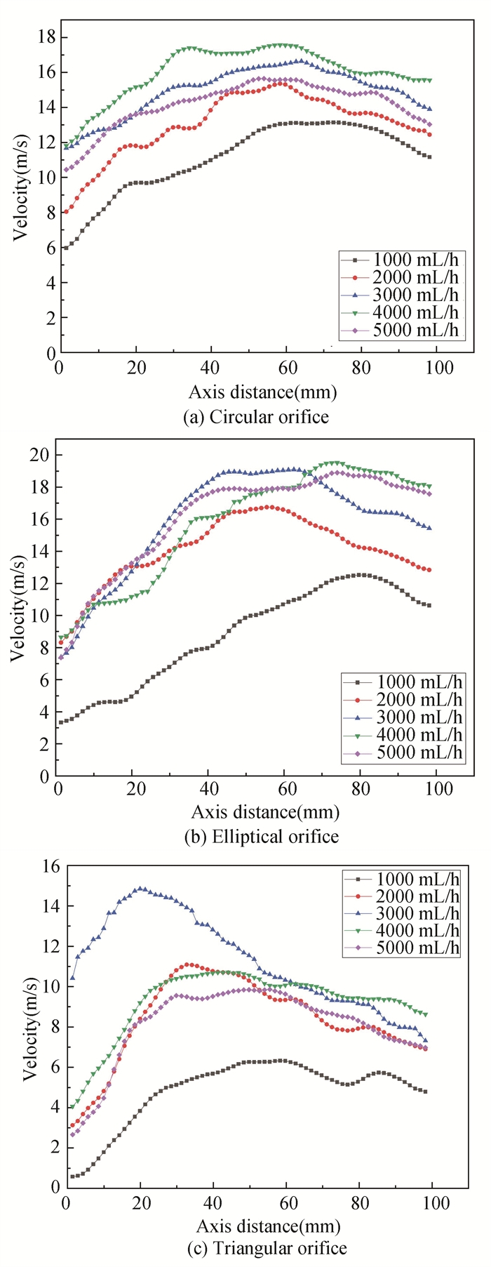
The variation tendency of velocity with the liquid injection rate at air pressure of 0.4 MPa is shown in Fig. 7. The injection rate of the circular hole grows as the fluid injection rate rises until the liquid injection rate reaches 4000 mL/h. As mentioned above, when the gas and liquid move to the nozzle outlet, increasing liquid injection rate can promote the air pressure and the relative velocity between the gas and the liquid. Therefore, the axis velocity gets an increase. However, when the liquid injection rate reaches 5000 mL/h, the liquid occupies more position, and the 0.4 MPa air pressure is unable to fully atomize so much water, which finally causes the liquid jet and makes the velocity decrease. For elliptical orifice, the velocities at 3000-5000 mL/h are very close. It is indicated that under constant air pressure, an elliptical orifice can increase liquid rate, but it cannot greatly increase the velocity. Additionally, the speed of elliptical nozzle is faster than that of circular nozzle and triangular nozzle, which can be predicted. As mentioned before, it can be attributed to axis-switching. As shown in Fig. 7(c) 3000 mL/h liquid injection rates is the best condition for triangular orifice. Triangular orifice reaches the maximum fastest compared to circular orifices and elliptical orifices. The velocity decay rate is the largest; therefore, its mixing efficiency may be higher, which also can be drawn from Fig. 5.
|
Fig.7 Distribution of axis velocity under constant air pressure with different liquid injection rates |
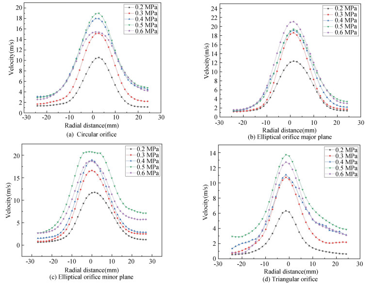
The spray velocity distribution at a cross-sectional distance of 44 mm from the nebulizer at a liquid injection rate of 3000 mL/h and at various air pressures is represented in Fig. 8. As a whole, the velocity of the flow field shows a trend of first increasing and then decreasing. The changing trends of the curves are similar under each condition, indicating that the change of air pressure does not have much influence on the overall velocity distribution trend of the flow field. It can be seen that the maximum velocity appears near the axis, but not exactly on the axis. Moreover, the curves are not symmetrical completely. It is evident that the droplets are affected by air turbulence and evaporate during the movement, and collisions between droplets will cause the droplets to continue to break up or aggregate. In the radially outlying area, the speed distribution curves at different conditions almost overlap. This indicates that the lower the droplet velocity in the radial region isaway from the nozzle, and the weaker the droplet diffusion ability is in the radial direction. It can also be found that when the air pressure is low, increasing air pressure brings apparent changes.In contrast, with the increasing air pressure, changes only occur near the axis. Take the circular orifice as an example, when the pressure increases from 0.2 to 0.3 MPa, almost all points on the curve move upwards.However, when the pressure increases from 0.4 to 0.5 MPa, only the points close to the axis change. Here, it shows that the increase in air pressure will weaken the radial diffusion. On the other hand, the air current mainly increases the velocity of droplets in the axial direction. For elliptical orifice, with a pressure of 0.3 MPa, the velocity reaches 18 m/s, which is better than circular orifice and triangular orifice; however, increasing the air pressure velocitydoes not show evident variety. As shown in Fig. 8(d), the spray velocity of triangle orifice at the cross section is more chaotic than that of the circular orifice and the elliptical orifice. This may be due to the acute angle of triangular orifice.[15].
|
Fig.8 Distance from orifice to the cross section is 44 mm, and the speed at different air pressures |
Under the 0.4 MPa liquid injection rate and different liquid injection rates, the spray velocity distribution on the cross section at 44 mm from the sprayer is depicted in Fig. 9. The velocity development trend of the flow field is consistent with the previous description. Intersections occur between the curves corresponding to each condition.Specifically the fluid injection ratesare 2000 mL/h, 3000 mL/h, and 4000 mL/h. It is indicated that in the case of good atomization, increasing the liquid injection rate has no outstanding effect on increasing the spray velocity.

|
Fig.9 Distance from orifice to the cross section is 44 mm, and the velocity at different liquid injection rates |
2.3 Influence of Liquid Injection Rate and Air Pressure on Droplet Diameter
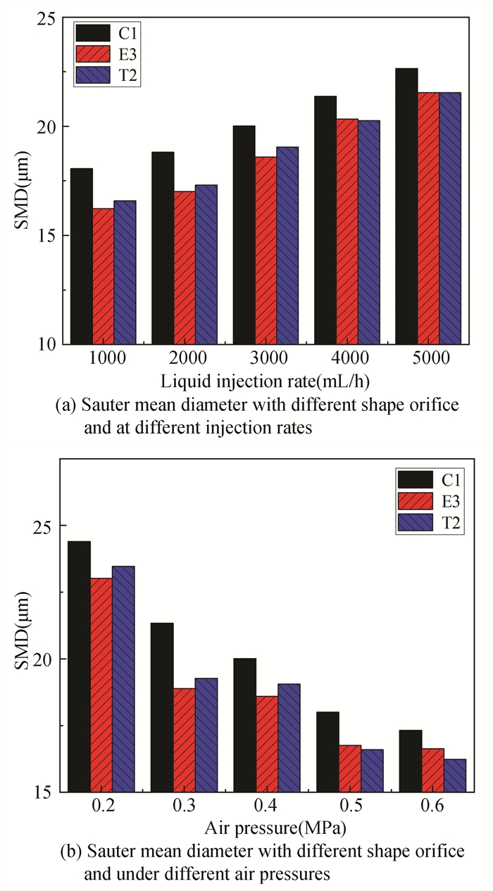
The particle size distribution at 50 mm from the nozzle outlet was measured, as shown in Fig. 10. The graph shows that as the injection rate increases or the air pressure decreases, the Sauter mean diameter at the outlet of each type of orifice increases. When the injection rate increases, the required amount of auxiliary air decreases, resulting in the weakening of the purging effect of compressed air, the gas cannot atomize more water, and the atomization quality becomes worse; under aconstant injection rate and increasing injection pressure, the gas column formed in the nozzle extrudes the liquid film, which makes it thinner. Furthermore, the increase of injection pressure improves the energy obtained when the liquid film is broken, which makes the droplets easier to break into smaller droplets.
|
Fig.10 SMD of different orifice with same outlet area under various working parameters |
From the theory of droplet breakup, the breakup of droplets in spray flow is determined by the internal and external factors of droplets. For a small viscosity fluidㄛthe ratio of surface tension to droplet size is an important parameter The ratio of aerodynamic force to this parameter is similar to that of Weber Number (We):
| $ \mathrm{We}=\frac{\rho_g u_d^2 D}{\sigma} $ | (1) |
where ud is the velocity difference of gas and liquid(m/s). In Eq.(1), the larger the ratio of aerodynamic force to surface tension is, the larger the Weber number is, and the easier the droplet is to break. The critical condition of droplet breakup is as follows:
| $ \frac{C_D}{8} \rho_g u_d^2=\frac{\sigma}{D} $ | (2) |
where CD is a constant depending on the fragmentation condition. It can be seen from Eq.(2) that when the droplet is broken, when the injection amount remains unchanged and the injection pressure increases, the gas momentum increases, the gas flow rate becomes faster, and the liquid surface tension remains unchanged, thus the droplet diameter decreases and the atomization effect improves.
In addition, non-circular orifices can promote the breakup of droplets to a certain extent. When the injection rate is less than 3000 mL/h, compared with the SMD of equilateral triangular orifice, the SMD of circular orifice is 8% larger. This is because when the injection rate is small, the corner of equilateral triangle nozzle is sharper, so the liquid film at the corner is thinner, forming an unstable shear wave. The gas-liquid interaction is enhanced, and it is easier to break into smaller droplets, which will strengthen the atomization effect. The Sauter average diameter is smaller, which is called the corner effect. When the injection rate increases, the difference between the two orifices droplet Sauter mean diameter decreases. This is because when the injection rate is large, most of the droplets from the equilateral triangle nozzle exit eject from the center of the nozzle, and the corner effect weakens, which leads to poor atomization quality. Therefore, compared with the circular nozzle, the advantage is not obvious. When the injection rate is small, the SMD of the elliptical nozzle is 10% smaller than that of the droplet outlet of the circular nozzle. Similarly, when the injection volume increases, the particle size difference between elliptical hole and circular hole also decreases. When the injection volume reaches 5000 mL/h, the average diameter of the droplet of the elliptical hole is almost the same as that of the equilateral triangle, and it is always smaller than the circular hole. This is because the axial transformation occurs in the elliptical spray. The shaft transition phenomenon is the interlocking of the long axis and the short axis surface of the elliptical nozzle in the atomization process, i.e., the ellipse spray experienced a shaft changing during the spray process. Under the influence of external factors, the droplet surface will oscillate, and the vibration frequency is:
| $ \omega^2=\frac{2 \sigma n(n-1)(n+1)(n+2)}{{\rm{ \mathsf{π} }}^2 D^3\left[\rho_l(n+1)+\rho_g n\right]} $ | (3) |
where n is a constant. When the air disturbance is relatively stable during crushing, the vibration produced by the droplet is also small. When n = 2, the gas density can be ignored in most cases. The phenomenon of axis conversion of elliptical nozzle increases the instability of the liquid outlet, which leads to the increase of the vibration frequency of the droplet and further aggravates the fragmentation of the droplet. Therefore, this phenomenon makes the droplet surface from the elliptical nozzle vibrate more frequently during the atomization process, which intensifies the fragmentation of the droplet and improves the atomization.
The droplet Sauter mean diameter of the nozzles of each shape decreases greatly during the pressure from 0.2 MPa to 0.3 MPa, as shown in Fig. 10(a).However, the SMD reduction for non-circular orifices is greater than that for circular orifices.In addition, it is also noted that when the injection pressure increases from 0.3 MPa to 0.4 MPa, the drop Sauter average diameter of different nozzle shapes decrease slightly, and the non-circular nozzle is more obvious. However, the injection pressure continues to increase to 0.5 MPa, and the decrease of SMD of different shapes nozzles increases again. The decrease of Sauter average diameter of circular nozzle C1, equilateral triangle nozzle T2 and elliptical nozzle E3 is about 10%, 11% and 13% respectively. When the injection pressure keeps growing up to 0.6 MPa, the Sauter mean diameter almost does not change. This shows that for equilateral triangular nozzle and elliptical nozzle, the corner effect and axis conversion phenomenon are the keys to improve the atomization quality, and after the axis conversion phenomenon occurs, the improvement of atomization quality by increasing the injection pressure is not great compared with that of circular nozzle. However, it can also be found that when the injection pressure is lower than 0.5 MPa, the average diameter of the elliptical nozzle is larger than that of equilateral triangular nozzle, but when the injection pressure increases, the situation is on the opposite. This may be because when the injection pressure goes up, the equilateral triangular nozzle not only has corner effect, but also has axis conversion.The combination of the two makes the droplet shape more chaotic, the vibration frequency increase, and the crushing effect better.
3 ConclusionsIn this paper, the spray cone angle, the Sauter mean diameter and the velocity field of non-circular orifices in an air-assisted system are investigated by using the PIV technique and laser particle size analyzer under various air pressures (0.2 -0.6 MPa) and liquid injection rates (1000-5000 mL/h). The following conclusions are obtained:
1) Under most air pressures and liquid injection rates, the spray cone angles of the elliptical nozzle on the main plane and the secondary plane are larger than those of the circular nozzle and the triangular nozzle. As the hydraulic diameter is small, the spray cone angle of triangular nozzle is the smallest. During the process of spray development, the elliptical nozzle has a larger spray cone angle because of its fast fuel crushing and atomization speed. With the development of spray, the force between ambient air and liquid becomes larger, the oil-gas contact area gradually increases, and the air resistance of elliptical nozzle is larger than that of circular nozzle. Consequently, the penetration ability of spray decreases and the spray cone angle increases.
2) Although the diameter of the circular orifice is longer than the minor axis of the elliptical orifice, the spray cone angle of the circular orifice is smaller than that of the elliptical orifice in the minor plane. This result indicates that the elliptical spray exhibits axis-switching phenomenon during the injection process. The frequency of axial switching rises with increasing injection pressure, the primary reason is that the increase in injection pressure results in unstable fluctuations and deformation of the spray.
3) In the axis, the spray velocities of the elliptical orifice are the largest under most of the working conditions, and the spray velocities of the triangular orifice is the fastest to reach the maximum and the velocity decays the fastest, which means that the mixing efficiency would be presumably higher. Considering the non-axial symmetry of triangular nozzle spray, the spray cone angles of triangular nozzle alternate on the long-axis plane and the short-axis plane, which indicates that the triangular spray has experienced axis change. The phenomenon of axis-switching is beneficial to entrainment effect, which facilitates gas-liquid mixing.
4) In the axis, within a certain range, as the air pressure and liquid injection rate increase, the injection rate of the three holes also increases. The elliptical orifice is proved to generate great spray velocity even during the poor atomization performance. Increasing injection pressure combined with triangular injection holes can effectively improve the quality of atomization and gas-liquid mixing.
5) In the radial, increasing the air pressure will weaken the spread in radial. Increasing the liquid injection rate has no illustrious effect on increasing the spray velocity.
6) For the nozzle with different shape and equal outlet area, the atomization effect can be improved by increasing the spray pressure or reducing the spray amount. Non-circular nozzle has a certain promotion effect on the droplet breakage and can improve the atomization condition.
| [1] |
Hu J C, Liu B L, Zhang C, et al. Experimental study on the spray characteristics of an air-assisted fuel injection system using kerosene and gasoline. Fuel, 2019, 235: 782-794. DOI:10.1016/j.fuel.2018.08.083 (  0) 0) |
| [2] |
Liao Y J, Eggenschwiler P D, Rentsch D, et al. Characterization of the urea-water spray impingement in diesel selective catalytic reduction systems. Applied Energy, 2017, 205: 964-975. DOI:10.1016/j.apenergy.2017.08.088 (  0) 0) |
| [3] |
Ma R, Dong B, Yu Z Q, et al. An experimental study on the spray characteristics of the air-blast atomizer. Applied Thermal Engineering, 2015, 88: 149-156. DOI:10.1016/j.applthermaleng.2014.11.068 (  0) 0) |
| [4] |
Kasyap T V, Sivakumar A, Raghunandan B N. Breakup of liquid jets emanating from elliptical orifices at low flow conditions. Atomization and Sprays, 2008, 18(7): 645-668. DOI:10.1615/AtomizSpr.v18.i7.30 (  0) 0) |
| [5] |
Kasyap T V, Sivakumar D, Raghunandan B N. Flow and breakup characteristics of elliptical liquid jets. International Journal of Multiphase Flow, 2009, 35(1): 8-19. DOI:10.1016/j.ijmultiphaseflow.2008.09.002 (  0) 0) |
| [6] |
Wang F J, Fang T G. Liquid jet breakup for non-circular orifices under low pressures. International Journal of Multiphase Flow, 2015, 72: 248-262. DOI:10.1016/j.ijmultiphaseflow.2015.02.015 (  0) 0) |
| [7] |
Amini G, Dolatabadi A. Axis-switching and breakup of low-speed elliptic liquid jets. International Journal of Multiphase Flow, 2012, 42: 96-103. DOI:10.1016/j.ijmultiphaseflow.2012.02.001 (  0) 0) |
| [8] |
Messina T, Acharya S. Characteristics of an acoustically modulated spray issued from circular and elliptical orifice nozzles. Atomization and Sprays, 2006, 16(3): 331-348. DOI:10.1615/AtomizSpr.v16.i3.60 (  0) 0) |
| [9] |
Mi J, Nathan G J, Luxton R E. Centreline mixing characteristics of jets from nine differently shaped nozzles. Experiments in Fluids, 2000, 28(1): 93-94. DOI:10.1007/s003480050012 (  0) 0) |
| [10] |
Quinn W R. Measurements in the near flow field of an isosceles triangular turbulent free jet. Experiments in Fluids, 2005, 39(1): 111-126. DOI:10.1007/s00348-005-0988-2 (  0) 0) |
| [11] |
Azad M, Quinn W R, Groulx D. Mixing in turbulent free jets issuing from isosceles triangular orifices with different apex angles. Experimental Thermal and Fluid Science, 2012, 39: 237-251. DOI:10.1016/j.expthermflusci.2012.01.028 (  0) 0) |
| [12] |
Hashiehbaf A, Romano G P. Particle image velocimetry investigation on mixing enhancement of non-circular sharp edge nozzles. International Journal of Heat and Fluid Flow, 2013, 44: 208-221. DOI:10.1016/j.ijheatfluidflow.2013.05.017 (  0) 0) |
| [13] |
Du B G, Long W Q, Feng L Y, et al. Study on multi-piece spray characteristics based on Matlab digital image processing technology. Chinese Internal Combustion Engine Engineering, 2008, 29(4): 1-5. DOI:10.13949/j.cnki.nrjgc.2008.04.006 (  0) 0) |
| [14] |
Kim J Y, Lee S Y. Dependence of spraying performance on the internal flow pattern in effervescent atomizers. Atomization and Sprays, 2001, 11(6): 735-756. DOI:10.1615/AtomizSpr.v11.i6.80 (  0) 0) |
| [15] |
Sharma P, Fang T. Breakup of liquid jets from non-circular orifices. Experiments in Fluids, 2014, 55(2): 1666-1-1666-17. DOI:10.1007/s00348-014-1666-z (  0) 0) |
 2023, Vol. 30


