2. Department of Fashion Technology, National Institute of Fashion Technology, New Delhi-11016, India
Onyx-glass which is a composite material used in aerospace, robotics, structural, automobile applications etc., has unique properties namely higher stiffness, less weight, resistance to corrosion, low thermal expansion and high strength[1]. Nowadays, with the help of additive manufacturing near net shaped fiber reinforced polymer (FRP) composite materials are processed[2-4]. Frequently, the machining operations (drilling) are required for assembling the components within mechanical structures. Moreover, additively manufactured (AM) parts have poor surface roughness and improper dimensional tolerances. Because of this, additional machining operations (drilling) are needed for the printed parts[5].
The fabrication of composite materials through conventional method undergoes a lot of limitations because of impact loadings and compressive loadings. Moreover, due to impact loading, composite materials undergo failures such as intralaminar matrix cracking, splitting, fiber matrix incomplete bonding, delamination, longitudinal matrix splitting and fiber pull out etc.[6-8] For composite materials manufacturing, mostly carbon fiber is utilized due to its stiffness, high strength, high specific modulus and lower density[4]. Composite materials during machining undergo delamination, and the inner layers are exposed to various harmful effects. In the current scenario, significant challenge lies during the drilling of polymer composite materials. Abrao et al.[9-11]observed that the severe delamination of fiber-reinforced composite materials during drilling was due to the higher surface roughness values that affects the machinability of composites.
Tan et al.[12]investigated the machining process parameters which were analyzed through statistical analysis using Taguchi method for the minimization of surface roughness and delamination. The conventional method of machining for the polymer matrix composite materials has one of the drawbacks which results in pragmatic poor surface quality because of diversification of the composite materials. In addition to fiber matrix de-bonding as a result of deprived surface roughness, fiber inter-laminar delamination led to crack initiation and crack propagation as reported by Heidary et al.[13] During drilling, FRP composite materials are facing the major issues such as fiber pull out, burr formation, spalling, fuzzing, cracking, poor surface roughness, delamination and thermal degradation. The machinability studies were reviewed by Unde et al. [14] for FRP composite materials through the AWJM method. It was stated that abrasive mass flow rate, transverse speed, standoff distance and water jet pressure are the most influencing parameters for the machining of FRP composite materials. FRP composite materials are machined using AWJM due to the absence of heat affected zone, which is the primary cause of thermal distortion. Shaikh et al.[15] investigated the mechanism of cutting cotton fiber polyester FRP composite materials using diamond saw cutting, CO2 laser and water jet cutting methods. From the experimental analysis, it was established that laser cutting was preferred than diamond saw cutting and water jet cutting because of fiber pull-out in composite materials. Ramulu et al.[16] studied the machinability studies on graphite-epoxy composite materials using the AWJM and water jet machining (WJM). It was observed that AWJM showed better surface finish than WJM. The AWJM process showed better performance in the presence of abrasive particles, because the removal mechanisms were based on micromachining, erosion and shearing. Jani et al.[17] reported the drilling of hemp-Kevlar/epoxy (hybrid composite materials) using the AWJM. It was concluded that among the various machining process parameters, the transverse speed will determine better surface finish of the hybrid composite materials. Dubey et al.[18] stated that the recently developed algorithms HSA, WOA and GWOA outperform other metaheuristics. They have been used to resolve an assortment of real-life optimization problems because they help to validate the results in extensive experimentation.
When compared with conventional machining methods, issues pertaining to machining of FRP composite materials can be reduced through AWJM as reported by Ramesha and Akhtar [19]. The process of drilling using AWJM is free from thrust force (TF), generation of chip, plastic delamination and cutting tool as stated by Prabu et al. [20] The different types of AM techniques which are developed in the industry were fused deposition modeling (FDM), selective laser sintering (SLS), stereo-lithography apparatus (SLA), direct metal deposition (DMD), direct inkjet printing (DIP), selective laser melting (SLM)and laminated object manufacturing (LOM). These methods are differing from each other in the approach of layer deposition and also in the types of materials used for the fabrication process [21-24]. Whereas, FDM is the most adaptable AM process that provides serviceable and prototype components in various thermoplastic and polymeric materials as it can produce complex geometrical parts at low cost with good recyclable value. Further, the internal surfaces of AM parts are subjected to post processing as it consists of porosity, poor surface finish and voids[25]. The internal surfaces of AM parts cannot be machined through conventional methods. To make the smoothening of the internal surfaces, the unconventional methods are most suitable, such as water jet machining, Electrical Discharge Machining (EDM), abrasive flow jet machining, ultrasonic machining and AWJM. Among these methods, the AWJM process is environmentally friendly and less expensive.When compared to other techniques, AWJM has negligible thermal deformation, no change in physical and chemical properties, less chemical contamination and no need for cutting fluid[26].
The Mark forged 3D printer-FDM can make a hole with near net-shape. Even though the quality of the 3D printed components is good, the uniformity of the surface roughness is not maintained throughout. Moreover, to obtain accurate dimensions of hole is a daunting task. Abdulhameed[27], Pal[28], Atzeni[29] and Khorasani[25] reported that 3D printed parts have poor surface roughness, dimensional inaccuracy and warping. Because of that, the present study is primarily focused on machinability studies on 3D printed parts of onyx polymer composites using AWJM. Moreover, it is challenging to minimize delamination defects and lower surface roughness in the FRP composite materials followed by the conventional machining process. In order to overcome these drawbacks, the unconventional machining process AWJM was used to minimize these defects.
Based on the pertinent literature survey on AWJ drilling of FRP composite materials, it can be concluded that there is no intelligence presented on 3D printed parts of Onyx-Glass fiber Hybrid Composites(OGFHPC) machinability studies through AWJ drilling technique. Therefore, in this study, the AWJ drilling process parameters such as abrasive mass flow rates, drilling diameters and traverse speed were optimized by Taguchi method of the OGFHPC at constant abrasive water jet pressure and standoff distance.
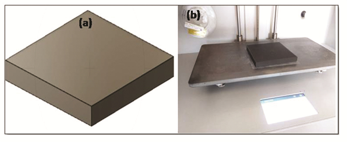
1 Materials and Methods 1.1 Onyx-Glass Polymer CompositeThe Onyx with reinforcement of glass fiber was used as a raw material in the present study. The raw material used was of filament type with combination of onyx 50% and reinforcement of glass fiber 50%. The printing process parameters of onyx-glass were set to be of a total number of 100 layers with rectangular solid fill pattern, in which the thickness of each layer was maintained at 0.1 mm and the infill density was set to be 100%. The design of OGFHPC was modeled with computer-aided design (CAD) solid works software version 18.0, as shown in Fig. 1 (a). The OGFHPC was fabricated with Mark forged (USA) Mark Two Desktop composite 3D printer, as shown in Fig. 1(b), and printed through fused deposition modeling method. Among the various additive manufacturing methods, fused filament fabrication technique is low cost, energy savings and fast with minimal wastage. The dimensions of printed OGFHPC are 100 mm×100 mm×10 mm, as shown in Fig. 1 (b). The printed OGFHPC sample hardness was measured using a durometer shore D hardness as per ASTM D 2240 standard. Hardness measurements were carried out ten times for repeatability and a hardness value of 72 shore D was reported.
|
Fig.1 Onyx-glass fiber Mark forged Mark Two Desktop composite 3D printers - Experimental setup (a) Onyx-glass CAD model, (b) Printed onyx-glass fiber hybrid polymer composite sample |
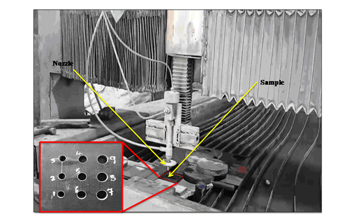
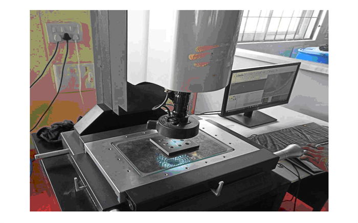
The drilling was performed on printed OGFHPC using AWJM is shown in Fig. 2. The AWJM travel capacity is 3500 mm on X-axis and 1500 mm on Y-axis. The constant machining parameters of AWJ as shown in Table 1. The AWJM process has many advantages such as low cutting force, high flexibility, no heat affected zone, no residual stress formation, eco-friendliness, ability to generate complex shapes and high machining performance. Therefore, residual stress is not formed during the AWJ drilling of onyx composite (3D printed sample). Moreover in AWJM method, mechanical properties of the component are retained due to the non-contact of the tool with the work piece[30]. The delamination of the entry hole and exit was measured by using the Optical based 2D-Profile projector vision measuring machine, as shown in Fig. 3. The delamination factor (Fd) is calculated based on the standard formulae in Eq.(1) [31].
| $ F_{\mathrm{d}}=D_{\max } / D_o $ | (1) |
|
Fig.2 Experimental setup of AWJM for drilling of OGFHPC |
| Table 1 Constant machinability parameters are used for AWJM process |
|
Fig.3 Onyx-glass composite delamination measurement using Optical based 2D-Profile projector vision measuring machine |
where Dmax is maximum diameter of the delaminated region and the Do is the actual diameter of drill hole. The OGFHPC machined area of Dmax is calculated at hole entry and exit using vision measuring machine (VMM) followed by 2D software (MITUTOYO) by implementing three point method. Each reading was repeated five times and average value was noted. The surface roughness was measured using the Contact-type Tomlinson surface meter, as shown in Fig. 4.

|
Fig.4 Contact-type of surface roughness tester |
1.2 AWJM of OGFHPC- Design of Experiments
Literature survey shows that, for the AWJM, Abrasive Water jet pressure, standoff distance, abrasive particle size and nozzle diameter were chosen as process parameters [32]. Design of experiments (DoE) was used for the planning the L9 orthogonal array followed by Taguchi method with nine different combinations of trails[33]. To analyze the process parameters, Minitab '17' software was used for the present study. Three designs of control factors, such as abrasive mass flow rate (AMFR) (g/min), drilling diameter (DD) (mm) and traverse speed (TS) rate (mm/min) with three levels were used, as shown in Table 2. To analyze the optimum possible solutions for the machining process parameters of the OGFHPC, optimization techniques such as the HSA, WOA and GWOA were used. The input parameters used for algorithms as shown in Tables 3-5. These input parameters were chosen based on the literature survey for the HAS, WOA and GWO[34-43].
| Table 2 AWJM process parameters and the levels used for Taguchi Analysis |
| Table 3 Parameters used for HSA |
| Table 4 Various parameters concerned in WOA |
| Table 5 Parameters used for GWO |
2 Results and Discussion 2.1 Effect of AWJM Cutting Parameters on Delamination Factor of OGFHPC
The experimental values of delamination factor both at entry and exit as well as the surface roughness values during AWJ machining of Onyx-Glass polymer Hybrid Composites are shown in Table 6. The Taguchi responses on Signal to Noise ratios (S/N) are chosen as smaller is better for delamination factor at hole entry and exit, as shown in Tables 7 and 8. The S/N ratio is used to calculate the smaller is better as per the standard Eq. (2). Here replication number is denoted by 'n' and the observed response value as 'y'[44].
| $ S / N=-10 \log n^{-1}\left(\sum y^2\right) $ | (2) |
| Table 6 Design of experiments L9 orthogonal array used for Taguchi analysis and measured values for delamination factor (at hole entry and hole exit) and surface roughness |
| Table 7 Delamination factor at hole entry - response table for S/N ratios when smaller is better |
| Table 8 8 Delamination factor at hole exit - response table for S/N ratios when smaller is better |
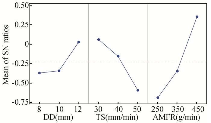
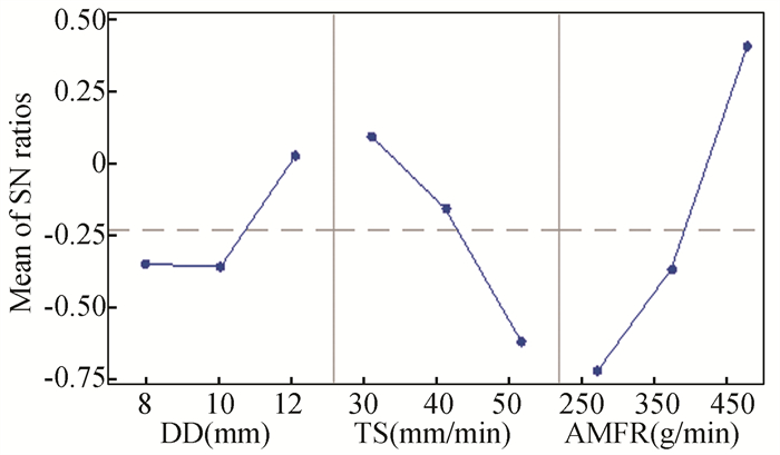
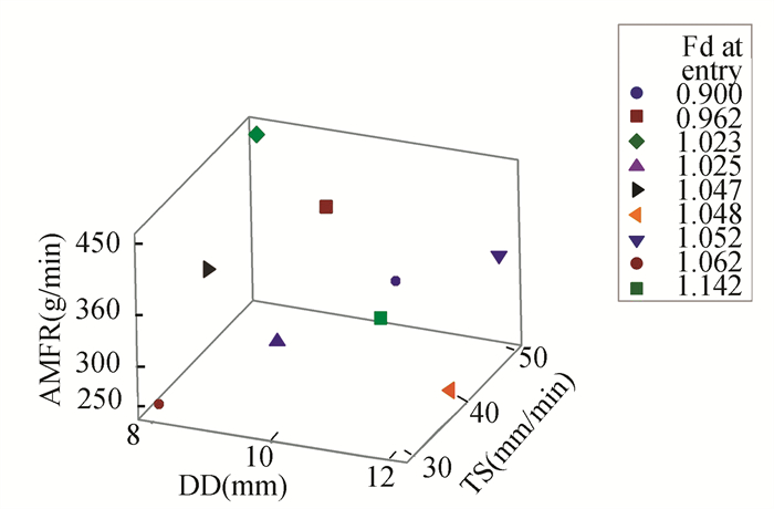
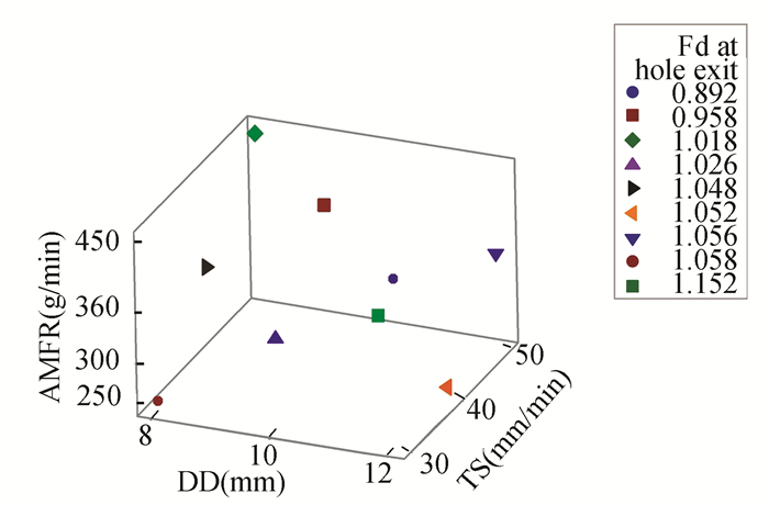
Based on Table 7, the assigned ranking is given by 1.04379, 0.65436 and 0.39612. It can be noted that the influencing factor of AMFR is mainly the traverse speed rate followed by drilling diameter. Figs. 5 and 6 show the Main Effects Plot of S/N ratios on delamination factor at both hole entry and exit. It was obtained that the optimum machining process parameters are level 3 for drilling diameter (12 mm), level 1 for traverse speed rate (30 mm/min) and level 3 for abrasive mass flow rate (450 g/min). Similarly, delamination factor at hole exit is based on the ranking in Table 8, which has been assigned as 1.12217, 0.71144 and 0.38513. It was observed that the AMFR has a major influencing factor than traverse speed rate followed by drilling diameter. The effect of delamination factors at hole entry and exit on AMFR versus TS versus DD are expressed through the 3D scatter response plots in Figs. 7 and 8 respectively. From Figs. 7 and 8, it was observed that the Fd at hole entry and exit decrease gradually in both cases with increasing AMFR and decreasing TS. Because higher abrasive water jet pressure (380 MPa) and AMFR (450 g/min) with lower TS (30 mm/min) lead to increases in the higher momentum of kinetic energy. Delamination is reduced in both cases due to the improved cutting ability. The Kinetic energy is reduced with decrease in AMFR and increase in TS, resulting in higher delamination in both cases. Similarly, in the onyx-glass composite during AWJM, the drilling diameter is major influencing factor to obtain the minimum delamination factor with lower surface roughness. From Figs. 7 and 8, it can be observed that as the drilling diameter increases (8 mm to 12 mm), minimum will be delamination factor at both the entry and exit of hole. Whereas, the lower the drilling diameter of 8 mm and 10 mm, the higher the delamination factor, which cannot be observed at the drilling diameter of 12 mm.
|
Fig.5 Main effects Plot for SN ratios-delamination factor at hole entry(Signal-to-noise: Smaller is better) |
|
Fig.6 Main effects plot for SN ratios-delamination factor at hole exit(Signal-to-noise: Smaller is better) |
|
Fig.7 3D scatter response plot influencing of AMFR vs T.S vs DD on Fd at hole entry |
|
Fig.8 3D scatter response plot influencing of AMFR vs T.S vs DD on Fd at hole exit |
2.2 Effect of AWJM Cutting Parameters on Surface Roughness of OGFHPC
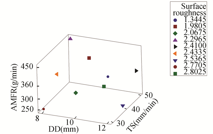
The Taguchi responses on Signal to Noise ratios (S/N) are chosen as smaller is better for surface roughness, as shown in Table 9. The S/N ratio is used to calculate the smaller is better as per the standard Eq. (2). Based on Table 9, ranking has been assigned as 3.386, 2.027and 1.834. It can be noted that the AMFR has a major influencing factor than traverse speed rate followed by drilling diameter. From Fig. 9, the Main Effects Plot of S/N ratio on surface roughness was obtained. The optimum machining process parameters are level 3 of drilling diameter(12 mm), level 1 of traverse speed rate (30 mm/min) and level 3 of abrasive mass flow rate (450 g/min). The effect of surface roughness on AMFR versus TS versus DD is expressed through the 3D scatter response plots of Fig. 10. From Fig. 10, it was noted that the surface roughness decreases gradually in both cases with increasing AMFR and decreasing TS. Because higher abrasive water jet pressure (380 MPa) and AMFR (450 g/min) with lower TS (30 mm/min) lead to increase in higher momentum of kinetic energy, due to that the cutting ability improves along with better surface roughness. Whereas, kinetic energy is reduced with decrease in AMFR and increase in TS, resulting in higher surface roughness. Similarly, the OGFHPC, during AWJM, the drilling diameter is a major influencing factor to obtain the minimum surface roughness. As shown in Fig. 10, it was noted that as drilling diameter increases (8 mm to 12 mm), the surface roughness is minimal. Whereas, the lower the drilling diameter of 8 mm and 10 mm, the higher surface roughness is observed than with the drilling diameter of 12 mm. Cutting actions involves less time due to lower transverse speed and higher AMFR. Moreover, smooth surface roughness is a result of more abrasive particles on the surface.
| Table 9 Response table for S/N Ratios when smaller is better- OGFHPC drilled hole surface roughness |

|
Fig.9 Main effects plot for SN ratios-surface roughness |
|
Fig.10 3D scatter response plot influencing of AMFR vs T.S vs DD on surface roughness |
2.3 Analysis of Multiple Linear Regression Model and ANOVA
From this regression model analysis, the model can be used to distribute the capacity of new data to determine the response of the OGFHPC delamination factor at both hole entry and exit with its surface roughness. The R2 (94.22 %) of the regression coefficient's delamination factor at hole entry is in good agreement with the adjusted obtained R2 (90.75%) percentage value. Similarly, in this current study, the delamination factor at hole exit of the regression coefficient R2 (93.57%) is in good agreement with the adjusted R2 (89.71%) percentage value obtained. The surface roughness of the regression coefficient, R2 (96.33%), is in good conformity with the adjusted R2 (94.13%) percentage value obtained. The regression model equation for the delamination factor at hole entry, exit and surface roughness was created, as shown in Eqs. (3)-(5), respectively.
1) Regression equation model for delamination factor at hole entry(x1):
| $ x_1=1.1999-0.01102+0.003820-0.000610 $ | (3) |
where 0.01102 is drilling diameter (mm), 0.003820 is transverse speed (mm/min), 0.000610 is abrasive mass flow rate (g/min).
2) Regression equation model for delamination factor at hole exit(x2)
| $ x_2=1.1954-0.01033 + 0.004160-0.000656 $ | (4) |
where 0.01033 is drilling diameter (mm), 0.004160 is transverse speed (mm/min), 0.000656 is abrasive mass flow rate (g/min).
3) Regression equation model for surface roughness(x3)
| $ x_3 = 3.868 - 0.1008 + 0.02211- 0.004147 $ | (5) |
where 0.1008 is drilling diameter (mm), 0.02211 is transverse speed (mm/min), 0.004147 is abrasive mass flow rate (g/min).
The ANOVA results for the delamination factor at hole entry and exit of the AWJM process parameters of OGFHPC are shown in Table 10. From the PC for delamination factor at hole entry results and all the process parameters, it was seen that the AMFR has a higher percentage of contribution (63.67%). It is a major influencing factor for delamination at hole entry, followed by TS (25.05%) and DD (10.97%). Similarly, the PC for delamination factor at hole exit results in all the process parameters and it was noted that the AMFR has a higher PC (64.65%). It has a major control on delamination factor at hole exit, followed by TS (25.53%) and DD (9.50%). The ANOVA results in surface roughness of the AWJM process parameters of OGFHPC are shown in Table 11. Table 11 shows the PC for the surface roughness results of all the process parameters and it was noted that the AMFR has a higher PC (63.35%). It has a major influencing on surface roughness followed by TS (18.01%) and DD (14.97%). The Probability (P) value is more important factor in the ANOVA analysis for the selection of process parameters. In the present study, P value chosen as less than 5%, then the model is significant. Based on the ANOVA analysis for the response of delamination factor at hole entry, the P is more significant in abrasive mass flow rate (0.005) than the traverse speed rate (0.012) and drilling diameter (0.027). From Table 10, ANOVA analysis for the response of delamination factor at hole exit, the P is more significant in abrasive mass flow rate (0.005) than the traverse speed rate (0.012) and drilling diameter (0.032). Table 11 shows the ANOVA analysis of the response for surface roughness, the P is more significant in abrasive mass flow rate (0.000) than the traverse speed rate (0.004) and drilling diameter (0.006).
| Table 10 ANOVA analysis for Delamination factor at hole entry and exit |
| Table 11 ANOVA analysis for surface roughness |
2.4 Microstructural Analysis of OGFHPC During AWJM at Different Process Parameters
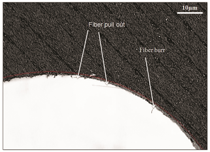
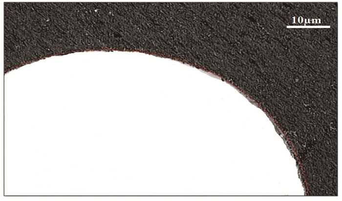
Onyx-Glass Fiber Hybrid Polymer Composite have machined through AWJM at different process parameters, as shown in Figs. 11-16 respectively. The striated marks after drilling by AWJM can be observed in Figs. 11-12. The striated marks would result in the higher delamination and surface roughness. These effects are mainly produced because of the higher traverse speed (50 mm/min) and the lower abrasive mass flow rate (250 g/min). The rougher surface is bringing with a high quantity of detrimental defects such as fiber burr, fiber pullout, fiber matrix debonding, cracking and severe delamination, which can be seen in Figs. 11, 12, 14 and 15. Whereas higher AMFR (450 g/min) and lower TS rate leads to lower surface roughness and minimum delamination, due to that no defects were presented in Figs. 13 and 16. The higher abrasive water jet pressure (380 MPa) and AMFR (450 g/min), lower TS (30 mm/min) had better surface roughness (1.34 μm) and minimum delamination factor at hole entry and exit(0.900, 0.892). In the case of lower AMFR (350 to 250 g/min) and higher TS (40 to 50 mm/min), there is a higher surface roughness and maximum delamination factor at hole entry and exit, as shown in Table 6. This is because of increasing the TS rate of the focusing nozzle, which leads to lesser amounts of abrasive particles obtainable to overlap with the drilled area; it could be the outcome of superior surface roughness and delamination. With the increase in kinetic energy of AMFR and lower TS rate, minimum delamination and surface roughness can be achieved. The drilling diameter is also one of the major influencing parameters to obtain better surface roughness and minimum delamination followed by increasing the AMFR with a lower TS rate. The drilling diameter (8 to 12 mm) has higher surface roughness and delamination which was observed by decreasing the AMFR (450 to 250 g/min) and increasing the TS rate (30 to 50 mm/min) in the present study. Finally with increase in kinetic energy of AMRF along with lower TS rate, it can be arrived that better surface roughness are achieved for onyx-glass composite.

|
Fig.11 Delamination at entry drilled hole surface of drilling diameter (8 mm), TS rate (50 mm/min), and AMFR (450 g/min) |
|
Fig.12 Delamination at entry drilled hole surface of drilling diameter (10 mm), TS rate (50 mm/min), and AMFR (250 g/min) |
|
Fig.13 Delamination at entry drilled hole surface at drilling diameter (12 mm), TS rate (30 mm/min), and AMFR (450 g/min) |

|
Fig.14 Delamination at exit drilled hole surface at drilling diameter (10 mm), TS rate (50 mm/min), and AMFR (250 g/min) |

|
Fig.15 Delamination at exit drilled hole surface at drilling diameter (12 mm), TS rate (50 mm/min), and AMFR (350 g/min) |

|
Fig.16 Delamination at exit drilled hole surface at drilling diameter (12 mm), TS rate (30 mm/min), and AMFR (450 g/min) |
2.5 Comparative Studies of Different Machining Techniques Process Parameters
Table 12 indicates the delamination factor and surface roughness values of various types of fiber reinforced polymer (FRP) composites while machining through conventional and unconventional processes. Compared with various machining methods such as laser machining (LM), water jet machining, Electrical Discharge Machining (EDM) and Conventional Vertical drilling machine (CVDM), the AWJM shows minimum delamination and surface roughness values, which were noted in the present study.
| Table 12 Comparative studies of delamination and surface roughness values obtained by distinct machining techniques |
Moreover, the AWJM process is best suitable method for the machining of metals, nonmetals, ceramics, natural fiber composites and FRP composites which have been used in manufacturing industries. Because the AWJM process does not generate heat at the cutting zone with minimal cutting force over the other machining methods[51]. The controlled AWJM process parameters such as higher AMFR, lower TS rate and superior water jet pressure lead to better surface roughness and reduced delamination of OGFHPC than other process parameters. The AWJM is low cost production technique, time-saving process during mass production and also environmentally eco-friendly.
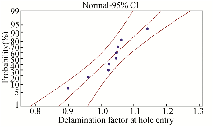
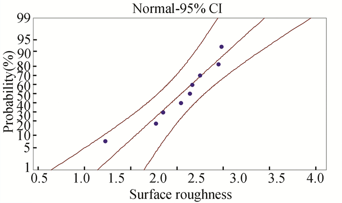
2.6 Probability Plot Utility Responses of AWJMFigs. 17-19 show the probability plot of delamination factor at the entry of hole, exit of the hole and its corresponding surface roughness respectively. From the probability plot, it was observed that the response values of the delamination factor at hole entry and exit, and the surface roughness points have been fitted within the central line as defined by the central limit theorem. And also, the response values of the data are shown the goodness of fit. Hence, the probability plot was accomplished that the response data are characteristically distributed as closer to within the central line, as shown in Figs. 17-19.
|
Fig.17 Probability plot of delamination factor at hole entry |

|
Fig.18 Probability plot of delamination factor at hole exit |
|
Fig.19 Probability plot of surface roughness |
2.7 Pseudocode of Algorithms for Validation of Results
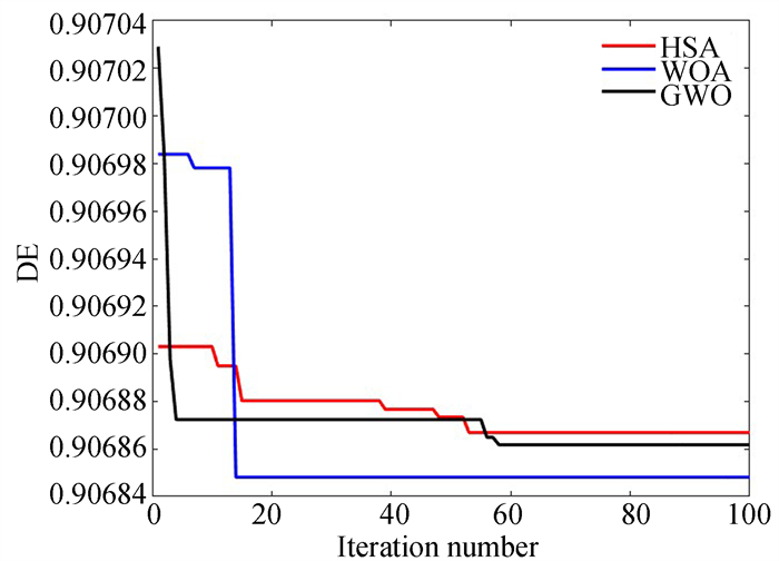
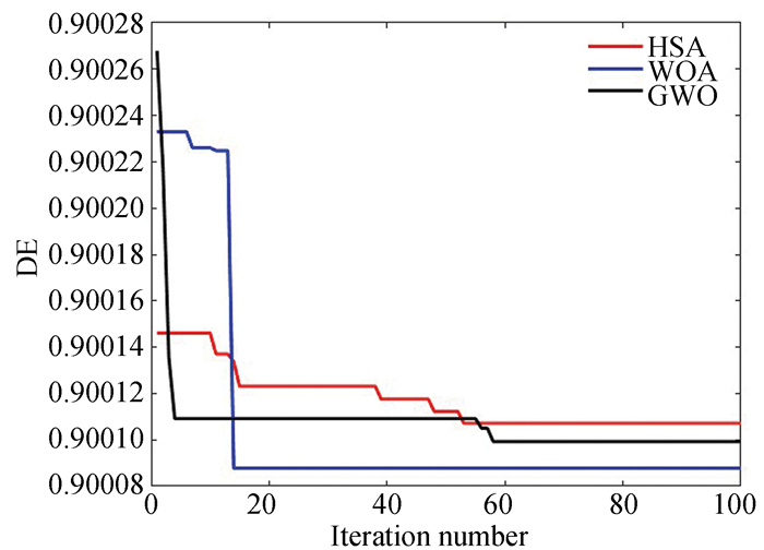
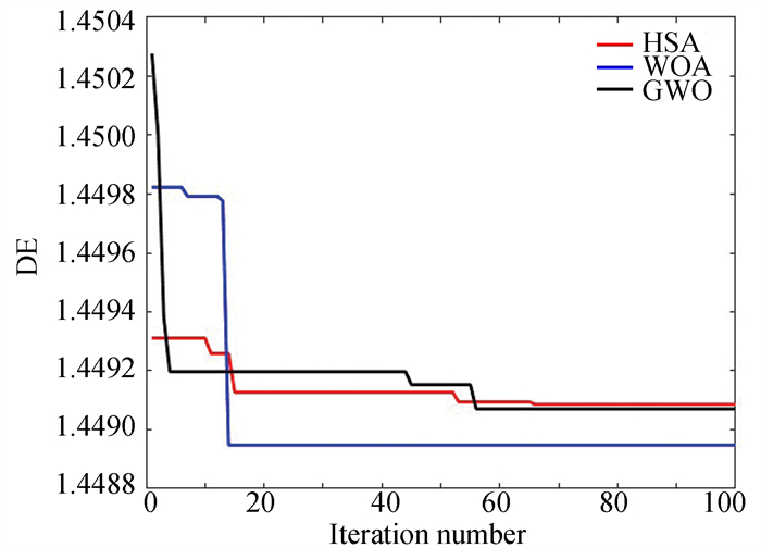
Based on the optimization algorithms such as Harmony Search Algorithm (HSA), WOA and GWOA, the optimum AWJM drilling process parameters were found and validated, as shown in Figs 20-22, and tabulated in Table 13.
|
Fig.20 Convergence plot for Fd at entry |
|
Fig.21 Convergence plot for Fd at exit |
|
Fig.22 Convergence plot for SR |
| Table 13 Confirmation test for AWJM process parameters responses |
2.7.1 Harmony search algorithm
Initialize the population of harmony i.e. parameters (DD, TS and AF)/
While (it ≤ max_it) do
For every i=1∶nh do
Determine the robustness functions (DE, DX and SR)
End For
Calculate relative closeness value using TOPSIS method (fi)
Sort fi in descending order and store the first harmony's data as Xit. and Fit.
For every agreement i=1 to nh
Enhance the Harmony
Based on rhmcr from the recall
Based on rpar with pitch modification
Novel harmony within the limits
End For
End While
Using TOPSIS (Technique for Order Preference by Similarity to Ideal Solution) method change Fit. into fi.
Type fi in descending order and show the first harmony's data which is optimal data.
2.7.2 Whale optimization algorithmRandomly begin the population of whales and its positions (DD, TS and AF)
Evaluate the fitness values of whales (DE, DX and SR)
Calculate Relative closeness value using TOPSIS method (fi)
Arrange fi in decreasing order and collect the initial whale's information as Xit. and Fit.
Set the first whale's data as best explore agent X*
While (it ≤ max_it)
Determine the significance of agent
For every investigate agent
if h < 0.5 then
If mod (A) < 1 then X·(it+1) = X· (it) - A.D
further if mod (A)≥1 then X·(it+1) =Xr and (it)-A.D*
end if
further if h≥0.5 then
X·(it+1) = D'. e.bl cos (2πl) + X·(it)
end if
end for
Calculate the robustness of X·(it+1) and update X*
End while
Through TOPSIS technique converts Fit. into fi
Sort fi in decreasing order and exhibit the first whale's numbers which is optimal data
2.7.3 Pseudocode for GWO algorithmInitialize no. of grey wolf's position (Xij - i = 1, 2, …, nw and j=1, 2, …, nd i.e. DD, TS and AF)
While (it ≤ max_it)
Find out the robustness utility Fik (k=1, 2, …, nf i.e. DE, DX and SR) of each wolf
Calculate Relative closeness value using TOPSIS method (fi)
Sort fi in decreasing order and set as sfi and store the first wolf's data as Xit. and Fit.
Through the sorted data, allocate Xa. = X1, Xb. = X2. and Xd. = X3.
Compute a=2-it·(2/nitr)
For every wolf
Modernize the location through
A1=2ar and ()-a and C1 = 2r and () and Da.=abs(C1Xa.-Xi.) and X1. = Xa.-A1Da.
A2=2ar and ()-a and C2 = 2r and () and Db.=abs(C1Xb.-Xi.) and X2. = Xb.-A2Db.
A3=2ar and ()-a and C3 = 2r and () and Dd.=abs(C1Xd.-Xi.) and X3. = Xd.-A3Dd.
Xi. = (X1. + X2. + X3.)/3
Confirm Xi. within bounds
End
End
Through TOPSIS technique converts Fit. into fi
Sort fi in decreasing order and exhibit the first wolf's data which is optimal data
2.7.4 Pseudocode for TOPSIS techniqueInterpret objectives matrix - Ork with weights (Wk) and sort of objective (OS)
For every variable r=na
For every acknowledgement k=nr
Find Normalized significance of Ork (Nrk)
Estimate execution Matrix (Ark)
End
End
For every feedback k=nr
Establish optimistic ideal (Pk) and negative ideal result (Mk)
End
For every variable r=na
Find the ideal (SPr) and negative ideal (SMr) severance values
Calculate comparative nearness (Rr)
End
Organize variable in descending sort station on Rr
Show the alternating which has largest Rr value
2.8 Confirmation Test of AWJ Drilling Process Parameters on OGFHPCThe confirmation was carried out using optimized AWJ drilling process parameters such as AMFR (450 g/min), TS (30mm/min), and DD (12 mm), to acquire the delamination factor(Fd) at hole entry, exit and surface roughness, as shown in Table 13. From the experimental and the calculated results of the regression model equation, validated through HSA, WOA and GWO, both results were obtained at marginal least error of less than 9%. It was found that the experimental and forecasted results are both good improvements obtained through Taguchi analysis and Optimization Algorithms (Figs. 20-22). It was observed that the proposed model is appropriate for the selected range of AWJ drilling process parameters of Onyx-Glass Fiber Hybrid Polymer Composite.
3 ConclusionsThe fabrication of Onyx-Glass Fiber Hybrid Polymer Composite (OGFHPC) was used as 3D printing method followed by filament type fused deposition modeling (FDM) technology of the Mark forged Mark Two 3D-composite printer. The AWJM experiments were performed based on the design of experiments (DoE) through Taguchi Technique and validated using HSA, WOA and GWO algorithms. The following conclusions were drawn based on the outcome of this research work :
1) The 3D printed samples of OGFHPC have been machined using AWJM. It was concluded that optimized AWJ process parameters give better surface roughness and minimum delamination factor than other machining methods.
2) The surface roughness and delamination factor decrease, as the higher abrasive water jet pressure, increase of AMFR, with the lower TS rate. This is because higher AWJP and AMFR with lower TS lead to increase the momentum of kinetic energy of the abrasive particles. At lower TS rate, the number of abrasive particles increases, which has an impact on the work piece per unit time and hence, better surface roughness and minimization of delamination factor.
3) The higher AMFR of 450 g/min, lower TS of 30 mm/min and maximum DD of 12 mm produced the minimum delamination factor with a hole entry of 0.900, an exit of 0.892 and the surface roughness of 1.34 μm. It was the optimum drilling process parameters of AWJM for the 3D printed samples of OGFHPC. References
| [1] |
Ramalingam P S, Mayandi K, Balasubramanian V, et al. Effect of 3D printing process parameters on the impact strength of onyx-Glass fiber reinforced composites. Materials Today: Proceedings, 2021, 45: 6154-6159. DOI:10.1016/j.matpr.2020.10.467 (  0) 0) |
| [2] |
Parmiggiani A, Prato M, Pizzorni M. Effect of the fiber orientation on the tensile and flexural behavior of continuous carbon fiber composites made via fused filament fabrication. The International Journal of Advanced Manufacturing Technology, 2021, 114(7): 2085-2101. (  0) 0) |
| [3] |
Ghebretinsae F, Mikkelsen O, Akessa A. Strength analysis of 3D printed carbon fibre reinforced thermoplastic using experimental and numerical methods. IOP Conference Series: Materials Science and Engineering. Bristol: IOP Publishing Ltd., 2019: 012024. DOI:10.1088/1757-899X/700/1/012024
(  0) 0) |
| [4] |
Piramanayagam S R, Kalimuthu M, Nagarajann R, et al. Experimental investigation and statistical analysis of additively manufactured onyx-carbon fiber reinforced composites. Journal of Applied Polymer Science, 2021, 138(18): 50338. DOI:10.1002/app.50338 (  0) 0) |
| [5] |
Fang F, Gu C, Hao R, et al. Recent progress in surface integrity research and development. Engineering, 2018, 4(6): 754-758. DOI:10.1016/j.eng.2018.11.005 (  0) 0) |
| [6] |
Cantwell W J, Morton J. The impact resistance of composite materials—a review. Composites, 1991, 22(5): 347-362. DOI:10.1016/0010-4361(91)90549-V (  0) 0) |
| [7] |
Cantwell W, Morton J. Detection of impact damage in CFRP laminates. Composite Structures, 1985, 3(3-4): 241-257. DOI:10.1016/0263-8223(85)90056-X (  0) 0) |
| [8] |
Vedula M, Koczak M J. Impact resistance of cross-plied polyphenylene sulfide composites. Journal of Thermoplastic Composite Materials, 1989, 2(3): 154-163. DOI:10.1177/089270578900200301 (  0) 0) |
| [9] |
Abrao A, Rubio J C, Faria P, et al. The effect of cutting tool geometry on thrust force and delamination when drilling glass fibre reinforced plastic composite. Materials & Design, 2008, 29(2): 508-513. DOI:10.1016/j.matdes.2007.01.016 (  0) 0) |
| [10] |
Benardos P, Vosniakos G-C. Predicting surface roughness in machining: a review. International Journal of Machine Tools and Manufacture, 2003, 43(8): 833-844. DOI:10.1016/S0890-6955(03)00059-2 (  0) 0) |
| [11] |
Rubio J C C, da Silva L J, de Oliveira Leite W, et al. Investigations on the drilling process of unreinforced and reinforced polyamides using Taguchi method. Composites Part B: Engineering, 2013, 55: 338-344. DOI:10.1016/j.compositesb.2013.06.042 (  0) 0) |
| [12] |
Tan C L, Azmi A I, Muhammad N. Performance evaluations of carbon/glass hybrid polymer composites. Advanced Materials Research, 2014, 980: 8-12. DOI:10.4028/www.scientific.net/AMR.980.8 (  0) 0) |
| [13] |
Heidary H, Karimi N Z, Minak G. Investigation on delamination and flexural properties in drilling of carbon nanotube/polymer composites. Composite Structures, 2018, 201: 112-120. DOI:10.1016/j.compstruct.2018.06.041 (  0) 0) |
| [14] |
Unde P, Gayakwad M, Ghadge R. Abrasive water jet machining of composite materials-a review. Int J Innov Res Sci Eng Technol, 2014, 3: 6-8. (  0) 0) |
| [15] |
Shaikh A, Jain P. Experimental study of various technologies for cutting polymer matrix composites. Int J Adv Eng Technol, 2012, 2(1): 81-88. (  0) 0) |
| [16] |
Ramulu M, Arola D. Water jet and abrasive water jet cutting of unidirectional graphite/epoxy composite. Composites, 1993, 24(4): 299-308. DOI:10.1016/0010-4361(93)90040-F (  0) 0) |
| [17] |
Jani S, Kumar A S, Khan M A, et al. Machinablity of hybrid natural fiber composite with and without filler as reinforcement. Materials and Manufacturing Processes, 2016, 31(10): 1393-1399. DOI:10.1080/10426914.2015.1117633 (  0) 0) |
| [18] |
Dubey M, Kumar V, Kaur M, et al. A systematic review on harmony search algorithm: theory, literature, and applications. Mathematical Problems in Engineering, 2021, 2021: Article ID 5594267. DOI: 10.1155/2021/5594267.
(  0) 0) |
| [19] |
Ramesha N, Akhtar S. Abrasive water jet machining and mechanical behavior of banyan tree saw dust powder loaded polypropylene green composites. Polymer Composites, 2016, 37(6): 1754-1764. DOI:10.1002/pc.23348 (  0) 0) |
| [20] |
Prabu V A, Kumaran S T, Uthayakumar M. Performance evaluation of abrasive water jet machining on banana fiber reinforced polyester composite. Journal of Natural Fibers, 2017, 14(3): 450-457. DOI:10.1080/15440478.2016.1212768 (  0) 0) |
| [21] |
Saini M. Optimization the process parameter of FDM 3D printer using Taguchi method for improving the tensile strength. International Journal of All Research Education and Scientific Methods, 2019, 7(4): 16-25. (  0) 0) |
| [22] |
Ali M H, Issayev G, Shehab E, et al. A critical review of 3D printing and digital manufacturing in construction engineering. Rapid Prototyping Journal, 2022, 28(7): 1312-1314. DOI:10.1108/RPJ-07-2021-0160 (  0) 0) |
| [23] |
Dharmalingam G, Prasad M A, Salunkhe S. Investigation of impact strength at different infill rates biodegradable PLA constituent through fused deposition modeling. Materials Today: Proceedings, 2022, 62: 551-558. DOI:10.1016/j.matpr.2022.03.591 (  0) 0) |
| [24] |
Muvunzi R, Mpofu K, Daniyan I. An evaluation model for selecting Part Candidates for additive manufacturing in the transport sector. Metals, 2021, 11(5): 765. DOI:10.3390/met11050765 (  0) 0) |
| [25] |
Khorasani M, Ghasemi A, Rolfe B, et al. Additive manufacturing a powerful tool for the aerospace industry. Rapid Prototyping Journal, 2021, 28(1): 87-100. DOI:10.1108/RPJ-01-2021-0009 (  0) 0) |
| [26] |
Kumar V, Das P P, Chakraborty S. Grey-fuzzy method-based parametric analysis of abrasive water jet machining on GFRP composites. Sādhanā, 2020, 45(1): 1-18. DOI:10.1007/s12046-019-1235-5 (  0) 0) |
| [27] |
Abdulhameed O, Al-Ahmari A, Ameen W, et al. Additive manufacturing: Challenges, trends, and applications. Advances in Mechanical Engineering, 2019, 11(2): 1687814018822880. DOI:10.1177/1687814018822880 (  0) 0) |
| [28] |
Pal A K, Mohanty A K, Misra M. Additive manufacturing technology of polymeric materials for customized products: recent developments and future prospective. RSC Advances, 2021, 11(58): 36398-36438. DOI:10.1039/D1RA04060J (  0) 0) |
| [29] |
Atzeni E, Iuliano L, Minetola P, et al. Redesign and cost estimation of rapid manufactured plastic parts. Rapid Prototyping Journal, 2010, 16(5): 308-317. DOI:10.1108/13552541011065704 (  0) 0) |
| [30] |
Benedict G. Nontraditional Machining Processes. New York & Basel: Marcel Dekker Inc, 1987: 231-232.
(  0) 0) |
| [31] |
Vigneshwaran S, John K, Deepak Joel Johnson R, et al. Conventional and unconventional machining performance of natural fibre-reinforced polymer composites: A review. Journal of Reinforced Plastics and Composites, 2021, 40(15-16): 553-567. DOI:10.1177/0731684420958103 (  0) 0) |
| [32] |
Arunkumar K, Murugarajan A. Influence of graphene filler on surface quality of hybrid composite during AWJM. Materials and Manufacturing Processes, 2021, 36(11): 1248-1255. DOI:10.1080/10426914.2021.1905836 (  0) 0) |
| [33] |
Dharmalingam G, Mariappan R, Murali A P. Effect of sintering parameters on mechanical properties of 17-Cr ferritic ODS steel through taguchi approach. Journal of The Institution of Engineers (India): Series D, 2019, 100(2): 163-176. DOI:10.1007/s40033-019-00183-4 (  0) 0) |
| [34] |
Lenin N, Siva Kumar M. Harmony search algorithm for simultaneous minimization of bi-objectives in multi-row parallel machine layout problem. Evolutionary Intelligence, 2021, 14(4): 1495-1522. DOI:10.1007/s12065-020-00419-3 (  0) 0) |
| [35] |
Zhang J, Zhang P. A study on harmony search algorithm and applications. Proceedings of the 2018 Chinese Control And Decision Conference (CCDC). Piscataway: IEEE, 2018, 736-739. (  0) 0) |
| [36] |
Ning G-Y, Cao D-Q. Improved whale optimization algorithm for solving constrained optimization problems. Discrete Dynamics in Nature and Society, 2021(12): 1-13. DOI:10.1155/2021/8832251 (  0) 0) |
| [37] |
Chakraborty S, Saha A K, Sharma S, et al. A hybrid whale optimization algorithm for global optimization. Journal of Ambient Intelligence and Humanized Computing, 2023, 14: 431-467. (  0) 0) |
| [38] |
Mirjalili S, Lewis A. The whale optimization algorithm. Advances in Engineering Software, 2016, 95: 51-67. DOI:10.1016/j.advengsoft.2016.01.008 (  0) 0) |
| [39] |
Gao Z-M, Zhao J. An improved grey wolf optimization algorithm with variable weights. Computational Intelligence and Neuroscience, 2019, 2019: Article ID 2981282. DOI: 10.1155/2019/2981282.
(  0) 0) |
| [40] |
Sharma I, Kumar V, Sharma S. A comprehensive survey on grey wolf optimization. Recent Advances in Computer Science and Communications (Formerly: Recent Patents on Computer Science), 2022, 15(3): 323-333. DOI:10.2174/2666255813999201007165454 (  0) 0) |
| [41] |
Mirjalili S, Mirjalili S M, Lewis A. Grey wolf optimizer. Advances in Engineering Software, 2014, 69: 46-61. DOI:10.1016/j.advengsoft.2013.12.007 (  0) 0) |
| [42] |
Hou Y, Gao H, Wang Z, et al. Improved grey wolf optimization algorithm and application. Sensors, 2022, 22(10): 3810. DOI:10.3390/s22103810 (  0) 0) |
| [43] |
Shen C, Zhang K. Two-stage improved Grey wolf optimization algorithm for feature selection on high-dimensional classification. Complex & Intelligent Systems, 2022, 8: 2769-2789. (  0) 0) |
| [44] |
Dharmalingam G, Mariappan R, Prasad M A. Optimization of wear process parameters on 16-Cr Ferritic ODS steel through Taguchi approach. Materials Today: Proceedings, 2020, 23: 583-589. DOI:10.1016/j.matpr.2019.05.413 (  0) 0) |
| [45] |
Ming Ming I W, Azmi A I, Chuan L C, et al. Experimental study and empirical analyses of abrasive waterjet machining for hybrid carbon/glass fiber-reinforced composites for improved surface quality. The International Journal of Advanced Manufacturing Technology, 2018, 95(9): 3809-3822. (  0) 0) |
| [46] |
Irina M M W, Azmi A I, Lee C C. Machinability study of hybrid FRP composite using abrasive waterjet trimming technology. Key Engineering Materials, 2017, 118-124. DOI:10.4028/www.scientific.net/KEM.740.118 (  0) 0) |
| [47] |
Dhakal H N, Ismail S O, Ojo S O, et al. Abrasive water jet drilling of advanced sustainable bio-fibre-reinforced polymer/hybrid composites: a comprehensive analysis of machining-induced damage responses. The International Journal of Advanced Manufacturing Technology, 2018, 99(9): 2833-2847. (  0) 0) |
| [48] |
Hejjaji A, Singh D, Kubher S, et al. Machining damage in FRPs: Laser versus conventional drilling. Composites Part A: Applied Science and Manufacturing, 2016, 82: 42-52. DOI:10.1016/j.compositesa.2015.11.036 (  0) 0) |
| [49] |
Guu Y H, Hocheng H, Tai N H, et al. Effect of electrical discharge machining on the characteristics of carbon fiber reinforced carbon composites. Journal of Materials Science, 2001, 36(8): 2037-2043. DOI:10.1023/A:1017539100832 (  0) 0) |
| [50] |
Feito N, Díaz-Álvarez J, Díaz-Álvarez A, et al. Experimental analysis of the influence of drill point angle and wear on the drilling of woven CFRPs. Materials, 2014, 7(6): 4258-4271. DOI:10.1016/j.compstruct.2018.11.018 (  0) 0) |
| [51] |
Natarajan Y, Murugesan P K, Mohan M, et al. Abrasive water jet machining process: A state of art of review. Journal of Manufacturing Processes, 2020, 49: 271-322. DOI:10.1016/j.jmapro.2019.11.030 (  0) 0) |
 2023, Vol. 30


