Since the end of the 20th century, ultrasonic imaging technology has played a crucial role in medical diagnosis, non-destructive testing, and underwater detection[1]. The design of ultrasonic transducers and their array layout are crucial in ultrasonic imaging systems because they determine the quality of imaging. Conventional ultrasonic transducers use piezoelectric blocks with relatively low accuracy and high cost. Recently, piezoelectric micro-mechanical ultrasonic transducers (PMUTs) have been developed with better lateral sensitivity owing to the smaller single-block size and batch fabrication of arrays; however, PMUTs have some disadvantages, such as limited center frequencies and unmatched human acoustic impedance[2]. In contrast, capacitive micromechanical ultrasonic transducers (CMUTs) based on MEMS technology have the advantages of a wider bandwidth, better electrical and thermal stability, lower manufacturing cost, and better compatibility with integrated circuits[3-5]. Therefore, CMUT is considered a better replacement for PMUT and conventional piezoelectric block-based transducers.
As an ultrasonic imaging device, CMUT has received extensive attention, and it can be used as another type of sensing element. Zheng et al.[6] used CMUT as a high-performance humidity sensor by fabricating composite films based on the hydrophilicity of biodegradable and renewable cellulose nanocrystals (CNCs), and a sensitivity of up to 2 kHz/%RH was achieved, together with fast response, recovery, and repeatability. Hernandez et al.[7] designed a binary gas-mixture discrimination sensor using the resonant characteristics of the CMUT to identify and determine the gas concentration by continuously measuring the attenuation spectrum. Therefore, CMUTs have potential and advantages as multifunctional or versatile sensors. It is crucial that CMUTs be further explored for other potential applications.
Pressure sensing plays a crucial role in industrial production, aerospace, biomedicine, and other fields[8-9]. However, some industries have high requirements on sensitivity of pressure sensing but strict limits on sensors, such as flexibility and/or biocompatibility, and a small range of pressure changes to produce a very sensitive response, which are very challenging because most pressure sensors are bulky and inflexible, together with limited detection range and low sensitivity[10].
Pressure sensors have always been of interest to researchers. Recently, many studies have been conducted on resonant and capacitive pressure sensors. For instance, Xu et al.[11] used a side beam to suppress the z-direction displacement of a resonant sensor to improve its stability and a double-sided comb tooth structure to improve its sensitivity, reaching a sensitivity of 30 Hz/kPa. Zhang et al.[12] used a pressure conversion composite structure and a quartz DETF resonator to form a differential output structure with good linearity, which could be used for pressure detection in the MPa range, but not ideal sensitivity. Lin et al.[13] developed a capacitive pressure sensor with a double-layer dielectric structure with a sensitivity of 0.6 kPa-1. Zhao et al.[14] developed a capacitive pressure sensor with a bionic structure using a lotus leaf surface, with a maximum sensitivity of 1.207 kPa-1, but the response time was not sufficiently fast. The flexible capacitive pressure sensor developed by Wang et al.[15] with a BaTiO3/MwCNTs/PDMS compliant structure as a dielectric layer had a sensitivity of 1.24 kPa-1.
Based on its structure and working mechanism, CMUT can be used as a micromechanical resonant pressure sensor[16]. It has superior resonance characteristics, making it promising for pressure sensing. Moreover, the structure of CMUT can be regarded as a parallel plate capacitor with a movable upper plate[17]. Therefore, it can be used as both a resonant pressure sensor and a capacitive pressure sensor. However, its potential for pressure-sensing and the associated sensitivity are still unclear. This study was conducted based on a multiphysics simulation to explore the potential of the CMUT as a pressure sensor.
1 Principle 1.1 Typical Structure of the CMUTFig. 1 shows a basic model of a conventional CMUT cell with seven parts: the top electrode, flexible membrane, cavity, post, electrical insulation layer, bottom electrode, and main structure substrate[18]. Among them, the insulation layer plays a protective role in ensuring electrical insulation between the top and bottom electrodes, preventing the two electrodes from accidentally being engaged during operation, which could result in a short circuit[19].

|
Fig.1 Schematic structure of a typical CMUT cell |
1.2 Working as a Resonant Pressure Sensor
When both AC and DC bias voltages were applied between the top and bottom electrodes, the membrane vibrated upward and downward together with the top electrode. Resonance occurs when the applied AC voltage frequency is equal or close to the resonant frequency of the CMUT device.
The resonance frequency of the CMUT shifts when the top electrode is subjected to a different bias voltage or an external pressure. Therefore, the frequency shift can be used to calculate the value of the external pressure, and the sensitivity can be derived accordingly.
Because the thickness of the CMUT's vibration membrane is significantly small compared with its surface area, its vibration characteristics can be analyzed using the thin plate theory[20]. The CMUT membrane can be considered a circular thin plate with a fixed edge, and its natural frequency in air or vacuum can be expressed as follows[21]:
| fn=μ2nh4πr2m√E3ρ(1−v2) | (1) |
The fundamental frequency, which is also known as the resonance frequency of the CMUT, can be obtained according to Ref. [21] as follows:
| f0=0.47hr2m√Eρ(1−v2) | (2) |
where f0 is the resonance frequency of the CMUT, μn is the root of the cylindrical Bezier function, n is a natural number, h is the thickness of the CMUT membrane, rm is the radius of the membrane, E is the young modulus, ρ is the material's density and v is the Poisson's ratio.
Therefore, when pressure is applied, the pressure-detection sensitivity is given according to the following formula:
| S=1f0⋅f−f0P | (3) |
where S is the sensitivity, f0 is the resonance frequency of the CMUT when pressure and voltage are not applied, and f is the resonant frequency of the CMUT when pressure P is applied.
1.3 Working as Capacitive Pressure SensorThe top and bottom electrodes of the CMUT can be used as a parallel plate capacitor. As the top plate has fixed edges, the deformation of the top plate caused by pressure is not uniform. Its maximum deformation is denoted by ω, and x0 is the initial location, as shown in Fig. 2.

|
Fig.2 Cross section of the CMUT deformation |
According to Timosinko's Plate and Shell Theory[22], assuming that the entire plate surface is subjected to pressure of strength P, the shear force at distance "r" from the plate center is Q, there is Eqs. (4) and (5):
| 2πr⋅Q=πr2⋅P | (4) |
| Q=Pr2 | (5) |
Then, according to the deflection formula, Eq. (6) can be obtained:
| ddr[1r⋅ddr(rdw dr)]=QD=Pr2D | (6) |
| D=Eh312(1−ν2) | (7) |
where D represents the stiffness of the top plate.
Because the circular CMUT vibration film is fixed with supports around it, the derivative of the displacement function on its boundary is zero, thus the following boundary conditions are obtained:
| dw dr|r=0=0,dw dr|r=rm=0 |
By applying a series of integral derivations to Eq. (6) and substituting the boundary conditions, the following results can be obtained:
| w(r)=Pr4m64D(1−r2r2m)2 | (8) |
As the plate is round and the edge is fixed, the capacitance after deformation can be calculated through integration[23-25]. When the membrane deformation is less than the film thickness, the capacitance C' after deformation is
| C′=∬ | (9) |
where x represents the actual location of the membrane, ε is the relative dielectric constant of membrane.
Integrating the above equation using Eq. (9), there is
| C^{\prime}=8 {\rm{ \mathsf{ π} }} \varepsilon \sqrt{\frac{D}{P x_0}} \tanh ^{-1}\left(\frac{r_{\mathrm{m}}^2}{8} \sqrt{\frac{P}{D x_0}}\right) | (10) |
The sensitivity of the capacitance to detect pressure changes can be expressed as[26]
| S^{\prime}=\frac{1}{C_0} \cdot \frac{C_0-C^{\prime}}{P} |
where C0 is the initial capacitance.
1.4 Collapse VoltageThe collapse voltage of the CMUT refers to the threshold for the DC bias voltage applied between the top and bottom electrodes, above which the membrane collapses instantly and directly onto the insulating layer[27]. At this point, the working state of the transducer changes significantly and the transducer loses its normal operation. The studies in this paper were conducted under the condition that the collapse voltage is not exceeded.
When studying the static characteristics of the CMUT cell, the cell can be considered as a flat capacitor with a fixed lower electrode and movable upper electrode. A simplified view of the model is shown in Fig. 3, which assumes the top layer is mass represented by m.

|
Fig.3 Equivalent model diagram of the CMUT |
When a bias voltage is applied between the upper and lower electrodes, the CMUT is subjected to both electrostatic and elastic restoring forces. The membrane is in equilibrium when the elastic restoring force on the membrane is equal to the electrostatic force.
The static force Fe and elastic restoring force Fs are calculated as follows:
| x=x_0-w | (11) |
| (12) |
| F_e=-\frac{\mathrm{d}}{\mathrm{d} x}\left(\frac{1}{2} C V_{\mathrm{D}}{ }^2\right)=\frac{\varepsilon_0 A V_{\mathrm{D}}{ }^2}{2\left(x_0-w\right)^2}=\frac{\varepsilon_0 A V_{\mathrm{D}}{ }^2}{2 x^2} | (13) |
| F_s=-k w=-k\left(x_0-x\right) | (14) |
where C represents the capacitance value after deformation, ε0 is the relative dielectric constant of the vacuum medium, A is the area of the top electrode, VD is the DC bias applied between the two electrodes, and kis the equivalent elastic coefficient.
When the electrostatic force is equal to the elastic restoring force, Eq. (15) can be obtained, from which the critical distance between the top and bottom electrodes and the critical voltage at equilibrium can be derived.
| \frac{\varepsilon_0 A V_{\mathrm{D}}^2}{2 x^2}=k\left(x_0-x\right) | (15) |
| V_{\mathrm{D}}=\sqrt{\frac{2 k x^2}{\varepsilon_0 A}\left(x_0-x\right)} | (16) |
Taking the derivative of Eq. (16) for the first order and setting it to 0, there is
| \frac{\mathrm{d} V_{\mathrm{d}}}{\mathrm{d} x}=\sqrt{\frac{2 k}{\varepsilon_0 A}} \frac{\left(2 x_0-3 x\right)}{\sqrt{x_0-x}}=0 | (17) |
Therefore, the critical position of the membrane is x=2x0/3 at equilibrium, which means that the maximal displacement of the membrane is w=x0/3.
The critical voltage obtained is also called the collapse voltage:
| V_c=\sqrt{\frac{8 k x_0^2}{27 \varepsilon_0 A}} | (18) |
The approximate expression of the elastic coefficient of the vibrating membrane is expressed as follows[26-27]:
| k=\frac{16 {\rm{ \mathsf{ π} }} h^3 E^2}{r_{\mathrm{m}}^2\left(1-v^2\right)} | (19) |
A three-dimensional simulation model of the CMUT is designed using the software COMSOL Multiphysics 5.6 version, and finite-element simulations was conducted to study the performance of the model in detecting pressure changes in this study. The simulation model was constructed according to the structure shown in Fig. 1. However, to reduce the calculation time, the actual model removes the substrate and insulation. Because the volume of the substrate was the largest, removing the substrate can reduce the calculation time significantly. The simulation was performed under the collapse voltage threshold. Thus, the insulation layer was also removed.
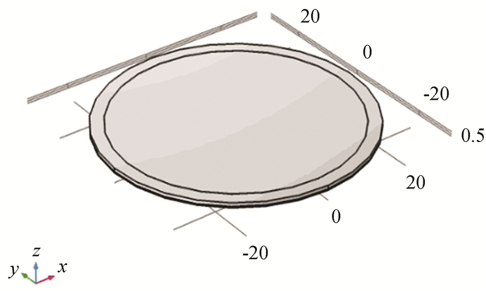
The three-dimensional imitation model is shown in Fig. 4. A diagram of the model divided into a two-dimensional axisymmetric form is shown in Fig. 5. The structural parameters of each part associated with the model are listed in Table 1.
|
Fig.4 Three-dimensional imitation model(Unit: μm) |

|
Fig.5 Diagram of the two-dimensional equivalent model |
| Table 1 Parameters for the simulations |
In the simulation, aluminum was used as the top and bottom electrodes of the CMUT model, Si material as the membrane (0.8 μm in thickness), the cavity is assumed to be the vacuum, and SiO2 material as the support arm. All materials and their related properties are listed in Table 2.
| Table 2 Material parameters for the CMUT simulation |
The module involved in the simulation was an electromechanical multiphysical field-coupling module composed of electrostatic and solid mechanics.
First, the collapse voltage of the model was calculated in the steady-state study. Subsequently, the resonant frequency was determined. An external load was then applied to the top electrode under different DC bias voltages. Thereafter, the sensitivity of pressure detection under different bias voltages was determined, and the influences of different membrane thicknesses and electrode radii were analyzed. Finally, the pressure-induced frequency and capacitance variations of the CMUT device were calculated, as well as the sensitivity and variation were derived.
3 Results and Discussion 3.1 Collapse VoltageBecause the collapse voltage determines the operating range of the device and it has a significant effect on sensitivity[17], the collapse voltage was calculated first. In this study, the membrane voltage at the critical displacement was obtained by setting the membrane to generate different deflection displacements which is shown as Zset, and the largest voltage was designated as the collapse voltage. The collapse voltage calculated using this model is shown in Fig. 6, with a typical value of approximately 46.32 V.

|
Fig.6 Collapse voltage of CMUT |
3.2 Resonant Frequency
According to Fig. 1, the sixth-order vibration modes of CMUT were calculated. Their frequencies were 4.7×10⁶, 9.7×10⁶, 9.7×10⁶, 1.6×10⁷, 1.6×10⁷, 1.8×10⁷ Hz, respectively. Particularly, the characteristic frequency of the first mode is the resonance frequency (Fig. 7), which is significantly different from the other characteristic frequencies. Therefore, the membrane is not easily interfered by other frequency modes when it resonates. This excellent resonance characteristic makes the CMUT suitable for the use as a resonance sensor.

|
Fig.7 Frequency of the first vibration mode(Unit: μm) |
3.3 Pressure Detect by Frequency
A DC bias voltage of 41.5 V was applied between the two electrodes of the CMUT, which is approximately 90% of the collapse voltage. The variation in resonance frequency with pressure under large loads (1 kPa-10 kPa) and small loads (1 Pa-100 Pa) were calculated, and the results are presented in Fig. 8. It is evident from the results that the resonance frequency of the CMUT decreased linearly with increasing pressure, and the sensitivity for pressure detection is approximately 18.95 Hz/Pa under the larger pressure range and approximately 15.5 Hz/Pa under the lower pressure range. This indicates that the pressure sensor fabricated by the CMUT device has a large pressure detection range and superior sensitivity.

|
Fig.8 Variation of frequency with pressure change |
However, when the load was extremely large, the linear change between the pressure and frequency was not good. This phenomenon is attributed to the spring softening effect of the CMUT model. An increase in pressure and a DC bias voltage can both cause spring softening. Therefore, the greater the pressure, the more obvious of the softening effect, which induces faster frequency decrease, and the greater sensitivity. The design parameters of the CMUT model can be adjusted to increase the collapse voltage when higher pressures need to be measured, whose purpose is reducing the softening effect of the bias voltage on the membrane spring[26].
Therefore, in this study, an intermediate load range is selected for the subsequent simulation, and the load range is 1 Pa-1 kPa.
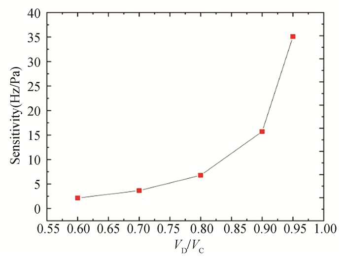
To understand the effect of different VD/VC on the pressure sensing sensitivity, DC bias voltages of 0.95, 0.90, 0.80, 0.70, and 0.60 times of the collapse voltage were used. The pressure-frequency variation results for the different bias voltages are presented in Fig. 9. The sensitivity of the pressure sensing was approximately 35.09, 15.72, 6.80, 3.66, and 2.16 Hz/Pa, which indicates that the CMUT-based pressure sensor can be used for pressure detection, and the detection sensitivity can be optimized by changing the bias voltages accordingly.
|
Fig.9 Sensitivity of different VD/VC |
As shown in Fig. 9, the closer the DC bias voltage is to the collapse voltage, the greater the sensitivity of the pressure detection. Therefore, VD/VC ratio of 95% was selected for this study.
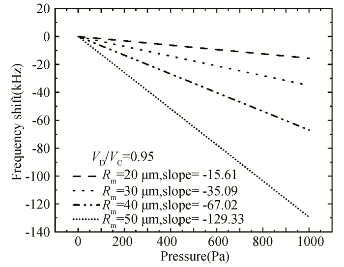
Fig. 10 shows frequency shift and the pressure sensitivity of the CMUT base pressure sensor under different membrane radii. It indicates that with the increase of the membrane radius, the detection sensitivity increases under the same bias voltage of 95% of the collapse voltage. Additionally, the sensitivity of the CMUT as a resonant pressure sensor can be 100 Hz/Pa. This performance was excellent.
|
Fig.10 Frequency shift and pressure sensitivity of different membrane radii |
In addition to changing the membrane radius, the change in the membrane thickness was studied. In the simulation, the DC bias voltage was fixed at 95% of the collapse voltage. Fig. 11 shows that the sensitivity of pressure detection decreases with an increase in the membrane thickness. In this simulation, a maximum sensitivity of 92.53 Hz/Pa was achieved by varying the film thickness. Therefore, in the practical design, thinner membrane thickness is considered to be better within a certain range of practical limitations while keeping the membrane in smaller deflection deformation (the maximum deformation of the membrane is less than 0.2 times its thickness[22]).

|
Fig.11 Frequency shift and pressure sensitivity of different membrane thickness |
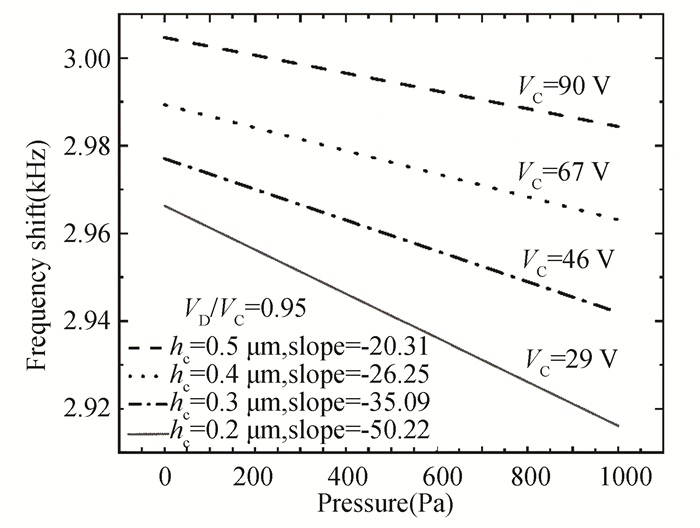
Fig. 12 shows the effect of variations in the cavity height hc on the resultant sensitivity. When hc are 0.2, 0.3, 0.4 and 0.5 μm, the sensitivities of the pressure detection are approximately -50.22, -35.09, -26.25 and -20.31 Hz/Pa, respectively. Therefore, hc is inversely proportional to sensitivity.
|
Fig.12 Frequency shift and pressure sensitivity of different cavity height |
Finally, the effect of different membrane materials on the sensor is explored, as shown in Fig. 13. Different membrane materials have different stiffnesses (Young's modulus). The higher the Young's modulus, the higher the vibration frequency of the membrane, but it is more difficult to change the frequency. As the Young's moduli of SiO2, Si, and Si3N4 gradually increase (ESiO2=70 GPa, ESi=170 GPa, ESi3N4=250 GPa), their sensitivities gradually decrease under the same pressure range.

|
Fig.13 Frequency shift and pressure sensitivity of different membrane materials |
According to the above simulation results, it is established that the CMUT has good sensitivity (up to 100 Hz/Pa) as a resonant pressure sensor, which is more than that of the silicon resonant pressure sensor of different structures currently studied[12-13]. The vibration material and the structural parameters of the CMUT, including the membrane radius, membrane thickness, and cavity height, can affect the sensitivity of the sensor. Eqs. (2) and (18) indicate that these parameters affect the resonance frequency and the collapse voltage. Fig. 12 and Fig. 13 show smaller resonant frequencies or collapse voltages result in greater sensitivity to pressure detection. Therefore, in practical design, the materials and design parameters can be chosen by designing a reasonable and lower resonance frequency and collapse voltage.
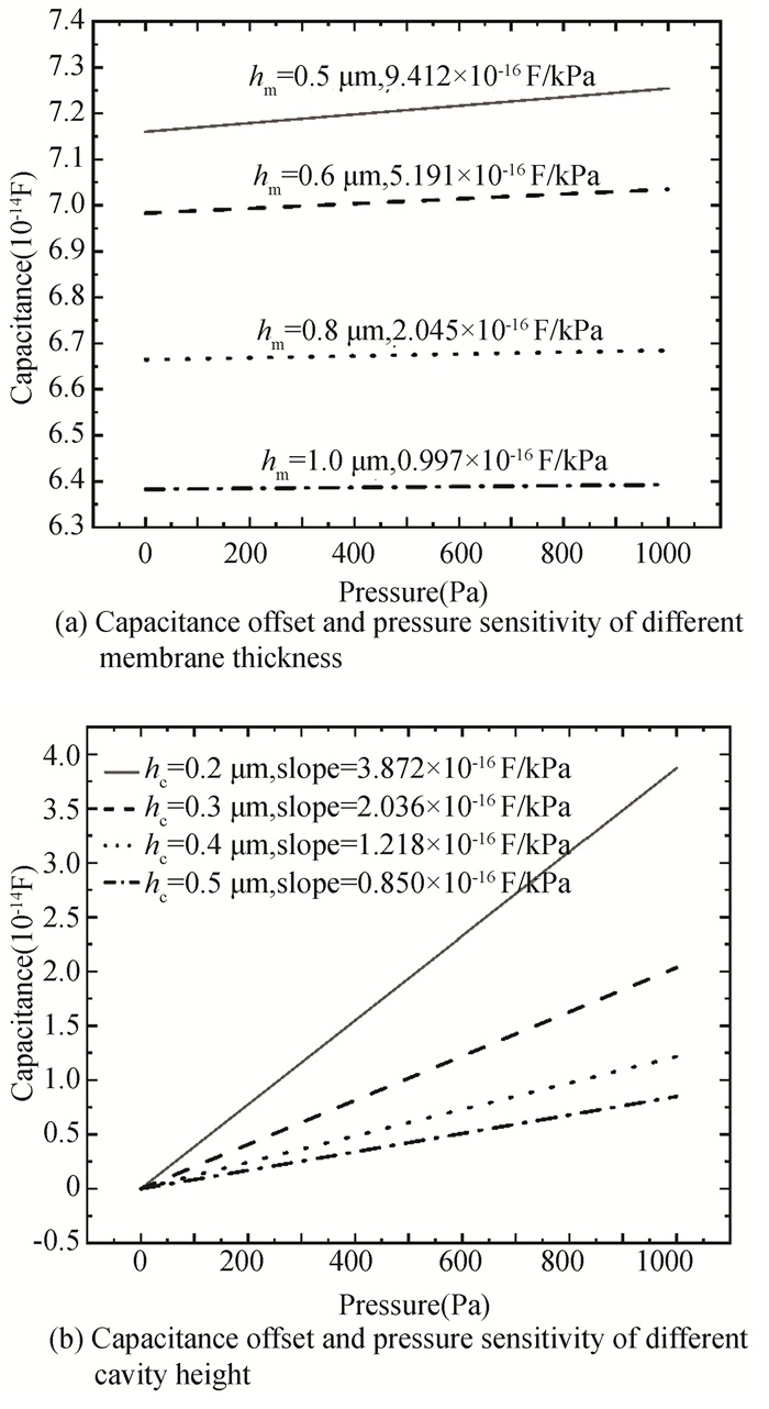
3.4 Pressure Detected by CMUT Capacitance's ChangeThe cavity structure of the CMUT enables it to be used as a capacitive pressure sensor. Figs. 14(a) and (b) show the influence of membrane thickness and cavity height on its capacitance under continuous pressure changes.
|
Fig.14 Capacitance offset and slope due to pressure changes |
The higher the pressure applied, the smaller the spacing between the top and bottom electrodes, and the greater the capacitance. Figs. 14 (a) and (b) show that the sensitivity of the CMUT as a capacitive pressure sensor increases gradually as the thickness of the membrane and cavity height decreases. Moreover, it is established that this conclusion is consistent with that of the CMUT as a resonant pressure sensor. Therefore, it is believed that the factors affecting the CMUT as a capacitive pressure sensor are similar to those affecting it as a resonance pressure sensor. However, the result of change in capacitance versus change in pressure is not significant as the change in frequency. Therefore, its sensitivity is lower, which is not of the same order of magnitude as that of frequency-based pressure detection.
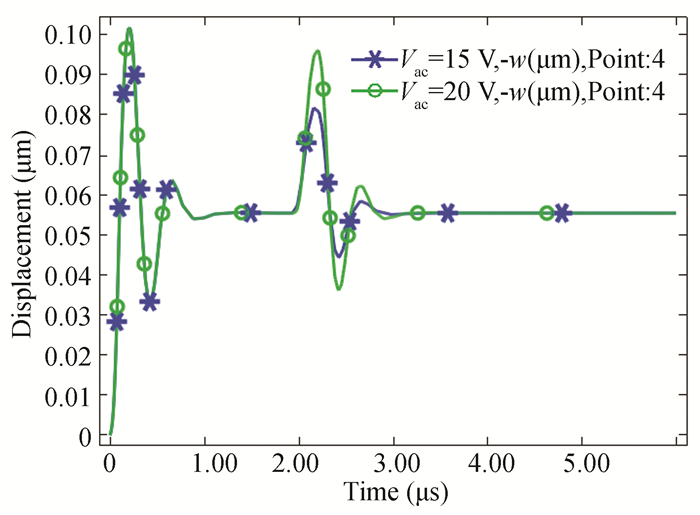
3.5 Calculation of Response TimeFig. 15 shows the response time of the CMUT as a pressure sensor. It can be observed that after applying the bias voltage VDC, the vibration reached a steady state at approximately 2 T. When t = 5 T, the membrane started to vibrate stably under the action of the sinusoidal VAC excitation signal and external load. Therefore, in general, the response time of the CMUT as a pressure sensor is very short, requiring only five cycles, and each cycle time is at the microsecond level. This response time is significantly smaller than the millisecond level in Refs.[12-16]. Therefore, the CMUT as a pressure sensor not only has a higher sensitivity, but also has a better response speed.
|
Fig.15 Respond time of CMUT as pressure sensor |
4 Conclusions
In this study, a three-dimensional CMUT model was built to determine its performance as a pressure sensor based on the pressure-induced frequency change and capacity change, as well as the influencing factors. The results indicate that the CMUT has significant advantages when used in pressure sensing, specifically for pressure detection using frequency variation, because its sensitivity is better than that of common pressure sensors, and its response time is very fast. Although the capacitance variation range is relatively small and the sensitivity of the pressure detection is relatively lower than that of the frequency-based pressure detection by the CMUT device, pressure variation can still be reasonably detected. Methods for improving the sensitivity of capacitance-based pressure detection are worth investigating in future studies.
To detect pressure changes caused by the CMUT frequency shifts, the influence of different factors on the sensing sensitivity, including the DC bias voltage, membrane thickness, cavity height, and membrane radius, were considered. The most important factor affecting sensitivity is the DC bias voltage. The closer the DC bias voltage is to the collapse voltage, the better the sensitivity of the CMUT pressure sensor. Moreover, it is established that all the parameters that affect the collapse voltage and the resonance frequency influence the sensitivity of the CMUT as a pressure sensor. Therefore, it can be concluded that the collapse voltage and resonance frequency determine the performance of the CMUT sensor.
| [1] |
Wang H L, Lv Y F, Wang C J, et al. Simulation analysis and performance testing investigation of capacitive micromachined ultrasonic transducer. International Journal of Pattern Recognition & Artificial Intelligence, 2018, 32(9): 185-192. DOI:10.1142/S0218001418580041 (  1) 1) |
| [2] |
Wang H L. Research on Working Mechanism and Application Foundation of CMUT and CMUT Array. Tianjin: Tianjin University, 2015.5-20.
(  1) 1) |
| [3] |
Yu Y Y, Wang J J, Liu X, et al. Experimental characterization of an embossed capacitive micromachined ultrasonic transducer cell. Micromachines, 2020, 11(2): 217. DOI:10.3390/mi11020217 (  1) 1) |
| [4] |
Boulmé A, Ngo S, Minonzio J G, et al. A capacitive micromachined ultrasonic transducer probe for assessment of cortical bone. IEEE Transactions on Ultrasonics, Ferroelectrics, and Frequency Control, 2014, 61(4): 710-723. DOI:10.1109/TUFFC.2014.2959 (  1) 1) |
| [5] |
Savoia A S, Caliano G, Pappalardo M. A CMUT probe for medical ultrasonography: from microfabrication to system integration. IEEE Transactions on Ultrasonics, Ferroelectrics, and Frequency Control, 2012, 59(6): 1127-1138. DOI:10.1109/TUFFC.2012.2303 (  1) 1) |
| [6] |
Zheng Z, Tang C X, Yeow J W T. A high-performance CMUT humidity sensor based on cellulose nanocrystal sensing film. Sensors and Actuators B: Chemical, 2020, 320(8): 128-134. DOI:10.1016/j.snb.2020.128596 (  1) 1) |
| [7] |
Hernandez L I, Shanmugam P, Michaud J F, et al. Discrimination of binary gas mixture using CMUT based sound attenuation spectrum gas sensor. ECS Meeting Abstracts, 2021, 1(59): 1592. DOI:10.1149/MA2021-01591592mtgabs (  1) 1) |
| [8] |
Chen X L, Shao J Y, Tian H M, et al. Flexible three-axial tactile sensors with microstructure-enhanced piezoelectric effect and specially-arranged piezoelectric arrays. Smart Materials and Structures, 2018, 27(2): 025018. DOI:10.1088/1361-665X/aaa622 (  1) 1) |
| [9] |
Hou X Y, Guo C F. Principle and application of flexible pressure sensor. Acta Physica Sinica, 2020, 69(17): 178102. DOI:10.7498/aps.69.20200987 (  1) 1) |
| [10] |
Qiu L, Cao J G, Zhou J H, et al. Research progress of flexible and elastic bionic e-skin for robot. Journal of Central South University (Science and Technology), 2019, 50(5): 1066-1068. DOI:10.11817/j.issn.1672-7207.2019.05.008 (  1) 1) |
| [11] |
Xu G B, Chen C, Chen X, et al. Development of silicon micro-resonant pressure sensor: a simulation study. Chinese Journal of Vaccum Science and Technology, 2019, 39(11): 980-982. DOI:10.13922/j.cnki.cjovst.2019.11.08 (  1) 1) |
| [12] |
Zhang Q W, Li C, Zhao Y L, et al. A quartz resonant ultra-high pressure sensor with high precision and high stability. IEEE Sensors Journal, 2021, 21(20): 22553-22561. DOI:10.1109/JSEN.2021.3111310 (  3) 3) |
| [13] |
Lin M F, Cheng C, Yang C C, et al. A wearable and highly sensitive capacitive pressure sensor integrated a dual-layer dielectric layer of PDMS microcylinder array and PVDF electrospun fiber. Organic Electronics, 2021, 98: 106290. DOI:10.1016/j.orgel.2021.106290 (  2) 2) |
| [14] |
Zhao L, Yu S H, Li J J, et al. Biomimetic-inspired highly sensitive flexible capacitive pressure sensor withhigh-aspect-ratio microstructures. Current Applied Physics, 2021, 31: 29-37. DOI:10.1016/j.cap.2021.07.014 (  1) 1) |
| [15] |
Wang F F, Tan Y H, Peng H Y, et al. Investigations on the preparation and properties of high-sensitive BaTiO3/MwCNTs/PDMS flexible capacitive pressure sensor. Materials Letters, 2021, 303: 130512. DOI:10.1016/j.matlet.2021.130512 (  1) 1) |
| [16] |
Li Z K, Zhao L B, Jiang Z D, et al. Capacitive micromachined ultrasonic transducer for ultra-low pressure measurement: theoretical study. AIP Advances, 2015, 5(12): 127231-1. DOI:10.1063/1.4939217 (  2) 2) |
| [17] |
Ho M C, Park K K, Eckhoff K, et al. Air-coupled CMUTs operating at ambient pressures ranging from 1 to 20 atm. Proceedings of the 2013 IEEE International Ultrasonics Symposium (IUS). Piscataway: IEEE, 2013, 1404-1407. DOI:10.1109/ULTSYM.2013.0358 (  2) 2) |
| [18] |
Wang J J, Yu Y Y, Pun S H, et al. An accurate design to calculate and measure the capacitance of CMUT for pressure sensors. Proceedings of the 2016 IEEE International Conference on Consumer Electronics-China (ICCE-China). Piscataway: IEEE, 2016, 16669813. DOI:10.1109/ICCE-China.2016.7849760 (  1) 1) |
| [19] |
Wang H L, Wang X J, He C D, et al. Reception characteristics investigation and measurement of capacitive micromachined ultrasonic transducer. Sensor Review, 2020, 40(2): 237-246. DOI:10.1108/SR-06-2019-0146 (  1) 1) |
| [20] |
Nikoozadeh A, Bayram B, Yaralioglu G G, et al. Analytical calculation of collapse voltage of CMUT membrane. Proceedings of 2004 IEEE Ultrasonics Symposium. Piscataway: IEEE, 2004, 8504557. DOI:10.1109/ULTSYM.2004.1417715 (  1) 1) |
| [21] |
Li Z K, Zhao L B, Ye Z Y, et al. Resonant frequency analysis on an electrostatically actuated microplate under uniform hydrostatic pressure. Journal of Physics D: Applied Physics, 2013, 46(19): 195-208. DOI:10.1088/0022-3727/46/19/195108 (  2) 2) |
| [22] |
Timosinko S, Wojnowski S. Plate and Shell Theory. Trans. Plate and Shell Theory Translation Group. Beijing: Science Press, 1977: 69-80. (in Chinese)
(  2) 2) |
| [23] |
Jiang X, Yu Y Y, Wang J J, et al. Reception performance enhancement of capacitive micromachined ultrasonic transducers via modified membrane structures. Proceedings of the 16th International Conference on Biomedical Engineering. Singapore: Springer Singapore, 2017: 111-116. DOI:10.1007/978-981-10-4220-1_21
(  1) 1) |
| [24] |
Wang J J, Pun S H, Mak P U, et al. Improved analytical modeling of membrane large deflection with lateral force for the underwater CMUT based on von Kármán equations. IEEE Sensors Journal, 2016, 16(17): 6633-6640. DOI:10.1109/JSEN.2016.2586969 (  1) 1) |
| [25] |
Zhang X L, Yu L, Guo Q, et al. Resonance frequency analysis of a dual-frequency capacitive micromechanical ultrasonic transducer for detecting high and low pressures simultaneously with high sensitivity and linearity. Journal of Physics D: Applied Physics, 2020, 53(3): 35-41. DOI:10.1088/1361-6463/ab4e60 (  1) 1) |
| [26] |
Ergun A S, Yaralioglu G G, Khuri-Yakub B T. Capacitive micromachined ultrasonic transducers: theory and technology. Journal of Aerospace Engineering, 2003, 16(2): 76-84. DOI:10.1061/(ASCE)0893-1321(2003)16:2(76) (  3) 3) |
| [27] |
Cheng M Y, Huang X H, Ma C W, et al. A flexiblecapacitive tactile sensing array with floating electrodes. Journal of Micromechanics and Microengineering, 2009, 19(11): 115001. DOI:10.1088/0960-1317/19/11/115001 (  2) 2) |
 2023, Vol. 30


