 2023, Vol. 30


In the water treatment of nuclear industry, environmental protection engineering and water supply and drainage engineering, the invalidated ion exchange resins (referred to as resin in this paper) are usually collected and temporarily stored in a container with water as the medium. when treatment is needed, it is transported to the treatment facility for disposal.
In order to realize the transportation of resin, the usual method is to "stir first, then transport", that is, the resin and medium water are stirred first, so that the resin is suspended in the water, and then transported through the transfer pump. However, in the actual production operation, this transportation method mainly has two difficulties:
First, the usual stirring method can not ensure that the bottom resin is stirred, that is, there is a mixing blind zone, which increases the risk of blockage at the beginning of transportation.
Second, the usual stirring method cannot achieve the uniform mixing of resin and water, thus increasing the risk of blockage in the transportation process.
Therefore, the blockage of resin transportation is a big problem in the production practice of nuclear power plants. In order to solve the above problems, an innovative scheme of non-stirring transportation is put forward in this study. Compared with the previous mixing transportation scheme, this scheme not only greatly improves the safety of transportation, but also improves the efficiency of transportation. On this basis, the non-stirring transportation scheme also has higher environmental protection benefit and higher economy.
1 Analysis on Waste Resin Transportation in Nuclear Power PlantsWaste resin is one of the main radioactive wastes in the operation of nuclear power plants. Under normal circumstances, each nuclear power plant produces several to a dozen m3 of waste resin per year.
Take Hualong No.1 as an example, the expected value of waste resin to be disposed of by a single unit is 4 m3[1].
The ion exchange resins used in nuclear power plants are mainly styrene gel type strong acid cation exchange resin and styrene series gel type strong base anion exchange resin with particle size of 0.3-1.5 mm, wet true density of 1.10-1.30 g/mL and wet visual density of 0.65-0.9 g/mL.
At present, the main ways of waste resin mixing in nuclear power plants in China are: hydraulic jet stirring, agitator stirring, pressure air bubbling stirring. Waste resin transportation methods are: gravity transport, hydraulic ejector transport and pump transportation, and so on. Table 1 lists several main ways of mixing and transportation of waste resin from nuclear power plants in China[2].
| Table 1 Several main ways of mixing and transportation of waste resin in domestic nuclear power plants |
From Table 1, it can be seen that the waste resin of nuclear power plants is transported by "stirring first, then conveying". In practical application, it is stirred by using the above different mixing forms, but it is very difficult to realize the complete mixing of resin and water. Therefore, in resin transportation, either the transfer pump or pipe is clogged due to the high resin concentration, or the transport efficiency is reduced by limiting the resin concentration in order to avoid blockage.
The domestic mainstream mixing method can be divided into: 1) Tianwan No. 1-2 unit uses air pressure bubbling to stir the resin. 2) The AP1000 unit of Sanmen Nuclear Power Plant uses a pneumatic diaphragm pump and an injector in a resin tank for water cycle stirring. 3) The resin in the resin tank is loosened only by air pressure and desalted water, and the Daya Bay M310 unit is not stirred as a whole. 4) Hualong No.1 ACP1000 unit is stirred by a submersible agitator installed inside the tank.
The main mode of resin transportation are as follows: 1) Using hose pump to transport resin. 2) The mixture of resin and water is transported through a screw pump. 3) According to the principle of hydraulic replacement, resin transfer pump is used to flush out resin. 4)The transportation mode of gravity or hydraulic ejector is adopted. 5)The vacuum transportation mode is adopted. Tianwan 1-2 unit adopts the first mode, Sanmen nuclear power plant AP1000 unit adopts the second and third mode, Daya Bay M310 unit adopts the fourth mode, and Hualong No.1 ACP1000 unit adopts the second and fifth mode.
But the above approach has the following two inevitable shortcomings:
1) The design of the mixing device will be affected by safety analysis and scope of action, so that the resin at the bottom of the resin tank does not participate in stirring. The stirring blind zone leads to the initial blockage of resin transportation.
2) The resin concentration in the stirring area is obviously non-uniform in the height direction, which leads to the blockage in the transportation process.
In this paper, through the research and data analysis of resin mixing on the test-bed of engineering scale, the resin concentration height distribution curve after stirring in various ways is obtained, as shown in Fig. 1.

|
Fig.1 Analysis diagram of mixing effect of waste resin in nuclear power plant |
It should be noted that although the picture shows that the mechanical stirring sampling effect is relatively good, but considering its outstanding problems, first, the resin deposited in the tank bottom and resin pipe cannot be fully stirred; second, the stirring equipment parts are easy to be damaged. The risk of parts replacement in the radioactive environment is high; third, the difficulty and cost of dynamic seal are higher than that of static seal. Therefore, mechanical mixing is not recommended in this paper.
2 Simulation Analysis and Theoretical Research of Non-stirring Conveying DeviceFrom the above analysis, it can be seen that due to the unstable transport concentration caused by uneven resin mixing, the blockage of conveying equipment and pipelines is a difficult problem affecting the safety and efficiency of waste resin transportation. Therefore, in order to improve the transport stability and efficiency of resin, a stirring-free conveying device was developed in this study.
The prototype structure of the no stirring conveying device is mainly composed of three entrances and mixing chambers (as shown in Fig. 2).

|
Fig.2 Schematic diagram of simplified model without stirring device |
1) Resin entrance. The entrance end is arranged at the bottom of the storage container and the resin is introduced into the mixing chamber.
2) Water inlet. The inlet end is arranged in the covering water on the upper part of the storage container, and the water is introduced into the mixing chamber.
3) Mixing chamber. The mixing chamber is a small chamber designed with a specific structure (denoted by "□" below) to ensure that the incoming resin and water can be fully mixed in the mixing chamber.
4) Export of mixed materials. The outlet end is connected with the conveying pipe of the mixed material to realize the transportation after the mixing of resin and water.
The structure of the mixing chamber as well as the pipe diameter and installation position of the three entrances and exits determine the concentration of resin in the mixed material.
2.1 Theoretical Analysis of Non-stirring Device 2.1.1 Solid-liquid two-phase flow pattern analysis without stirring deviceIn the non-stirring device shown in Fig. 2, the resin tube is a solid-liquid two-phase flow composed of high concentration of resin particles and water, and the mixing tube is a mixture of resin and water with a certain concentration. Therefore, in order to calculate the resin concentration after mixing without stirring device, it is necessary to carry out the theoretical analysis of high concentration solid-liquid two-phase flow. For the analysis of solid-liquid two-phase flow, there are two typical schools:
1) In the muddy water model, the mixture of resin particles and water is approximated to a new fluid.
2) In the two-phase flow mode, solid phase and liquid phase were studied respectively, and the two phases were connected by interphase interaction.
The analysis of the muddy water model is simple, but the calculation deviation is large because the respective characteristics of the two phases are not taken into account. Therefore, the two-phase flow mode was chosen for the theoretical research of the non-stirring device[3]. In the study of solid-liquid two-phase flow, the average particle size of solid phase is larger than that of 0.1 mm as coarse particles[4]. The particle size of the ion exchange resin transported is between 0.3-1.5 mm and belongs to the range of coarse particles. Fei Xiangjun[5] divides the flow patterns of coarse particle solid-liquid two-phase flow into two types, and the two forms usually exist in the same fluid system at the same time.
1) During the suspension movement, the solid phase is uniformly distributed in the liquid phase during transportation, which is generally shown by the solid-liquid two-phase flow with small solid particle size, fast flow velocity and low concentration.
2) Delivery movement. When conveying, the solid phase is unevenly distributed in the liquid phase, which is divided into sliding and rolling. Generally, two-phase flow with large solid particle size, slow flow rate and high concentration shows this form.
As shown in Table 2, there are many research formulas for solid-liquid two-phase flow at home and abroad.
| Table 2 Diagram of calculation formula for solid-liquid two-phase flow |
In this section, the formula for calculating the resistance loss of solid-liquid two-phase flow per unit length given by Ye Jian and Xia Jianxin[11] is applied to calculate the resin transport concentration without stirring device :
| $ \begin{aligned} i_m= & \lambda_f \cdot \frac{1}{D} \cdot \frac{v^2}{2 g}+K \cdot C_v \cdot(S-1)^{1.5} \cdot\left(\frac{d}{D}\right)^{-0.6} \cdot \\ & \left(\frac{v^2}{g D}\right)^{-0.3} \cos \theta+C_v(S-1) \sin \theta \end{aligned} $ | (1) |
where λf represents line resistance coefficient, λf=
The flow state of the fluid can be determined by the Reynolds number Re. The flow state is laminar when Re < 2000 and turbulent when Re > 4000. At 20 ℃, the viscosity of water is 1.005×10⁻³ Pa·s and the density is 998.2 kg/m3. According to the engineering design parameters, the inner diameter of the pipeline of the conveying system is 57 mm, the flow rate of the conveying equipment is 15 m/h, and the resin concentration is 40%.
According to the water flow at the minimum limit, the result is Qwater=9 m3/h, Re=5.58×10⁴.
The energy loss of the fluid in the pipeline includes two kinds: the loss along the way and the local loss.
Linear loss:
| $ H_f^{\prime}=\lambda_f \times \frac{L}{D} \times \frac{V^2}{2 g} $ |
where H′f, loss along the way, m; λf, friction resistance coefficient; D, pipe diameter, mm; L, pipe length, mm; v, flow velocity, m/s; g, gravity acceleration, 9.8m/s2.
The local loss of the non-stirring mixing device is calculated by using the equivalent length Le:
| $ H_f^{\prime \prime}=\lambda_f \times \frac{L_e}{D} \times \frac{V^2}{2 g} $ |
where H″f, actual loss along the way, m; Le equivalent length of transport pipeline, mm.
2.1.3 Calculation model of transport concentration without stirring device [13]According to Bernoulli equation, when there is no heat exchange and temperature change between the system and the environment, and there is no working equipment:
| $ z_a+\frac{u_a^2}{2 g}+\frac{p_a}{\rho g}=z_b+\frac{u_b^2}{2 g}+\frac{p_b}{\rho g}+H_f $ |
where
In the model without stirring device in Fig. 2, set the water density is ρ2, the length from the entrance of the resin pipe to the mixing chamber L1, total equivalent length of local loss Le1, pipe diameter D1, water flow velocity in resin pipe V1; height of water surface in resin tank z2, length from water pipe entrance to mixing chamber L2, total equivalent length of local loss Le2, the diameter of the pipe is D2, water flow velocity in pipe V2; Compared with the velocity in the tube, the velocity in the tank is ignored.
In the mixing chamber, when the pressure of the resin pipe and the water pipe are balanced, there are:
| $ H_{f \text { waterpipe }}+\frac{v_2^2}{2 g}=H_{f \text { resinpipe }}+\frac{v_1^2}{2 g} $ | (2) |
The local loss of the water pipe includes the inlet loss (Le/D=20) and the elbow loss (Le/D=40), then there are:
| $ H_{f \text { waterpipe }}=\lambda_{f 2} \times \sum \frac{L_{\text {e2}j }}{D_2} \times \frac{v_2^2}{2 g}+\lambda_f \times \frac{L_2}{D_2} \times \frac{v_2^2}{2 g} $ | (3) |
where Hfwater pipe, resistance loss of water pipe, m; λf2, local resistance coefficient; D2, conveying pipe diameter, mm; Le2j, inlet, elbow equivalent length, mm; V2, flow velocity, m/s; g, gravity acceleration, 9.8 m/s2; λf, friction resistance coefficient; L2, length of the delivery pipe, mm.
In addition to the resistance loss im in the pipe, the resin pipe should also consider the local loss of the fluid:
| $ H_{f\text {resinpipe }}=\lambda_{f 1} \times \sum \frac{L_{\mathrm{e1}j}}{D_1} \times \frac{v_1^2}{2 g}+\sum i_m L_{1 j} $ | (4) |
where Hf resinpipe, resistance loss of resin pipe, m; λf1, local resistance coefficient; D1, conveying pipe diameter, mm; Le1j, inlet, elbow equivalent length, mm; v1, flow velocity, m/s; g, gravity acceleration, 9.8 m/s2; im, resistance loss in the pipeline; L1, length of the delivery pipe, mm.
According to the comprehensive Eqs.(1)-(4), under the condition that the total flow velocity is known, the resin pipe velocity V1 and the pipe velocity V2 without stirring device can be calculated, and then the resin transport concentration can be obtained.
2.2 Consistency Verification Between Simulation Analysis and Test of non-stirring DeviceThe theoretical study of solid-liquid two-phase flow includes not only the interaction between two phases, but also the complex interaction between solid particles and liquid phase. The calculation is very complex. In the study, the flow model is usually established to calculate the flow field distribution [3]. In this paper, a 2D model without stirring device is established, and the fluid mechanics analysis software "Euler-Euler" model of FLUENT is used for simulation analysis. In this model, in order to simulate the operation process of the non-stirring device as much as possible, the solid-liquid two-phase flow model takes into account not only the interaction between resin and water, but also the collision between its own particles and other complex movements. And the model also calculates the interaction between liquid particles. This not only improves the accuracy and complexity of the calculation, but also can be better compared with the following experimental data. The parameters in this model are all obtained by using the above formula or experience.
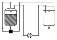
As shown in Fig. 3, the non-stirring device is installed in the resin tank of 3000 mm×2000 mm. In the process of transportation, supplementary water flows in from the top inlet of the tank, and the inflow speed is set to 0.0152 m/s. After resin and water are mixed, they are flow out freely from the top nozzle outlet of the non-stirring device.

|
Fig.3 Hydrodynamic calculation and analysis model without stirring device |
In this paper, four groups of non-stirring devices with different sizes are set up, and the resin transport concentration is analyzed. In order to compare the simulation results with the experimental results, the pipe size parameters set in the model are set with reference to the experimental parameters. From the calculation results shown in Table 3, it can be seen that there is a close relationship between the resin transport concentration without stirring device and the pipeline size parameters without stirring device when the outflow velocity at the mixing outlet is kept constant.
| Table 3 Results of fluent analysis without stirring unit |
As shown in Fig. 4, 250 L resin and 300 L water are filled in the 500 L resin tank, and the water pipe of the non-stirring conveying device is 900 mm DN20 stainless steel pipe with elbow, which verifies the feasibility of the non-stirring conveying device. In this paper, by adjusting the pipe size of the resin pipe connected to the mixing chamber of the non-stirring device, the numerical transport concentration is changed, and the correlation between the non-stirring transport concentration and the device size is verified. In the experiment, the measuring cup is used to sample, and the resin concentration is estimated. The data are recorded in Table 4.

|
Fig.4 Test flow chart of built-in no stirring conveying device |
| Table 4 Verification of the effect of conveying concentration without built-in agitator |
The comparison between Table 3 and Table 4 shows that the experimental values of the non-stirring conveying device are in good agreement with the calculated values. Therefore, in the process of type selection of non-stirring devices of different specifications in engineering practice, the resin transport concentration of non-stirring devices can be analyzed by numerical simulation, and optimization suggestions can be put forward. As shown in Fig. 5.

|
Fig.5 Comparison between experimental and calculated values of resin transport concentration without stirring device |
3 Research on Application of Non-stirring Device-Scientific Research Prototype
When the conveying system is running normally, the resin conveying efficiency is related to the conveying concentration and flow rate. Set the transport concentration as C, the transport flow rate is Q, the clogging probability is K(C), it is closely related to the medium concentration C, transport efficiency is η, there are:
| $ \eta=(1-K(C)) \cdot Q \cdot C $ |
Eq.(1) shows that the higher the concentration of the resin in the solid-liquid two-phase flow, the greater the flow resistance, the higher the probability of resin clogging. Let K (C) have critical clogging thresholds C1 and C2, When the resin concentration is lower than C1, K(C) = 0, that is, it will not be blocked; When the resin concentration exceeds C2, K(C) =1, which is bound to clog, as shown in Fig. 6.

|
Fig.6 Resin transport efficiency curve |
The critical thresholds C1, C2 and the optimum transport concentration are related to the equipment performance and transportation process of the conveying system. Engineering and tests show that there is a risk of blockage in the conveying equipment when the concentration of the resin is more than 40%. As shown in Fig. 6, in the current transportation process, there is an optimal resin transport concentration. After exceeding the optimal transport concentration, with the increase of the transport concentration, the clogging probability increases and the transport efficiency decreases. On the other hand, under the assumption that there is no blockage, the resin transport efficiency will continue to increase with the transport concentration. Therefore, increasing the resin transport concentration without blockage is an effective way to improve the resin transport efficiency.
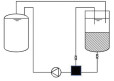
3.1 Selection of Installation Mode of Non-stirring Device for Waste Resin in Nuclear Power PlantThere are two installation methods for non-stirring device: built-in and external. Above we simulated the built-in transport through FLUENT, and in this section the external transport is simulated. As shown in Fig. 7, during transportation, supplementary water flows through the irrigation top inlet, and the inflow speed is set to 0.015 m/s; the resin and water are mixed and flowed out freely through the outlet on the right side of the non-stirring device. The selection of parameters in this section is based on the same basis as in Section 2 of this article.

|
Fig.7 Hydrodynamic calculation and analysis model of external agitator-free device |
As shown in Table 5, the internal and external simulation results of the non-stirring device show that the built-in and external devices have no obvious effect on the resin transport concentration. Due to the determination of the size parameters of the built-in non-stirring device, the resin transport concentration cannot be changed according to the actual working conditions; In addition, due to the existence of radioactivity in engineering applications, if problems occur, it is not easy to deal with and replace, so this paper focuses on the application of external non-stirring device.
| Table 5 Internal and external simulation analysis of non-stirring device |
3.2 Experimental Verification of Conveying Concentration Control Without External Stirring Device
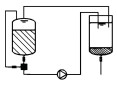
As shown in Fig. 8, through experimental research, the mixing chamber of the resin pipe and the water pipe is installed outside the resin tank, the resin pipe is connected to the resin outlet at the bottom of the resin tank, the water pipe is covered in the tank, and the mixing pipe is used as the outlet of the mixed material of resin and water. In order to ensure continuous transportation, a water pump is added between the two resin tanks to transport the return water.

|
Fig.8 Test flow chart of external no stirring conveying device |
The research conditions and test data are shown in Table 6.
| Table 6 effect of water pipe valve opening on transportation efficiency without stirring device |
The test data show that it is feasible to transport resin without stirring device. External non-stirring device water pipe valve and resin pipe valve are controlled independently, with the following characteristics:
1) At the initial stage of transportation, the water valve is opened for pre-flushing of the conveying system; after the operation of the system is stable, the resin valve is opened for conveying, which completely solves the clogging problem caused by the high initial conveying concentration;
2) Through the adjustment of the opening of the water valve, the on-line adjustment of resin transport concentration can be realized;
3) After the resin conveying stage is completed, the resin valve is closed, the water valve is kept open, and the flushing of the conveying system can be realized without stopping the pump;
4) Under the premise that the conveying system is certain and not clogged, the higher the conveying concentration is, the higher the conveying efficiency is.
3.3 Study on Optimization of External Non-stirring Transportation ProcessIn Section 3.2 concentration control verification test of external non-stirring device, by controlling the valves on the resin pipe and water pipe, the external non-stirring device has good on-line concentration regulation performance and wide regulation range. In order to ensure that the water valve is not clogged, the minimum opening of the water valve is 45 °, and the resin transport concentration is 40%, which limits the transport efficiency. The fundamental reason for the blockage failure of resin transportation is the increase of pipeline system resistance caused by the increase of the viscosity of the conveying medium, at the same time, the resistance caused by the resin passing through the pump leads to the decrease of the effective output power of the pump body, which directly leads to the blockage of the pump.
Increasing the upper limit of the concentration of the conveying system can improve the efficiency of resin transportation. Therefore, this paper optimizes the conveying process to increase the upper limit of resin concentration, which includes two directions of research:
1) The optimization of the working medium of the conveying equipment as the basic research to solve the clogging fault.
2) Comparison between positive pressure transportation and negative pressure transportation as an advanced study of system optimization.
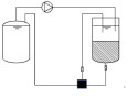
In this paper, the technical optimization research and development are carried out on the basis of resin agitation-free transportation, and the advanced schemes such as resin conveying equipment working medium for water and positive pressure transportation are creatively adopted, and the experimental study on resin transportation between resin tank and pressure tank is carried out. The experimental data are shown in Table 7.
| Table 7 Comparative test data of resin transport process optimization |
Of which:
Condition 1: Resin tank outside without stirring negative pressure conveying resin to pressure tank, and the working medium of the pump is a mixture of resin and water.
Condition 2: Resin tank outside without stirring negative pressure conveying resin to pressure tank, and the working medium of the pump is water.
Condition 3: Pressure tank outside without stirring negative pressure conveying resin to resin tank, and the working medium of the pump is a mixture of resin and water.
Condition 4: Pressure tank outside without stirring positive pressure conveying resin to resin tank, and the working medium of the pump is water.
As can be seen from Table 7, through the combination of external non-stirring conveying device and pressure tank, we can not only avoid the contact between conveying equipment and resin to solve the clogging problem, but also have excellent resin concentration regulation and high transportation efficiency.
The experimental data of resin pump transportation show that in Conditions 1 and 3, the working medium of the conveying equipment is a mixture of resin and water. When the resin concentration exceeds 40%, it is difficult to transport; when the resin concentration reaches 50%, it is easy to block. In working Conditions 2 and 4, the working medium of the conveying equipment is water, and the resin concentration can still be transported normally when the concentration of resin reaches 70%.
The test data of positive pressure and negative pressure transportation show that the transportation efficiency of Condition 4 (positive pressure resin but pump) is 170% higher than that of Condition 3 (negative pressure resin pump), The transportation efficiency of Condition 4 (positive pressure resin but pump) is 40% higher than that of Condition 2 (negative pressure resin pump).
As a result, it can be seen that when the resin is not pumped, not only the probability of blockage during resin transportation will be greatly reduced, but also when negative pressure transportation is used at the same time, the transport efficiency of the pump with water as the working medium will also be higher than that of the pump with resin and water as the working medium. In addition, the conveying efficiency of the pump is better than that of negative pressure when using positive pressure.
4 Research on Application of Non-stirring Device-engineering Prototype[14] 4.1 Design of External no Stirring Conveying SystemThe relationship between resin transport efficiency η and clogging probability K(C) and transport concentration is proposed in Fig. 6 above, The engineering prototype of the external agitation-free conveying system designed in this paper can not only adjust the resin concentration in the range of 0-100%, but also further reduce the risk of clogging through backwashing pipeline, flushing pipeline, water circulation process and so on. The water pipes/ flushing pipes, resin pipes, mixing pipes and backwashing pipes in the 002BA external non-stirring positive pressure conveying system are marked in Fig. 9. The same piping system is designed for the negative pressure conveying system on the 001BA/003BA.

|
Fig.9 Flow chart of external no stirring conveying engineering prototype |
4.2 Verification Study of External no Stirring Conveying System 4.2.1 Verification of concentration regulation in positive pressure transportation
In order to verify the engineering application of external agitation-free transportation, an engineering prototype test bench at 1:1 was set up according to the resin conveying system of nuclear power plant, and a large number of experimental studies were carried out around the transport concentration regulation performance and non-clogging process.
In this paper, the working conditions in Table 8 have been verified not less than 5 times, and no blockage has occurred. The experimental results show that external agitation-free transportation can be used in engineering. The use of external non-stirring positive pressure transportation, resin but pump technology, resin transport concentration of more than 80% can still be transported normally.
| Table 8 Test data of external non-stirring positive pressure transportation of engineering prototype |
4.2.2 Analysis of positive pressure conveying efficiency
It can be seen from Table 8 that in the process of positive pressure transportation, because the working medium of the conveying equipment is always water, there is no inverse function relationship between the transport flow Q of the system and the resin transport concentration C, and the blockage probability function K(x) has always been 0. As a result, the efficiency curve of the conveying process is obtained, as shown in Fig. 10. Transport efficiency ratio in the figure = current flow rate × current resin concentration/(rated flow rate × 100%).

|
Fig.10 External non-stirring positive pressure conveying efficiency curve |
According to Fig. 10, it can be seen that with the increase of resin transport concentration, the transportation efficiency increases without blockage of the pipeline. When the resin concentration is less than 50% or higher than 55%, the transport efficiency increases faster with the increase of resin concentration, while when the resin concentration is in the range of 50%-55%, the transport efficiency increases less obviously with the increase of resin concentration. Therefore, under the premise of ensuring that the pipeline is not clogged, the higher the resin transport concentration, the better.
5 Advantages of no Stirring Device 5.1 Stable, Reliable and Safe Transportation ProcessStable: The analysis in Section 2.2 shows that when the surface roughness, equivalent length and pipe diameter of resin pipe and pipe are constant, the resin transport concentration is relatively stable, which is the obvious characteristic of relative stirring transportation without stirring conveying device. For the external non-stirring device, after determining the length and diameter of the pipe, as long as the opening of the valve is kept unchanged, the resin can be transported at a stable concentration, so as to achieve the following purposes:
1) Effectively solve the problem of pipeline blockage caused by uneven mixing;
2) Resin metering is realized through transport flow rate and transport concentration.
Reliable: External non-stirring is a built-in non-stirring improvement scheme, through the resin pipe and water pipe installed on the control valve, can achieve the following functions: On the basis of ensuring the stability of the transport concentration, it has the characteristic that the transport concentration can be adjusted. Through the valve control, the water valve is opened first, and the system is stable and then the resin valve is opened to transport resin, which effectively solves the problem of pipeline blockage caused by resin deposition and lack of stirring at the bottom of the tank. Fig. 11 shows the changing trend of conveying resin concentration during the opening of the engineering prototype resin valve. "50%, 20%" in the curve indicates that the resin transport concentration is 20% when the opening of the resin valve is 50%.

|
Fig.11 Change of resin concentration when opened by external no stirring resin conveying valve |
Safe: The non-stirring conveying device is composed of three entrances and a mixing chamber. Compared with other stirring transportation, it does not need to be equipped with external power equipment such as air compressor, circulating mixing pump or agitator. Simple structure and high security: The device can be maintenance-free. Waste resin from nuclear power plant is generally highly radioactive. Maintenance-free components not only improve the transmission efficiency of the system, but also reduce the radiation dose received by maintenance personnel, and improve the safety of resin transportation process. No stirring device can be completely controlled by only two valves on the resin pipe and water pipe, and the operation of resin transportation is simple; At the same time, it has good remote operation performance to avoid operators working in irradiation environment.
5.2 Increase in Resin Loading RateThe use of stirring-free transportation does not need to stir the resin storage tank as a whole, and the resin loading capacity of the resin storage equipment does not need to be taken into account, so the resin storage equipment can further increase the loading capacity. The resin storage equipment can be raised to at least 80%, and the resin storage tank of the same volume can carry more waste resin than the existing stirring transportation in the nuclear power plant.
5.3 Conveying Process is Environmentally FriendlyThe agitation-free conveying device has higher controllability, economy, safety and higher environmental protection performance at the same time.
The built-in non-stirring device does not need to add additional pipeline system and power source, thus reducing the production of radioactive waste.
With the application of the built-in non-stirring device and no moving parts, the resin tank can be completely closed, and the good tightness can be maintained even under high pressure, thus reducing the leakage of radioactive material.
The water circulation process without stirring device and pressure tank are adopted, and the working medium is only the initial water in the tank and the resin to be transported, which can ensure multiple transportations without introducing external media such as air and water, and reduce the diffusion of radioactive materials.
6 Applicable Scenarios Without Stirring Device-non-stirring Conveying Trolley 6.1 Brief Introduction of Conveying TrolleyThe shielded transfer device is used to transport the waste resin from the auxiliary plant of the nuclear power plant to the QX plant. At present, the special shielding equipment used in China adopts stirring transportation mode, which has the risk of blockage, and the resin concentration can not be controlled in the transportation process. In order to optimize this problem, this paper gives full play to the advantages of non-stirring transportation, and puts forward the process scheme of non-stirring conveying trolley, as shown in Fig. 12.

|
Fig.12 General flow chart of non-stirring conveying trolley for waste resin |
The key components of the non-stirring conveying trolley include buffer tank (optional), resin tank (airtight), conveying equipment, external non-stirring device and valve. Compared with the shielded transfer device used in Hualong No.1, the stirring parts are removed, and the following functions can be achieved:
1) Loading the waste resin from the NX plant into the resin tank through the conveying equipment and resin input pipeline;
2) Transfer the waste resin from the resin tank to the QX plant through transport equipment (or buffer tank) and resin output pipeline;
3) It can realize that the working medium of the conveying equipment is always water and avoid blockage;
4) No stirring device is a maintenance-free static part, which is safer than stirring parts;
5) No radioactive waste gas is emitted throughout the process, which is more environmentally friendly;
6) Support negative pressure transportation and positive pressure transportation.
6.2 Loading and Unloading of TrolleyFig. 13 shows the loading process of the no stirring transport trolley:

|
Fig.13 Waste resin without mixing conveying cart loading flow chart |
1) The resin tank of the conveying trolley is initially full of water;
2) If the resin storage tank is airtight, it is transported under positive pressure: The conveying water in the resin tank of the conveying trolley is transported to the resin storage tank through "pipeline 001→conveying equipment→pipeline 002→pipeline 104 ", the storage tank to form a micro positive pressure so that the storage tank of resin through the "102 pipeline→ 103 pipeline→ 003 pipeline" transport to the cart resin tank.
3) If the resin storage tank is not airtight, it will be transported under negative pressure: the process is the same as above.
4) After the transportation is completed, if the process system does not allow excess water storage, the water is transported through the cache of "104 pipeline→002 pipeline→011 pipeline→012 pipeline→001 pipeline→resin tank→021 pipeline→buffer tank".
Fig. 14 shows the unloading process of the no stirring transport trolley:

|
Fig.14 Unloading flow chart of waste resin no stirring conveying trolley-1204129475 |
1) The resin receiving tank is initially full of water;
2) Through the "202 pipeline→002 pipeline→011 pipeline→ conveying equipment→012 pipeline→001 pipeline", the water in the receiving tank is transported to the resin tank of the conveying trolley, and a micro positive pressure is formed to transport the resin in the resin tank to the receiving tank through the "004 pipeline→005 pipeline→201 pipeline". This process is positive pressure conveying, conveying equipment working medium is always water.
7 ConclusionsUneven resin mixing, difficult control of transport concentration and blockage of conveying equipment or pipes have always been difficult problems for resin transportation in nuclear power plants. Starting from a new concept, this study puts forward the feasibility of non-stirring transportation, and studies the stability and controllability of non-stirring conveying concentration through scientific theoretical calculation and a large number of experimental verifications. The safety and maneuverability of the non-stirring device are confirmed, and a set of process schemes with conveying concentration up to 80% without blockage is summarized:
1) Main external non-stirring device: Realize on-line adjustment of resin transport concentration to ensure smooth transportation.
2) Conveying process of main resin without pump: Set up a buffer tank upstream or downstream of the pump to transport resin through negative or positive pressure. The working medium of the pump is water and the pump will never be blocked.
3) Auxiliary backwash line: It is used for regular loosening, preventing hardening and solving the blockage caused by the deposition of resin between the conveyer port and the valve.
4) Auxiliary flushing line: Realize the continuous pump flushing after the completion of transportation, and thoroughly solve the problem of resin deposition blockage in the pump caused by stopping pump flushing (especially important for screw pumps).
5) Auxiliary pre-flushing line: Before transportation, the pipeline is pre-washed and the transportation system is filled with water, which makes the system run stably and reduces the clogging risk caused by the initial transportation of high concentration of resin.
Based on the research results of non-stirring device, this paper further puts forward the development scheme of waste resin non-stirring conveying trolley. At the same time, as a result of innovative technology, the non-stirring device can be widely used in the design improvement of waste resin transportation system in nuclear power plant and the pipeline transportation of solid particles such as mud and activated carbon. The promotion of this technology will provide a safer, more energy-saving, efficient, stable and controllable working environment for the transportation process of waste resin in nuclear power plants.
| [1] |
China Nuclear Power Engineering Co., Ltd. Solid Waste Treatment System Handbook. Beijing: China Nuclear Power Engineering Co. Ltd, 2015.5-35.
(  0) 0) |
| [2] |
Qu Xiaorui. Research Report on Stirring and Transportation Technology of Waste Resin. Beijing: China Nuclear Power Engineering Co. Ltd, 2017.1-39.
( 0) |
| [3] |
Ni Jinren, Wang Guangqian. Comparison of two basic methods for studying solid-liquid two-phase flow. Sediment Study, 1992(3): 95-102. ( 0) |
| [4] |
Qiu Hao, Cao Bin, Xia Jianxin. Calculation of critical flow rate of non-deposition in hydraulic transportation of coarse particle materials pipeline. Journal of Water Conservancy and Water Transport Engineering, 2016(6): 103-108. ( 0) |
| [5] |
Fei Xiangjun. Prediction of friction loss in hydraulic transportation of solid pipelines. Journal of Hydraulics, 1986(12): 20-29. ( 0) |
| [6] |
Durand R. The hydraulic transportation of coal and other materials in pipes. Colloq National Coal Board, London, 1952.123-130.
( 0) |
| [7] |
Dai Jilan. Two Flows with Transition Layers in Pipes. Beijing: Tsinghua University, 1985.
( 0) |
| [8] |
Wilson K C, Clift R, Addie G R, et al. Effect of broad particle grading on slurry stratification ratio and scale-up. Powder Technology, 1990, 61(2): 165-172. DOI:10.1016/0032-5910(90)80151-N ( 0) |
| [9] |
Sundqvist A. Slurry pipeline friction losses for coarse and high density industrial products. Powder Technology, 1996, 89(1): 19-28. DOI:10.1016/S0032-5910(96)03149-X ( 0) |
| [10] |
Xia Jianxin, Ni Jinren, Huang Jiazhen. Pressure loss of manganese nodules during vertical pipeline transportation. Sediment Research, 2002(2): 23-28. ( 0) |
| [11] |
Ye Jian, Xia Jianxin. Study on Motion State and Resistance Variation of Coarse Particles in Complex Pipeline Transportation Process. Beijing: Minzu University of China, 2011.
( 0) |
| [12] |
Wang Jingduo. Fluid Motion Through Valves, Fittings, and Pipelines. Shanghai: Shanghai Scientific and Technical Literature Press, 1992.
( 0) |
| [13] |
Zhang Hongliu. Principles of Chemical Engineering (Volume Ⅰ). Shanghai: East China University of Technology Press, 2006.
( 0) |
| [14] |
Li Jianfa. Nuclear Power Plant Waste Resin Mixing and Conveying Project Test Report. Beijing: China Nuclear Power Engineering Co, LTD, 2019.1-69.
( 0) |