The snake-like robot is an under-actuated robot composed of multiple rigid bodies. Because the snake-like robot (SLR) has many degrees of freedom, it is very suitable to move in the narrow and unstructured environment[1-2]. More degrees of freedom increase the flexibility of SLR, but it brings difficulties to the research of SLR. Because USLR is influenced by the hydrodynamic force during its motion, it is more difficult to study than land snake-like robot. Due to the superiority of USLR in ocean observation (such as detection of underwater oil pipeline and search for victims in shipwreck), it has attracted the attention of researchers.
Considering the cost and danger of underwater experiments, computer modeling and simulation is a very effective method for USLR research. Nia et al.[3] gives a modeling method of SLR based on passive wheel and Kane's equations. This method is not suitable for USLR, because the hydrodynamic force does not satisfy the characteristics of passive wheel. They also did not give the detailed expressions of dynamic derivation process of USLR. Due to the need of control algorithm design and simulation platform construction, this paper briefly introduces the modeling process of USLR. A more detailed derivation can be found in our previous work[4].
The USLR essentially belongs to the category of bionic robots. It is reasonable and effective to introduce the research results of animal motion into the motion control design of USLR. It has been found that the underlying motor control of animals is done by CPG[5-8]. Therefore, many researchers have taken CPG into the rhythmic motion control of robots[9-15]. Many researchers have also researched locomotion of SLR controlled by CPG[16-18]. However, the relation between CPG parameters and snake-like robot locomotion, and the relation between adaptive motion and CPG-Based control is seldom discussed. Sato et al.[19-20] have studied adaptive motion of SLR to change ground friction, but they have not given a clear criteria of optimal locomotion into consideration. Wu and Ma[21] proposed curvature adaptive principle and discussed how CPG parameters influence locomotion efficiency in their simulation platform, but their research only applies to SLR with wheels on land, and they did not give the mathematic model of SLR.
Although CPG is widely used in walking and creeping control of various kinds of robots, it is rarely used in swimming control of USLR. Ijspeert et al.[22] studied swimming of salamander. Crespi and Ijspeert[23] researched optimal motion of amphibious snake robot. But they did not discuss how the CPG parameters and hydrodynamic coefficients influence the swimming speed and how CPG-Based control realize the adaptive swimming to the change of environment.
In this paper, we established a simulation platform, and analyzed the factors that affect the motion of USLR. By means of simulation, a method is given to realize adaptive swimming of USLR.
1 Kane Dynamic Model of USLRIn this section, Kane Dynamics is introduced to establish dynamic modeling of n-link USLR. The whole modeling process of USLR is shown and the important parts are analyzed in detail.
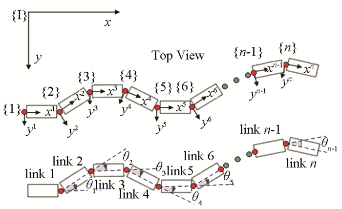
1.1 Coordinate System of USLRThe USLR is composed of n links, so it has n-1 single-degree-of-freedom joints (Fig. 1). Define the generalized coordinates of the USLR as
| $\boldsymbol{q}=\left[\begin{array}{llllll} x^1 & y^1 \psi & \theta_1 & \theta_2 & \cdots & \theta_{n-1} \end{array}\right] $ | (1) |
|
Fig.1 Frames assignment on the underwater snake-like robot |
where x1, y1 are global coordinates of the tail of USLR; ψ is orientation of the tail of USLR; the remaining coordinates are the joint angle of USLR.
The generalized speeds of USLR can be expressed as
| $ u_1=\dot{x}^1, u_2=\dot{y}^1, u_3=\dot{\psi} $ | (2a) |
| $ \begin{gathered} u_r=\dot{\theta}_{r-3}(r=4, 5, \cdots, n+2) \end{gathered} $ | (2b) |
where
In this paper, the planar swimming of USLR and the joint rotates on the z axis are studied.
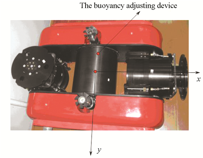
1.2 Hydrodynamic Forces of USLRBecause USLR swims slowly, its hydrodynamic force mainly consists of three parts[24]. Because our module is symmetric (Fig. 2) and moves slowly, lift force can be neglected[24].
|
Fig.2 Body segment of the underwater snake-like robot |
The buoyancy of the link j can be expressed as
| $ \boldsymbol{B}^j=-\rho V^j \boldsymbol{g}, (j=1, 2, \cdots, n) $ | (3) |
where ρ is the density of the fluid; Vj is the volume of the fluid displaced by the link j; g is gravitational acceleration.
Drag forces are mainly determined by flow turbulence, body shape, and skin roughness[24]. Hence, the drag force can be computed in the following vector form[25]:
| $\boldsymbol{F}_d^j=-\frac{1}{2} \rho \left[ \begin{matrix} C_{\text{d}x}^{j}A_{\text{px}}^{j} & {{|}^{j}}v_{x}^{j} & {{\left. {} \right|}^{j}}v_{x}^{j} \\ C_{\text{d}y}^{j}A_{\text{py}}^{j} & {{|}^{j}}v_{y}^{j} & {{\left. {} \right|}^{j}}v_{y}^{j} \\ C_{\text{d}z}^{j}A_{\text{pz}}^{j} & {{|}^{j}}v_{z}^{j} & {{\left. {} \right|}^{j}}v_{z}^{j} \\ \end{matrix} \right], (j=1, 2, \cdots, n) $ | (4) |
where Apxj, Apyj and Apzj are the projected areas to the xj, yj and zj axes; jvxj, jvyj and jvzj are velocities of link j; Cdxj, Cdyj, and Cdzj are drag coefficients.
The drag moments can be expressed as[25]
| $ \boldsymbol{M}_{\mathrm{d}}^j=-\frac{\rho}{64}\left[ {\begin{array}{*{20}{c}} {{{\left. {\left( {C_{{\rm{d}}y}^jH_j^4 + C_{{\rm{d}}z}^jW_j^4} \right){L_j}} \right|}^j}\omega _x^j{|^j}\omega _x^j}\\ {\left( {C_{{\rm{d}}x}^jH_j^4 + C_{{\rm{d}}z}^jL_j^4} \right){W_j}{\mid ^j}\omega _y^j{|^j}\omega _y^j}\\ {{{\left. {\left( {C_{{\rm{d}}x}^jW_j^4 + C_{{\rm{d}}y}^jL_j^4} \right){H_j}} \right|}^j}\omega _z^j{|^j}\omega _z^j} \end{array}} \right], \\ (j=1,2, \cdots, n) $ | (5) |
where Lj, Wj and Hj are listed in Table 1; jωxj, jωyj and jωzj are angular velocity of link j.
| Table 1 Geometric parameters of link |
The added inertia forces and added inertia moments are expressed in vector form as[25]
| $ \boldsymbol{F}_a^j=-C_a^j \rho V^{j j} \boldsymbol{a}_{\mathrm{cm}}^j $ | (6a) |
| $ \boldsymbol{M}_a^j=-C_A^j\left[\begin{array}{cc} I_{x x f}^j{ }^j {\alpha}_x^j \\ I_{y y f}^j{ }^j {\alpha}^j{ }_y \\ I_{z z f}^j{ }^j \alpha^j{ }_z \end{array}\right] $ | (6b) |
where Caj and CAj are coefficient relating to added inertia; ρVj is the mass of water; acmj is acceleration of link j; Ixxfj, Iyyfj, and Izzfj are the central moment of inertia of the fluid with the same volume of the link j; jαxj, jαyj and jαzj are angular acceleration αj of link j in xj, yj and zj directions. The hydrodynamic coefficients have been obtained by towing tank experiments.
1.3 Kane Dynamic ModelThe intermediate variable can be defined as follows:
| $ \xi_n=\left\{\begin{array}{c} \sum\limits_{i=1}^{n-1} \theta_i, n>1 \\ 0, n=1 \end{array}\right. $ | (7a) |
| $\lambda_n=\psi+\xi_n, n \geqslant 1 $ | (7b) |
| $ \gamma_n=\sum\limits_{i=3}^{n+2} u_i, n \geqslant 1 $ | (7c) |
where ξn, λn, γn are intermediate variables.
The r-th nonholonomic partial velocity and partial angular velocity of link j is
| $\boldsymbol{v}_r^j=\frac{\partial \boldsymbol{v}_{c m}^j}{\partial u_r} \begin{cases}\cos \lambda_j \boldsymbol{x}^j-\sin \lambda_j \boldsymbol{y}^j, & r=1 \\ \sin \lambda_j \boldsymbol{x}^j+\cos \lambda_j \boldsymbol{y}^j, & r=2 \\ 0.5 L_j \boldsymbol{y}^j, & r=j+2 \\ L_j\left(\sum\limits_{k=1}^{j-r+2}\left(\sin \sum\limits_{l=j-k+1}^j \xi_l\right)\right) \boldsymbol{x}^j+ \\ L_j\left(\sum\limits_{k=1}^{j-r+2}\left(\cos \sum\limits_{l=j-k+1}^j \xi_l\right)\right) \boldsymbol{y}^j+ \\ 0.5 L_j \boldsymbol{y}^j, & 2<r<j+2 \\0 & r>j+2\end{cases} $ | (8) |
| $\boldsymbol{\omega}_r^j=\frac{\partial \boldsymbol{\omega}^j}{\partial u_r}=\left\{\begin{array}{l} z^j, 3 \leqslant r \leqslant j+2 \\ 0, r<3 \text { or } r>j+2 \end{array}\right. $ | (9) |
where vcmj is velocity of link j; ωj is angular velocity of link j, ξl is intermediate variable.
| $ \boldsymbol{F}^{\bar{j}} =0, \boldsymbol{T}^{\bar{j}}=0, j=n $ | (10a) |
| $ \begin{aligned} \boldsymbol{F}^{j-1} =0, \boldsymbol{T}^{j-1}=0, j=1 \end{aligned} $ | (10b) |
where
The inertia force and inertia moment can be written as
| $ \begin{aligned} & \boldsymbol{F}^{* j}=-m^j \boldsymbol{a}_{\mathrm{cm}}^j=-m^j\left[\left(L_j \dot{u}_3 \sin \xi_j-L_j\left(u_3\right)^2 \cos \xi_j+\right.\right. \\ & \sum\limits_{k=2}^{j-1}\left(-L_k\left(\gamma_k\right)^2 \cos \left(\xi_j-\xi_k\right)+L_k \dot{\gamma}_k \sin \left(\xi_j-\xi_k\right)\right)- \\ & \left.0.5 L_j\left(\gamma_j\right)^2+\dot{u}_1 \cos \lambda_j+\dot{u}_2 \sin \lambda_j\right) \boldsymbol{x}^j+\left(\dot{u}_2 \cos \lambda_j-\right. \\ & \dot{u}_1 \sin \lambda_j+L_j \dot{u}_3 \cos \xi_j+L_j\left(u_3\right)^2 \sin \xi_j+ \\ & \sum\limits_{k=2}^{j-1}\left(L_k\left(\gamma_k\right)^2 \sin \left(\xi_j-\xi_k\right)+L_k \dot{\gamma}_k \cos \left(\xi_j-\xi_k\right)\right)+ \\ & \left.\left.0.5 L_j \dot{\gamma}_j\right) y^j\right] \end{aligned} $ | (11) |
| $\boldsymbol{T}^{* j}=-\alpha^j \cdot \boldsymbol{I}^j-\boldsymbol{\omega}^j \times \boldsymbol{I}^j \cdot \boldsymbol{\omega}^j=-\boldsymbol{I}_{z j}^{{j}} \ddot{\lambda} \boldsymbol{z}_j^j $ | (12) |
where mj is the mass of link j;
| Table 2 Inertia parameters |
The generalized inertia force of link j can be written as
| $ \begin{aligned} & F_r^*=\sum\limits_{j=1}^n\left(\boldsymbol{F}^{* j} \cdot \boldsymbol{v}_r^j+\boldsymbol{T}^{* j} \cdot \omega_r^j\right), \\ & (r=1, 2, \cdots, n+2) \end{aligned} $ | (13) |
where Fr*, vrj, ωrj represent the r-th generalized inertia, nonholonomic partial velocity, and partial angular velocity, respectively.
The generalized active force of link j can be expressed as
| $ \begin{gathered} \boldsymbol{F}_r=\sum\limits_{j=1}^n\left(\boldsymbol{F}_d^j \cdot \boldsymbol{v}_r^j+\boldsymbol{F}_a^j \cdot \boldsymbol{v}_r^j+\boldsymbol{M}_d^j \cdot \boldsymbol{\omega}_r^j+\right. \\ \left.\boldsymbol{M}_a^j \cdot \boldsymbol{\omega}_r^j+\boldsymbol{T}^{\bar{j}} \cdot \boldsymbol{\omega}_r^j+\boldsymbol{T}^{j-1} \cdot \boldsymbol{\omega}_r^j\right), \\ r=(1, 2, \cdots, n+2) \end{gathered} $ | (14) |
Kane dynamic equation of USLR can be given as follows:
| $\boldsymbol{F}_r^*+\boldsymbol{F}_r=0, (r=1, 2, \cdots n+2) $ | (15) |
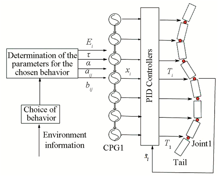
CPG-Based control architecture for swimming of USLR is illustrated in Fig. 3.
|
Fig.3 The complete control architecture of USLR |
2.1 CPG Model
The proposed CPG model can be expressed as
| $ \tau \dot{\nu}_i=-\alpha \frac{\left(x_i-x_{0 i}\right)^2+\nu_i^2-E_i}{E_i} \nu_i-\left(x_i-x_{0 i}\right)+\\ \begin{array}{r} a_{i j}\left(x_j-x_{0 j}\right)+b_{i j} \nu_j+f_i \\ \tau \dot{x}_i=\nu_i \end{array} $ | (16) |
where
| $ x_{0 i}=\left\{\begin{array}{l} x_0, 1 \leqslant i \leqslant n_c \\ 0, n_c<i<n \end{array}\right. $ | (17) |
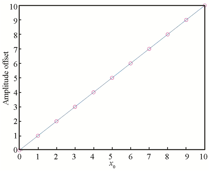
where x0 is the joint angular offset which can be used to control swimming orientation of USLR and is set to zero for swimming in straight line. If x0 is positive value, the swimming trajectory of USLR is a clockwise curve. We set parameters Ei=E, and aij= bij=0.5 for all connections and α=30 for all oscillators.
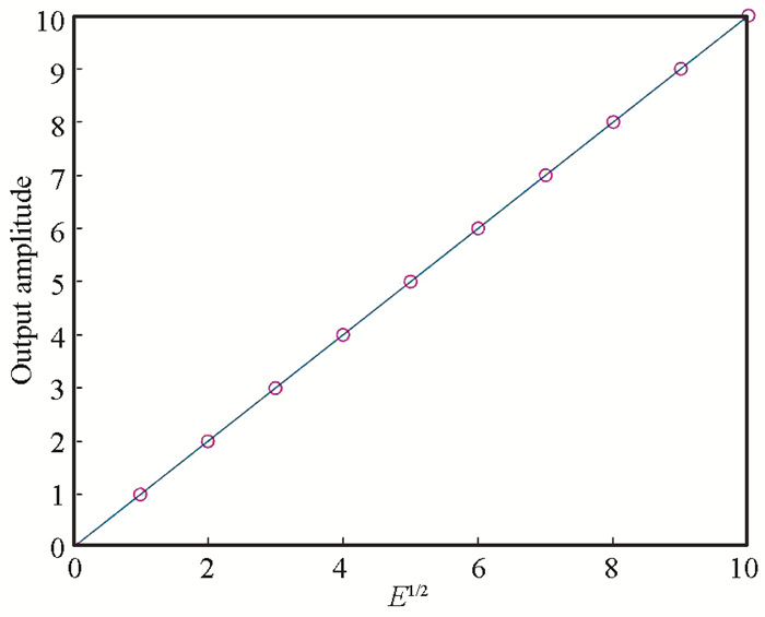
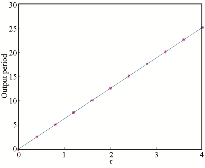
2.2 Characteristic of the CPG ParametersFrom the simulation results (Figs. 4-6), it can be seen that CPG parameters τ, E and x0i are main factors which influence the CPG output.
|
Fig.4 Relation between E and output amplitude |
|
Fig.5 Relation between τ and output period |
|
Fig.6 Relation between x0 and the amplitude offset |
2.3 CPG Output
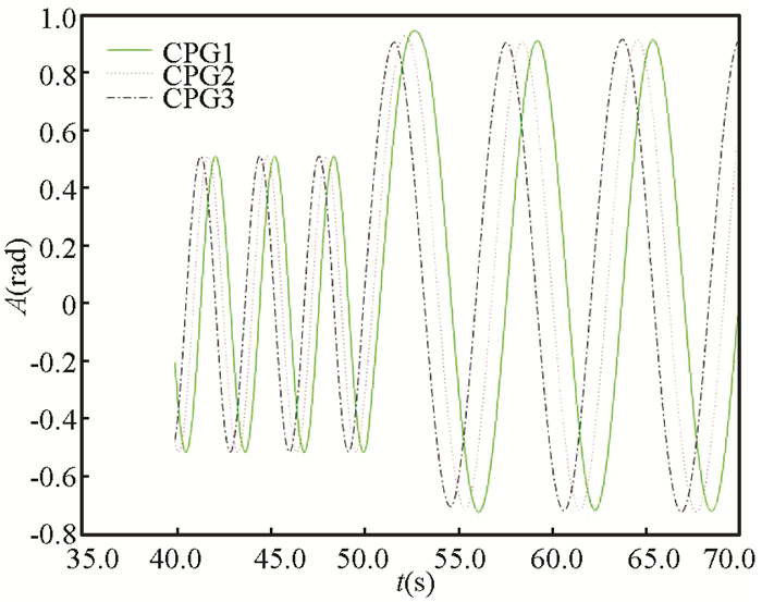
Fig. 7 illustrates how CPG reacts when the CPG parameters are abruptly varied. As the CPG model are computed online by integrating the second order differential equations, the output waves of CPG are smooth despite CPG parameters abruptly change.
|
Fig.7 Trajectories provided by the CPG (40≤t < 50, A=0.5, ω=2, x0=0;50≤t≤70, A=0.8, ω=1, nc=3, x0=0.1) |
Another important advantage of the CPG is that it can generate desired waves through integrate feedback terms to CPG model. In this paper, fi=0 is set for all oscillators and the rest CPG parameters are modulated to generate the desired trajectories (Fig. 3). PID controllers can be used to improve the tracking ability of CPG output waveform (Fig. 3).
3 Swimming of a CPG-Controlled USLRIn this section, the controller is designed for USLR based on CPG. Taking the 7-link USLR as an example, a simulation platform is built in Matlab/Simulink environment to verify the effectiveness of the controller. An experiment is also conducted to verify swimming along the straight line of underwater snake-like robot consisted of 3 links.
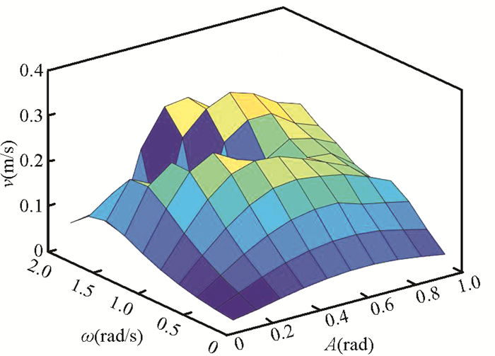
3.1 Effects of the CPG ParametersFig. 8 shows how the CPG parameters influence the swimming speed of the underwater snake-like robot. When ω changes from 0.2 rad/s to 1.6 rad/s and A changes from 0.1 rad to 1.0 rad, swimming speed increases monotonically with ω and A up to ω=1.2 rad/s and A=0.4 rad where they saturate. Maximum speed 0.237 m/s is attained. There are some points (ω=1.8, A=0.6, 0.7, 0.8, and ω=2.0, A=0.5, 0.6) whose speed is greater than 0.237 m/s. However, there are some minimum values when ω≥1.6 (refer to the hollow area in Fig. 8). It is non-steady state when ω≥1.6. The larger swing range and higher frequency of the joint will increase the angular acceleration of the link, and then increase the additional mass of the robot, so that the speed of the underwater snake-like robot becomes slower.
|
Fig.8 Simulation results under different CPG parameters |
3.2 Effects of the Hydrodynamic Coefficients
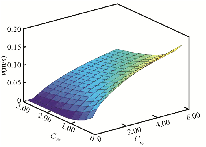
To figure out how hydrodynamic coefficients affect the speed of USLR, the swimming speed is studied with two hydrodynamic coefficients varied while the rest hydrodynamic coefficients are invariant. The hydrodynamic coefficients are mainly consisted of Cdx, Cdy, Ca and CA. Influences of these hydrodynamic coefficients on swimming speed of USLR are primarily investigated. The swimming speed of the underwater snake-like robot increases when Cdx decreases and Cdy increases, and the growth rate decreases when Cdy increases and Cdx are fixed, which can be seen in Fig. 9.
|
Fig.9 Relation between swimming speed and drag coefficients (Cdx, Cdy) |
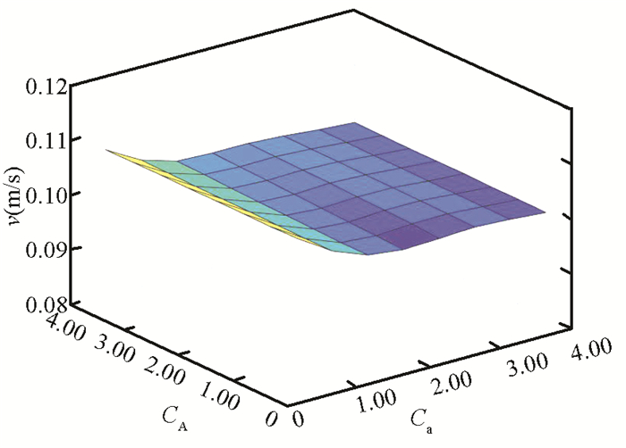
As shown in Fig. 10, it can be easily found that the speed of USLR decreases slowly when Ca changes from 0.5 to 4.0 (CA is fixed), and the swimming speed almost remains the same when CA changes from 0.5 to 4.0 (Ca is fixed). The difference between the maximum speed and minimum speed is 0.01. So the swimming speed of the underwater snake-like robot is mainly influenced by the drag coefficients Cdx and Cdy. This shows that the smaller the tangential resistance and the larger the normal resistance, the faster the underwater snake-like robot swimming. This conclusion is consistent with the movement of snakes on land.
|
Fig.10 Relation between swimming speed and added inertia coefficients |
3.3 Swimming along the Straight Line
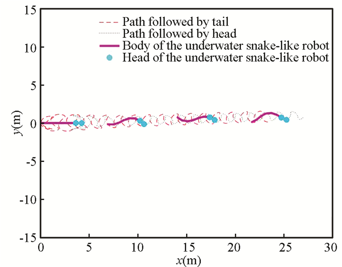
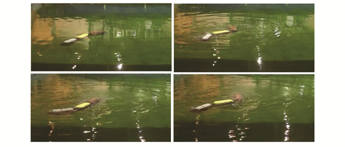
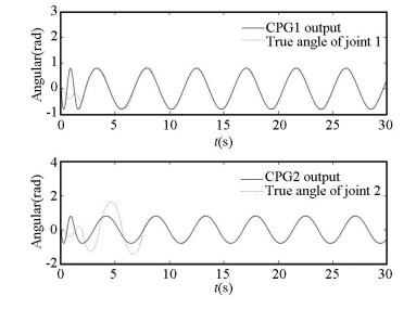
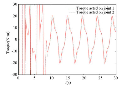
Fig. 11 shows the straight line trajectory of the USLR (x0=0). To verify CPG-Based controllers, an experiment of 3-link underwater snake-like robot swimming along the straight is conducted (Fig. 12). Due to the limitation of motor torque and the need of self-adjustment, it takes about 10 s for the underwater snake to reach a stable state (Figs. 13-14).
|
Fig.11 Swimming trajectory of USLR (A=0.5 rad, ω=0.7 rad/s, Cdx=0.6, Cdy=3, Ca=1.2, CA=1.5) |
|
Fig.12 Swimming experiment of USLR |
|
Fig.13 Comparison of CPG output and joint angle |
|
Fig.14 Control torque of motor |
3.4 Turning
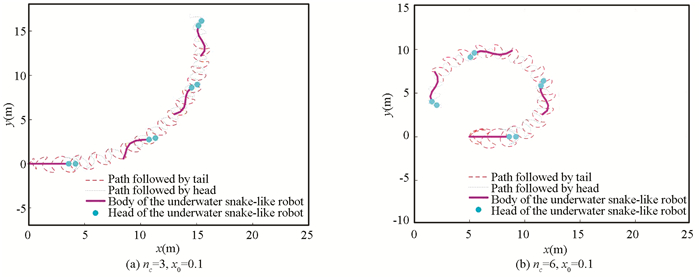
Steering ability is another important indicator of USLR. Steering ability of the USLR is determined by x0 and nc. nc is used to control the range of the offset signal x0, the larger the nc, the better the rotation effect (Fig. 15(a)-(b)).
|
Fig.15 Relation between nc and turning radius |
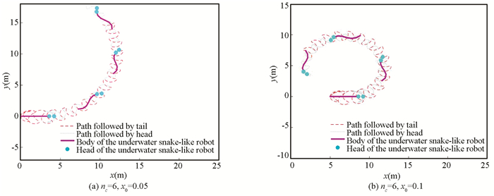
Fig. 16 verifies the effect of x0 on steering ability of USLR when nc=6, x0=0.05 and when nc=6, x0=0.1. If x0 is set greater, the maneuverable is stronger.
|
Fig.16 Relation between x0 and turning radius |
4 Adaptive Swimming to Underwater Environment Change
Essentially, the snakes can change body shape to adapt to different terrains. To figure out the CPG parameters that are related to adaptive swimming of the underwater snake-like robot, the swimming with the experimental optimization is discussed in our simulation platform. Herein, experiments with different drag coefficients are considered to obtain the maximum swimming speed of the underwater snake-like robot; switching between different swimming modes is implemented to avoid obstacles.
Based on the maximum swimming speed criterion, hydrodynamic characteristic of prototype module are optimized, and optimal CPG parameter is researched in certain hydrodynamic forces. Section 3 shows that drag force is the main reason affecting the swimming speed. So, drag coefficients can be made to vary in a large range (from 0.3 to 3.0).
4.1 Maximum Swimming Speed to Different Drag CoefficientsWhen drag coefficients change, the locomotion curvature of USLR can change correctly through changing relevant CPG parameters. The amplitude A can be used to obtain the desired locomotion curvature of USLR (curvature adaptive principle).
In this simulation, the optimal swimming curvature of USLR is found. The relation between drag coefficients, CPG parameter A and swimming speed along the forward direction is illustrated in Fig. 17(a). Based on the maximum swimming speed criterion, the optimal amplitude is 0.5 rad.

|
Fig.17 Simulation results under different hydrodynamic coefficients |
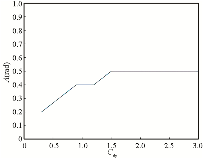
In another simulation, the drag coefficient Cdx is set as Cdx=0.6, and the drag coefficient Cdy varies from 0.3 to 3.0. Meanwhile, parameter A(amplitude of CPG output) varies from 0.1 to 1.5 to search the optimal swimming curvature of the underwater snake-like robot. Based on the maximum swimming speed criterion, the optimal amplitude relative to the drag coefficients and the CPG parameter A is obtained in Fig. 17(b). For each Cdy, there is a corresponding A to make the underwater snake-like robot get the maximum swimming speed. Therefore, the value of CPG parameter A to generate the maximum swimming speed is optimized as shown in Fig. 16, where the drag coefficient Cdy changes from 0.3 to 3.0 with the interval of 0.3.
In this section, the relation between curvature of body and adaptive swimming are mainly researched. The curvature of body is determined by CPG parameterA[21]. Based on the maximum swimming speed criterion, the relation between drag coefficients and CPG parameter A is investigated. The optimal curvature of body (CPG parameter A) with experimental optimization to different drag coefficients are obtained (Figs. 17-18).
|
Fig.18 Relation between optimal A and drag coefficient Cdy |
4.2 Switching Between Different Swimming Modes
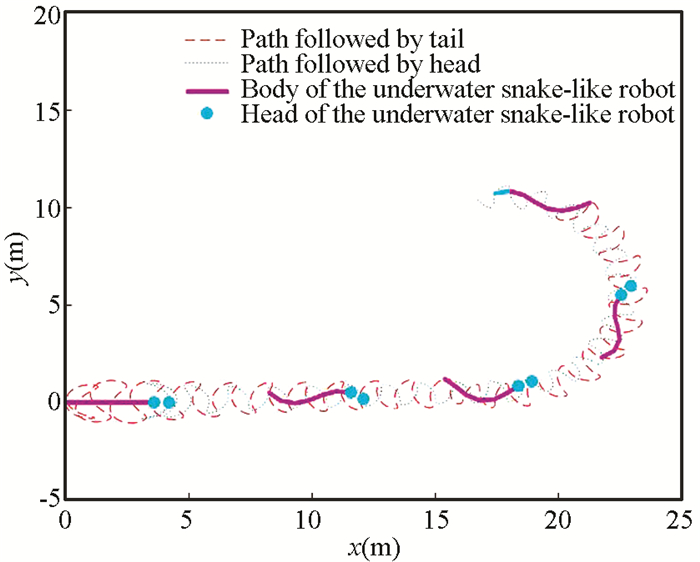
With position information of the underwater snake-like robot and a map of the underwater environment, the swimming modes can be adjusted to avoid obstacles and reach the target position. The CPG-Based controllers makes transitions between swimming along the straight line (0≤t < 100, x0=0) and turning (100≤t≤200, x0=0.1, nc=6) (Fig. 19).
|
Fig.19 Trajectory of the underwater snake-like robot when it switches swimming modes (A=0.5 rad, ω=0.7 rad/s, Cdx=0.6, Cdy=3, Ca=1.2, CA=1.5) |
5 Conclusions
A 7-link USLR simulation verification platform is built to verify the influence of CPG parameters and hydrodynamic coefficients on the swimming speed and steering ability of USLR. The swimming control strategy of USLR based on curvature adaptive principle is proposed. To examine adaptive swimming of USLR to different hydrodynamic forces, a criterion of maximum swimming speed is put forward. Moreover, the swimming of USLR is optimized in the simulation experiment based on the curvature adaptive principle and maximum swimming speed criterion. On the basis of the relation between the optimal CPG parameter and different hydrodynamic coefficients, the most adaptable swimming can be achieved. To figure out adaptive swimming of USLR to environment with obstacles, relationships between CPG parameters and steering ability have been discussed. The switching between different swimming modes is also tested. 3D simulation can be decomposed into depth and plane simulation. Depth can be controlled by buoyancy adjusting device. In this paper, the focus is on adaptive swimming in the plane.
In our future work, we will establish 3D simulation platform and conduct experiments to verify the proposed adaptive swimming strategies.
| [1] |
Mao Q Q, Zhang S, Xu J, et al. A unified representation of the actuation signals of earthworm-like locomotion robots based on travelling-wave functions. Robot, 2021, 43(2): 234-245. (in Chinese) DOI:10.13973/j.cnki.robot.200236 (  0) 0) |
| [2] |
Zhang D F. A path tracking method for the snake robot based on the path edge guidance strategy. Robot, 2021, 43(1): 36-42. (in Chinese) DOI:10.13973/j.cnki.robot.200098 (  0) 0) |
| [3] |
Nia H T, Pishkenari H N, Meghdari A. A recursive approach for the analysis of snake robots using Kane's equations. Robotica, 2005, 24(2): 251-256. DOI:10.1017/S0263574705002456 (  0) 0) |
| [4] |
Yang K, Wang X Y, Ge T, et al. Dynamic model of underwater snake-like robot using Kane's method. Journal of Shanghai Jiao Tong University, 2014, 19(2): 146-154. DOI:10.1007/s12204-014-1483-9 (  0) 0) |
| [5] |
Ijspeert A J. Central pattern generators for locomotion control in animals and robots: a review. Neural Networks, 2008, 21(4): 642-653. DOI:10.1016/j.neunet.2008.03.014 (  0) 0) |
| [6] |
McCrea D A, Rybak I A. Organization of mammalian locomotor rhythm and pattern generation. Brain Research Reviews, 2008, 57(1): 134-146. DOI:10.1016/j.brainresrev.2007.08.006 (  0) 0) |
| [7] |
Chen Z Y, Iwasaki T. Circulant synthesis of central pattern generators with application to control of rectifier systems. IEEE Transactions on Automatic Control, 2008, 53(1): 273-286. DOI:10.1109/TAC.2007.914951 (  0) 0) |
| [8] |
Carron F H, Rodriguez F B, Varona P. Bio-inspired design strategies for central pattern generator control in modular robotics. Bioinspiration and Biomimetics, 2011, 6(1): 016006. DOI:10.1088/1748-3182/6/1/016006 (  0) 0) |
| [9] |
Wang T T, Guo W, Li M T, et al. CPG control for biped hopping robot in unpredictable environment. Journal of Bionic Engineering, 2012, 9(1): 29-38. DOI:10.1016/S1672-6529(11)60094-2 (  0) 0) |
| [10] |
Park H S, Floyd S, Sitti M. Roll and pitch motion analysis of a biologically inspired quadruped water runner robot. The International Journal of Robotics Research, 2010, 29(10): 1281-1297. DOI:10.1177/0278364909354391 (  0) 0) |
| [11] |
Zhang X L, Zheng H J. Walking up and down hill with a biologically-inspired posture reflex in a quadrupedal robot. Autonomous Robots, 2008, 25(1-2): 15-24. DOI:10.1007/s10514-007-9072-5 (  0) 0) |
| [12] |
Lewinger W A, Quinn R D. Neurobiologically-based control system for an adaptively walking hexapod. Industrial Robot, 2011, 38(3): 258-263. DOI:10.1142/9789814329927_0027 (  0) 0) |
| [13] |
Seo K, Chung S J, Slotine J J E. CPG-based control of a turtle-like underwater vehicle. Autonomous Robots, 2010, 28(3): 247-269. (  0) 0) |
| [14] |
Crespi A, Lachat D, Pasquier A, et al. Controlling swimming and crawling in a fish robot using a central pattern generator. Autonomous Robots, 2008, 25(1-2): 3-13. DOI:10.1007/s10514-007-9071-6 (  0) 0) |
| [15] |
Yu J Z, Wang M, Tan M, et al. Three-dimensional swimming. IEEE Robotics and Automation Magazine, 2011, 18(4): 47-58. DOI:10.1109/MRA.2011.942998 (  0) 0) |
| [16] |
Conradt J, Varshavskaya P. Distributed Central Pattern Generator Control for a Serpentine Robot. http://people.csail.mit.edu/paulina/papers/icann03/icann03.pdf.
(  0) 0) |
| [17] |
Inoue K, Sumi T, Ma S. CPG-based control of a simulated snake-like robot adaptable to changing ground friction. Proceedings of the IEEE/RSJ International Conference on Intelligent Robots and Systems. Piscataway: IEEE, 2007. 9862736. DOI: 10.1109/IROS.2007.4399552.
(  0) 0) |
| [18] |
Matsuo T, Ishii K. Development of neural oscillator based motion control system and applied to snake-like robot. Proceedings of the IEEE/RSJ International Conference on Intelligent Robots and Systems. Piscataway: IEEE, 2007. 9862798. DOI: 10.1109/IROS.2007.4399615.
(  0) 0) |
| [19] |
Sato T, Kano T, Ishiguro A. On the applicability of the decentralized control mechanism extracted from the true slime mold: a robotic case study with a serpentine robot. Bioinspiration and Biomimetics, 2011, 6(2): 1-8. DOI:10.1088/1748-3182/6/2/026006 (  0) 0) |
| [20] |
Sato T, Kano T, Ishiguro A. A decentralized control scheme for an effective coordination of phasic and tonic control in a snake-like robot. Bioinspiration and Biomimetics, 2012, 7(1): 1-9. DOI:10.1088/1748-3182/7/1/016005 (  0) 0) |
| [21] |
Wu X D, Ma S G. Adaptive creeping locomotion of a CPG-controlled snake-like robot to environment change. Autonomous Robots, 2010, 28(3): 283-294. DOI:10.1007/s10514-009-9168-1 (  0) 0) |
| [22] |
Ijspeert A J, Crespi A, Cabelguen J M. Simulation and robotics studies of salamander locomotion. Neuroinformatics, 2005, 3(3): 171-195. DOI:10.1385/NI:3:3:171 (  0) 0) |
| [23] |
Crespi A, Ijspeert A J. Online optimization of swimming and crawling in an amphibious snake robot. IEEE Ttranactions on Robotics, 2008, 24(1): 75-87. DOI:10.1109/TRO.2008.915426 (  0) 0) |
| [24] |
Lin C C, Chen R C, Li T L. Experimental determination of the hydrodynamic coefficients of an underwater manipulator. Journal of Robotic System, 1999, 16(6): 329-338. (  0) 0) |
| [25] |
Safak K K, Adams G G. Dynamic modeling and hydrodynamic performance of biomimetic underwater robot locomotion. Autonomous Robots, 2002, 13(3): 223-240. DOI:10.1023/A:1020516108579 (  0) 0) |
 2023, Vol. 30


