2. Nanjing Research Institute of Simulation and Technology, Nanjing 210010, China;
3. Estun Automation Co., Ltd, Nanjing 210026, China;
4. Engineering Technology Center, Shenyang Aircraft Company, Shenyang 110850, China
With the continuously breakthroughs and innovations of industrial robot technology, it is widely used in automatic assembly of aerospace[1-2]. Industrial robot which can acquire high accuracy level is capable of improving the efficiency and precision of aircraft components. However, at present, the absolute accuracy of industrial robot is low due to various factors, which can only achieve millimeter level[3]. So, it is difficult to accomplish tasks in small components of aircraft which absolute accuracy level is supposed to reach 0.5 mm level[4]. According to the application of industrial robots in the field of high accuracy automatic assembly, it is very important to improve absolute accuracy of industrial robots.
The characteristics of error which influence the absolute accuracy of robot are diversified. The geometrical error during robot manufacturing and assembling process influences the robot's absolute accuracy most which accounts for 90% of all the error factors[5]. Nowadays robot kinematics calibration technology is widely used to modify error of robot geometric parameters[6-7]. Robot kinematic calibration technology mainly consists of four aspects, such as kinematics model, position and orientation measurement, parameter identification and error compensation[8]. High precision measurement system was used to acquire the position and orientation of robot end effector which is the key to identifying robot geometric parameter error. Theodolite which can acquire high precision was used to calibrate robot in Refs. [9-10]. It can improve robot absolute precision, but it cannot realize the dynamic measurement. A laser tracker was used to calibrate robot in Refs.[11-14], which improves the absolute accuracy of robot. But the laser tracker also has some disadvantages, such as the requirements of working conditions and the high costs, professionals were required to operate the device which increased the difficulty of robot calibration. A kind of new spatial measurement system is developing which based on draw-wire encoder [15]. A kind of wire which has lower inertia was used to connect robot end effector, and rotary encoder which has high revolution was used to acquire the length of the wire, it can also acquire the length of wire fast and real-time which meets the demand of different position of robot end effector. The measurement system has several characteristics such as the wide measurement range, high accuracy, low cost, easy measurement operation, and strong adaptability to the working environment, thus deep research of the kind of measurement was conducted by more and more scholars[16]. A kind of robot calibration system based on three draw-wire encoders was established by Cheng[17], which realize the calibration of industrial robot. A kind of industrial robot calibration algorithm based on single draw-wire encoder was proposed by Zhang[18], which improved the absolute accuracy of industrial robots effectively[18]. A kind of wire guiding device was designed in Ref.[19], which several pulley was used to guide the direction of wire, due to the difficulty of measuring different spatial position based on single draw-wire encoder. Therefore, the achieved length of wire is not straight line which includes an unknown arc length. But this part of unknown arc length was ignored which reduced the accuracy of calibration algorithm. The envelope angle between wire and pulley was confined to a smaller scale, which affected the calibration range of robot geometric parameter.
In this paper, a couple of angle parameters which associated with the position and orientation based on draw-wire guiding device are proposed. Pose orientation on the measurement system was established by the acquired wire length and the angle parameters which associated the position and the orientation precisely. Industrial robot geometric parameter identification model was established by the robot kinematic model, and the least square method was used to identify the robot geometric parameters. Effects of draw-wire measurement error and driving shaft error and the number of calibration points on identifying accuracy of robot geometric parameter was also studied. ER robot was used for simulation and experimental validation of the effectiveness and the high revolution of the robot calibration algorithm.
At present, there are many researches on the calibration of traditional tool coordinate system (TCP/TCF) at home and abroad.
A calibration method for robot tool coordinate system based on singular value decomposition is proposed by Liu and Niu[20]. Although this method is feasible in theory, however, the decomposition process of singular values is complicated and the code is complicated to write, on the other hand, When calibration TCF parameters, the TCF attitude and the base coordinate system of the robot need to be controlled, maintain a consistent posture, the operation is complex. A robot calibration method based on planar template is proposed by Yang[21]. A laser displacement sensor is fixed at the end of the robot. The laser displacement sensor measures the planar template in different positions and attitudes by controlling the end of the robot, the parameters of the tool coordinate system are solved by the least square fitting method.
Among these traditional calibration algorithms, some algorithms have high accuracy, but the cost is very expensive, some algorithms are not expensive but difficult to guarantee the accuracy of calibration. Therefore, a robot calibration system with pose related parameters based on wire encoder is designed in this paper. The tool coordinate system is calibrated by measuring the length, it can greatly reduce the cost of calibration while ensuring high accuracy and simple operation.
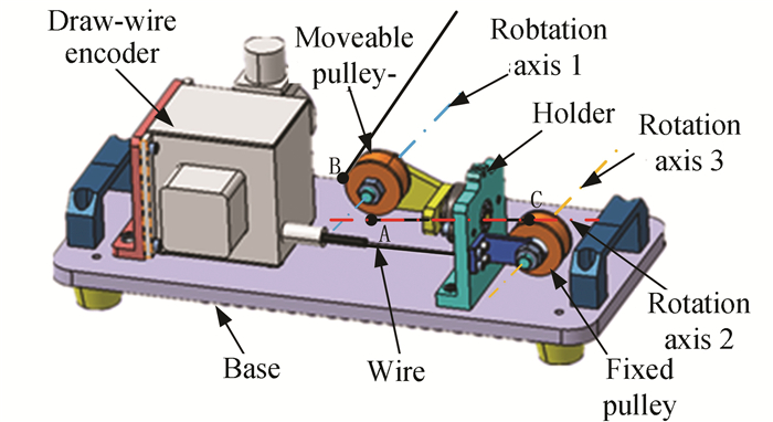
1 Robot Calibration Algorithm Based on Measurement System Including Pose and Orientation Parameters 1.1 Measurement System Based on Single draw-wire Encoder Including Pose and Orientation ParametersThe measurement system (as shown in Fig. 1) based on single draw-wire encoder mainly consists of draw-wire encoder, wire guiding device, and base. The type of the encoder is CLMS2, which the revolution can achieve 0.005 mm, and the measurement range is 2 m.
|
Fig.1 Measurement system |
A kind of draw-wire guiding device is designed to meet the demand of different spatial position measurement. As shown in Fig. 1, the upper tangent between wire and fixed pulley is point C, the upper and lower tangent of moveable pulley is point A and B respectively. The wire which was pulled out from the draw-wire encoder passed through point C, and then the wire envelope with the moveable pulley from point A along the horizontal direction. So the vertical height between points A and C is identical. Then, the wire is connected with the measured point from the upper tangent (point B). The lower tangent of the moveable pulley is constant, no matter where is the measurement points. According to this kind of measurement system, several orientation parameters are introduced to acquire the location of the measuring point.
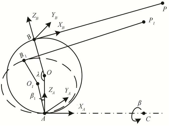
1.2 Position and Orientation Parameters of Measurement SystemAccording the moveable pulley in Fig. 1, the coordinates of measurement system is established in Fig. 2.
|
Fig.2 Measurement system coordinates |
As shown in Fig. 2, the center of moveable pulley is point O, which is the initial position of the measurement system. Point P is the measured point, and points A and B are the lower and upper tangent between the moveable pulley and the wire. The direction of wire line AC is horizontal after the guiding of fixed pulley, envelope angle between the wire and moveable pulley is λ. When the measured point P moves to point P1, the moveable pulley rotate angle β1 along line AC, and the dotted line as shown in Fig. 2 is the new location of moveable pulley. During this rotation process, the lower point has remained unchanged. Thus, the moveable pulley tangent angel λ and the rotation angel β were used to represent the location of pose P in the measurement system.
When the measurement system at initial position β=0, the base coordinate of measurement system (OAXAYAZA) was established in lower tangent point A: the direction of axis XA is horizontal to the right, the direction of axis ZA is the direction of AO at initial position which is vertical to up, according to the right hand screw rule the axis YA can be defined finally. The coordinate at the upper tangent of moveable pulley (OBXBYBZB) was also established: the direction of axis XB is from point B to point P, the direction of axis ZB is from the center of moveable pulley to the upper tangent of point B, according to the right hand screw rule the axis YB can be defined finally. The coordinate in measurement system was established according to the pose and orientation parameters λ, β. The following will introduce how to acquire the position of measured point P according to the length of wire and the pose and orientation parameters λ, β.
1.3 Position Solving Model of Measurement SystemAccording to section 1.2, the wire length L acquired by the draw-wire encoder is consisted by two parts, the radium of moveable pulley is supposed to be r:
| $ L=r \lambda+|B P| $ | (1) |
So, the position of point P in the measurement base coordinate (OAXAYAZA) can be defined as TAP:
| $ \begin{aligned} \boldsymbol{T_A^P} & =\operatorname{Rot}\left(X_A, \beta\right) \operatorname{Trans}\left(Z_A, r(1-\mathrm{c} \lambda)\right) \cdot \\ & \operatorname{Trans}\left(X_A,-r \mathrm{~s} \lambda\right) \operatorname{Rot}\left(Y_A, \lambda-{\rm{ \mathsf{ π} }}\right) \cdot \\ & \operatorname{Trans}\left(X_B, L-r \lambda\right) \end{aligned} $ | (2) |
where s and c represent sin and cos respectively. Homogeneous matrix was used to simplify calculation:
| $ \begin{aligned} & \boldsymbol{T_A^P}= \\ & {\left[\begin{array}{cccc} -\mathrm{c} \lambda & 0 & -\mathrm{s} \lambda & -r \mathrm{~s} \lambda-(L-r \lambda) \mathrm{c} \lambda \\ -\mathrm{s} \lambda \mathrm{c} \beta & \mathrm{c} \beta & \mathrm{c} \lambda \mathrm{s} \beta & r(\mathrm{c} \lambda-1) \mathrm{s} \beta-(L-r \lambda) \mathrm{s} \lambda \mathrm{s} \beta \\ \mathrm{s} \lambda \mathrm{c} \beta & \mathrm{s} \beta & -\mathrm{c} \lambda \mathrm{s} \beta & (L-r \lambda) \mathrm{s} \alpha \mathrm{c} \beta-r(\mathrm{c} \alpha-1) \mathrm{c} \beta \\ 0 & 0 & 0 & 1 \end{array}\right]=} \\ & {\left[\begin{array}{cc} \boldsymbol{K_A^P} & \boldsymbol{R_A^P} \\ 0 & 1 \end{array}\right]} \end{aligned} $ | (3) |
where, matrix KAP represents the first three rows and the first three columns of the matrix TAP, which represents the orientation of point P; matrix RAP represents the fourth row and the first three columns of the matrix TAP, which represents the 3D position of point P. The 3D position of the measurement point can be defined as four dimensional function vector F(L, λ, β), which is shown in the following:
| $ \begin{gathered} \boldsymbol{P_A}(x, y, z)=\left[\begin{array}{c} \boldsymbol{R_A^P }\\ 1 \end{array}\right]=\boldsymbol{F}(L, \lambda, \beta)= \\ {\left[\begin{array}{c} -r \mathrm{s} \lambda-(L-r \lambda) \mathrm{c} \lambda \\ r \mathrm{s} \beta(\mathrm{c} \lambda-1)-(L-r \lambda) \mathrm{s} \lambda \mathrm{s} \beta \\ (L-r \lambda) \mathrm{s} \lambda \mathrm{c} \beta-r(\mathrm{c} \lambda-1) \mathrm{c} \beta \\ 1 \end{array}\right]} \end{gathered} $ | (4) |
where, L can be acquired by draw-wire encoder; the parameter λ, β is the orientation parameter; the first three column of vector F(L, λ, β) represent the 3D positon of point P, and the fourth column of the vector is the scale factor.
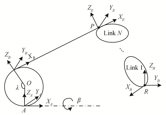
1.4 Identification Model of Robot Geometric ParameterAs shown in Fig. 3, the measured point P is the same as point E, which is the fixed point on the end effector of robot, point R is the base point of robot coordinates. The measurement system coordinates were established in Section 1.2, the end effector coordinates of robot can be acquired by D-H method.
|
Fig.3 Identification coordinates of robot calibration |
The number of robot joints can be assumed to be N, and the robot geometric parameter can be represented by vector
| $ \boldsymbol{P}_R=\boldsymbol{T}_E^R \boldsymbol{P}_E=\boldsymbol{G}(\overrightarrow{\boldsymbol{X}}) $ | (5) |
where, PR is a column vector of 4 dimension, which the first three columns represent the position of point P on the base coordinates of robot. Vector PE represents the position relationship between the measured point P and the fixed point E on the robot end effector, and
The homogeneous transfer matrix TAR from the robot base coordinates to the measurement system coordinates can be established by formula (6):
| $ \begin{aligned} & \boldsymbol{T_A^R}=\operatorname{Trans}\left(d_x, d_y, d_z\right) \operatorname{Rot}(x, A) \operatorname{Rot}(y, B) \operatorname{Rot}(z, C)= \\ & {\left[\begin{array}{cccc} \mathrm{c} B \mathrm{s} C & -\mathrm{c} B \mathrm{s} C & \mathrm{s} B & d_x \\ \mathrm{c} A \mathrm{s} C+\mathrm{s} A \mathrm{s} B \mathrm{c} C & \mathrm{c} A \mathrm{c} C-\mathrm{s} A \mathrm{s} B \mathrm{s} C & -\mathrm{c} B \mathrm{s} A & d_y \\ \mathrm{s} A \mathrm{s} C-\mathrm{c} A \mathrm{s} B \mathrm{c} C & \mathrm{c} C \mathrm{s} A+\mathrm{c} A \mathrm{s} B \mathrm{s} C & \mathrm{c} A \mathrm{c} B & d_z \\ 0 & 0 & 0 & 1 \end{array}\right]} \end{aligned} $ | (6) |
where, dx, dy, dz represent the transformation distance along axis x, y, z respectively. A, B, C represent the angle of rotation around the axis x, y, z respectively. The parameters dx, dy, dz, A, B, C are the unknown parameters. Robot geometric parameters identification equations can be achieved by simulate the Eqs.(4)-(6).
| $ \boldsymbol{T_A^R} \boldsymbol{P_A}=\boldsymbol{T_A^R} \boldsymbol{F}(L, \lambda, \beta)=\boldsymbol{G}(\overrightarrow{\boldsymbol{X}}) $ | (7) |
where, parameter L represents the length of wire, which can be acquired by the draw-wire encoder. The column of vector
The equation group (7) will be created when robot end effector moves to a position, and there will also emerge two known parameters λ, β. So, we can get n pieces of equation group (7), when the number of measured points is n, meanwhile, the number of unknown parameters is 2n+m+6, the number of equations is 3n, and the number of robot geometric parameters is m. When the number of equations is no less than the number of unknown parameters, the identification of robot geometric parameters can be achieved.
| $ n \geqslant m+6 $ | (8) |
The least square method was used in Eq.(9) to optimize the identification of Eq.(7):
| $ \begin{aligned} & \min \left(\sum\limits_{t=1}^n\left(\boldsymbol{T_A^R} \boldsymbol{F}(L, \lambda, \beta)-\boldsymbol{G}\right)^{\mathrm{T}} .\right. \\ & \left.\quad\left(\boldsymbol{T_A}^{\boldsymbol{R}} \boldsymbol{F}(L, \lambda, \beta)-\boldsymbol{G}\right)\right) \end{aligned} $ | (9) |
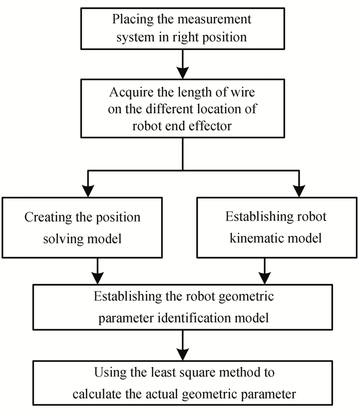
Fig. 4 is the robot geometric calibration scheme diagram.
|
Fig.4 Scheme of robot calibration algorithm |
2.1 Acquisition of Wire Length Data
First, the measurement system should be placed in a proper position before calibrating the robot, the wire should be connected to the measured point on the robot end effector, and the robot should not be interfered with by the wire. Then, the robot is moved to different location in the workspace, meanwhile the length of wire should be acquired when the robot is moving.
2.2 Calibration Algorithm of Industrial RobotTwo pieces of model should be established during the robot calibration:
(1) The position solving model of the measurement system.
The position and orientation parameters λ, β were used to establish the position solving model F(L, λ, β) according to the wire length of different positions L1, L2, ···, Ln in Section 1.3.
(2) Kinematic model of industrial robot.
D-H method is the classic way to establish robot kinematic model[22]. The joint coordinates were established by using four geometric parameters of the joint [θ d a α], and the four dimensions homogeneous transformation matrix was used to express the transformation relationship of the adjacent joint coordinates, which is shown in formula (10).
| $ \begin{aligned} { }_i^{\mathrm{i}-1} \boldsymbol{T} & =R\left(z, \theta_i\right) \operatorname{Trans}\left(0,0, d_i\right) \cdot \\ & \operatorname{Trans}\left(a_i, 0,0\right) R\left(x, \alpha_i\right)= \\ & {\left[\begin{array}{cccc} \mathrm{c} \theta_i & -\mathrm{s} \theta_i \mathrm{c} \alpha_i & \mathrm{s} \theta_i \mathrm{s} \alpha_i & a_i \mathrm{c} \theta \\ \mathrm{s} \theta_i & \mathrm{c} \theta_i \mathrm{c} \alpha_i & -\mathrm{c} \theta_i \mathrm{s} \alpha_i & a_i \mathrm{s} \theta \\ 0 & \mathrm{~s} \alpha_i & \mathrm{c} \alpha_i & d_i \\ 0 & 0 & 0 & 1 \end{array}\right] } \end{aligned} $ | (10) |
where, i=1, 2, ···, k and k is the number of robot joint, θi is the rotation angel around axis zi-1, di is the transformation distance along axis zi-1, ai is the transformation distance along axis xi, and αi is the rotation angel around axis xi.
The unknown robot geometric parameter was expressed by the vector
| $ \overrightarrow{\boldsymbol{X}}=\left[\theta_1, d_1, a_1, \alpha_1 \cdots \theta_k, d_k, a_k, \alpha_k\right] $ |
The homogeneous transformation matrix from the base coordinates to the end effector coordinates, if every adjacent joints are transformed in this manner, starting from the base coordination.
| $ { }_k^0 \boldsymbol{T}={ }_1^0 \boldsymbol{T}_2^1 \boldsymbol{T}_3^2 \boldsymbol{T} \cdots{ }_k^{\mathrm{k}-1} \boldsymbol{T} $ | (11) |
Matrix
| $ { }_k^0 \boldsymbol{T}=\left[\begin{array}{cccc} n_x & o_x & a_x & p_x \\ n_y & o_y & a_y & p_y \\ n_z & o_z & a_z & p_z \\ 0 & 0 & 0 & 1 \end{array}\right] $ | (12) |
where, the first three rows and first three columns of the matrix
| $ \begin{gathered} \boldsymbol{G}\left(\theta_1, d_1, a_1, \alpha_1 \cdots \theta_k, d_k, a_k, \alpha_k\right)= \\ {\left[\begin{array}{llll} p_x & p_y & p_z & 1 \end{array}\right]^{\mathrm{T}}} \end{gathered} $ | (13) |
(3) Identification method of robot geometric parameters.
The robot geometric parameter identification equation group can be achieved by simultaneous Eqs. (7) and (13). As shown in formula (14).
| $ \begin{aligned} & \boldsymbol{T}_A^R \boldsymbol{F}(L, \lambda, \beta)=\boldsymbol{G}\left(\theta_1, d_1, a_1, \alpha_1, \cdots,\right. \\ & \left.\quad \theta_k, d_k, a_k, \alpha_k\right) \end{aligned} $ | (14) |
A simulation program was developed in the following section, the orientation of robot base coordinates and measurement system coordinates is the same, and the direction of robot geometric parameter d1 is the same as dz. According to formula (6), there are three unknown parameters, such as B, dx, dy. The number of robot joints is supposed to be six, and each joint has four geometric parameters, thus, there are 24 unknown robot geometric parameters to identify. So, the number of measured points should be no less than 27, according to formula (7). The robot geometric parameters can be calculated by utilizing formula (9).
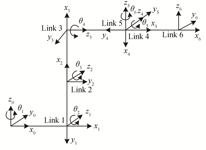
2.3 Simulation of Robot Calibration AlgorithmIn this section, ER type of robot was used to invalidate the robot calibration algorithm, which was produced by ESTUN Company. Fig. 5 shows the robot coordinates, which are established by the D-H model. The geometric parameters change to θ2, β2, a2, α2, since the second joint is parallel with the third joint, according to the MDH model. Table 1 shows the geometric parameters of all the robot joints, where θ1, θ2, ···, θ6 represent the initial value of all the robot rotation joints.
|
Fig.5 D-H model of ER robot |
| Table 1 Robot geometric parameter |
In the simulation program, all the actual robot geometric parameters are shown in Table 2.
| Table 2 Actual value of robot geometric parameter |
Simulation program was conducted according to the robot geometric parameter calibration scheme, as shown in Fig. 4. The simulation results can be seen in Fig. 6.

|
Fig.6 Influence of the number of calibration points on identification results |
It can be concluded from Fig. 6 that the transformation singularity between robot base coordinates and measurement system coordinates will emerge when the number of measured points fullfills to meet the identification requirement. So, in this paper, a kind of oversampling method was introduced to avoid this problem and improve the accuracy of parameter identification. The accuracy of robot geometric identification can achieve the level of 3e-10 after one time of iterative computation when the number of measured points is 40, and the results are shown in Table 3.
| Table 3 Relationship between actual value and algorithm value |
According to the simulation program, the maximum error of the joint length is only 3e-10 mm, and the maximum robot geometric parameter of angel is only 2e-10°. So, the accuracy and effectiveness of robot calibration algorithm were improved since the identification result is very close to the actual parameters.
3 Accuracy Analyze of Calibration AlgorithmIn the actual calibration process, the acquired data will be affected by many kinds of factors, and affect the identification result of robot geometric parameters finally. The immunity of several kinds of errors to the calibration algorithm is studied in this section, such as the measurement error of draw-wire encoder and rotation error of robot driving axis.
Fig. 7 is the process diagram of the influence on the robot calibration by errors.

|
Fig.7 Process diagram of the influence to robot calibration by errors |
(1) Imposed on the basis of the robot joint angle initial value θ1, ···, θk of random error, to acquire the actual length of wire.
(2) Applying the random error on the length of wire.
(3) Repeat the two previous steps to acquire the 40-number length of wire in different positions.
(4) Bring the acquired length of wire into the position solving model in Fig. 4, and establishing the robot geometric parameter identification model.
The least square method was used to compute the actual robot geometric parameter.
3.1 Error of Draw-wire Encoder MeasurementAccording to Fig. 7, the range of random error in Step 2 is ±0.001 mm, ±0.005 mm, ±0.01 mm, ±0.02 mm, ±0.03 mm respectively. Table 4 shows the relationship between the theoretical value of the wire length and the actual value of the wire length.
| Table 4 Relationship between actual value of wire length and theoretical value |
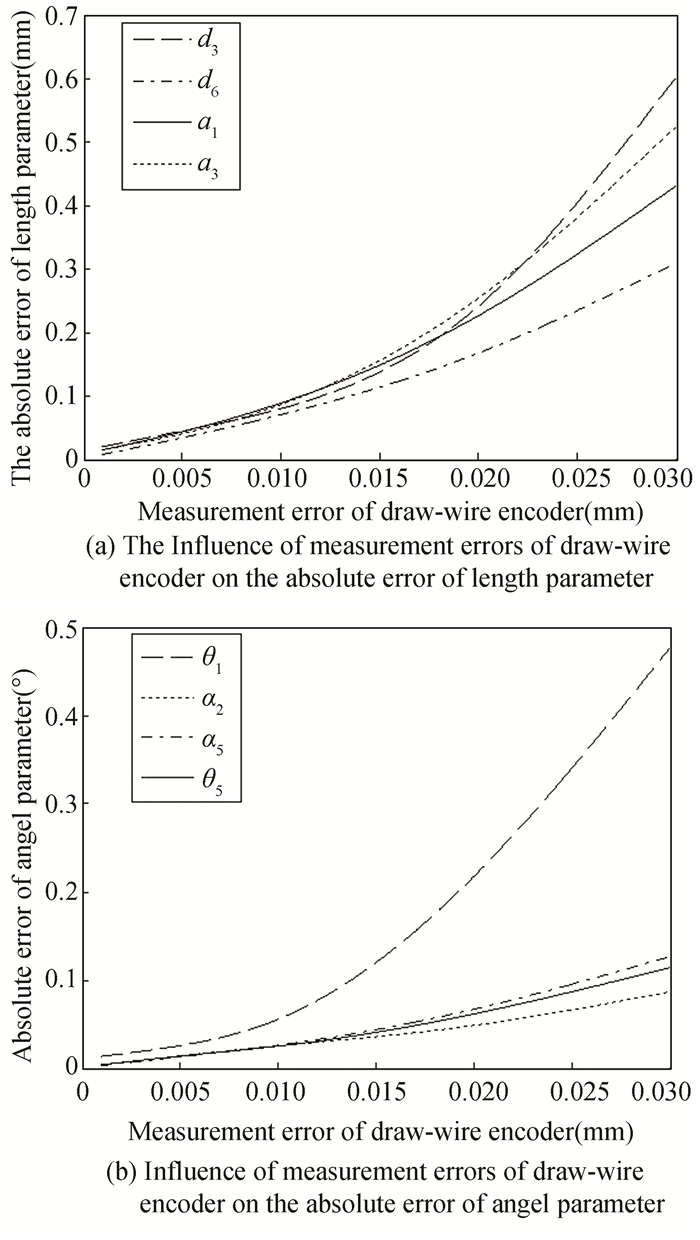
Comparing the theoretical value in Table 3 and the algorithm value according to the imposed length error of the wire, the result shows that the identification accuracies of length parameters θ1, α2, a5, θ5 and angle parameters d3, d6, a1, a3 was most affected by the wire length. The identification results were fitted into smooth curve as shown in Fig. 8.
|
Fig.8 Influence of measurement error on identification results |
According to Fig. 8, it can be concluded that: firstly, the robot geometric parameter identification accuracy is affected obviously when the draw-wire measurement error is more than 0.01 mm. Secondly, the maximum identification error of angle parameter among robot geometric parameters is only 0.047°, when the maximum error of draw-wire measurement is less than 0.01 mm, and the maximum identification error of length parameter among robot geometric parameters is only 0.089 mm. It provides a reference for draw-wire encoder selection, and the measurement error of draw-wire encode in this is less than 0.005 mm, which meets the identification accuracy.
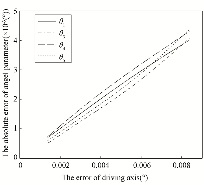
3.2 Analyze on Calibration Algorithm Immunity to Driving Axis ErrorAccording to Fig. 7, the range of random error of driving axis error in Step 1 is ±0.008°, ±0.006°, ±0.003°, ±0.001° respectively. Comparing the theoretical value in Table 3 and the algorithm value according to the imposed angle error of robot driving axis, the result shows that: the identification accuracy of length parameter has nothing to do with the driving axis error, and parameters θ1, θ3, θ4, θ5 among robot initial rotation angles θ1, ···, θ6 are most affected. The identification results were fitted into smooth curve as shown in Fig. 9.
|
Fig.9 Influence of driving axis error on identification results |
As shown in Fig. 9, it can be concluded that: firstly, the identification accuracy of length parameter has nothing to do with the driving axis error. Secondly, the effects of robot driving axis rotation error on robot angel parameter are linear, and the maximum error is only 0.0045° when the error of robot driving axis is less than 0.008°. So, the calibration algorithm has strong immunity to driving axis error.
3.3 Influence on Robot Calibration Algorithm Accuracy by Number of Calibration PointThe measurement error of draw-wire encoder and error of driving axis are difficult to avoid during the actual process of robot geometric parameter calibration. The accuracy of the robot geometric parameter identification can be affected by these factors, over-sampling method is presented in this paper which increases the identification redundancy of formula (9) by increasing the number of calibration points.
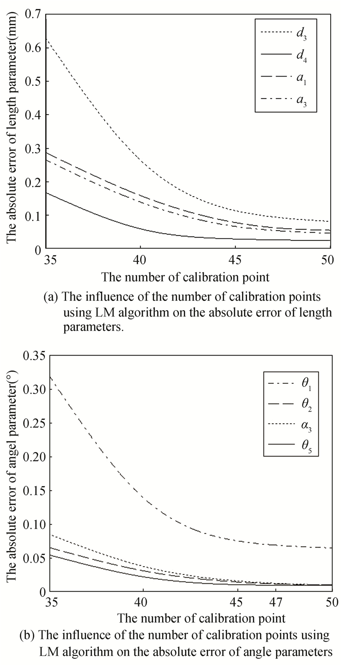
The measurement error of draw-wire encoder is supposed to be 0.01 mm, the error of robot driving axis is supposed to be 0.009°, and the deviation between axis X in measurement system coordinates and axis Z in robot base coordinates is supposed to be 0.1°, and the position deviation of axis z is supposed to be 0.1 mm. According to Fig. 7, these errors were applied to acquire the actual measurement data, and the position of robot end effector was moved to different locations with the number of positions being 35, 40, 45, 47, and 50 respectively. L-M method was used in MATLAB to acquire the identification result by iterating the initial value of robot geometric parameter.
Comparing the theoretical value in Table 3 and the algorithm value according to the method of over-sampling, the result shows that: the identification accuracies of length parameters among robot geometric parameters are d3, d4, α1, a3, and the angel parameters among robot geometric parameters are θ1, θ2, α3, θ5. Identification results were fitted into smooth curve as shown in Fig. 10.
|
Fig.10 Influence of number of calibration points on identification results |
As shown in Fig. 10, it can be concluded that: firstly, identification accuracy of robot geometric parameters improved significantly by using the method of over-sampling.
Secondly, the maximum error of robot length parameter is only 0.09 mm, and the maximum error of robot angle parameter is only 0.07°, and the accuracy improvement is not obvious when increasing the number of calibration numbers. So, taking into account factors such as the calibration time, the optimal number of calibration points is 47.
4 Robot Calibration ExperimentThe experiment facility is shown in Fig. 11. The type of ER30 robot manufactured by ESTUN was used as experimental subject, shown in the left of Fig. 11; the measurement system was located in the right of Fig. 11. The communication between draw-wire encoder and PC was performed based on MFC code, which meets the command of consecutive measurement during the process of experiment. The working temperature remain 20-23 ℃ unchanged, and the robot end effector is zero-load during the experiment was carried out.

|
Fig.11 Experiment facility |
Table 5 shows the nominal value of robot geometric parameter.
| Table 5 Robot geometric parameters |
Firstly, 47 calibration points were selected in the working range of robot (1200 mm×1200 mm×1200 mm), tutorials such as PTP code were used to teach the 47 discrete calibration points.
Secondly, place the wire in the zero position, and connect the wire to the robot end effector after the draw-wire encoder was powered, 47 number of wire length was acquired.
Finally, L-M method was used to identify the robot geometric parameter according to Section 2.2, and the result was converged after no more than 22 times of iteration, the result as shown in Table 6.
In this paper, DH model is used to model the kinematics of the robot. The principle of this model is to establish a joint coordinate system for each joint of the robot with 4 structural parameters [θ d a α], the transformation relationship between the coordinate systems of adjacent joints of the robot is expressed in the form of a homogeneous transformation matrix. The position and pose information of the robot end under the robot base coordinates is determined by connecting the adjacent joint coordinate systems. Therefore, the calibrated geometric parameters of the robot (as shown in Table 3 in Section 2.3) and the actual geometric parameters of the robot (see Table 2 in Section 2.3) are brought into the DH model, it can be calculated that the absolute positioning accuracy of the end of the industrial robot is 0.87 mm.
Error compensation was carried out by replacing the initial values with the algorithm values in Table 6, and the robot's absolute error was reduced from 4.32 mm to 0.87 mm after calibration, the absolute accuracy of robot was improved effectively.
| Table 6 Algorithm value of robot geometric parameters |
5 Conclusions
1) A kind of robot geometric parameter calibration algorithm was established based on measurement system containing position and orientation parameter. Robot geometric parameter identification model was established based on position solving model in measurement system and robot kinematic model, the least square method was used to compute the actual robot geometric parameter. Simulation examples were conducted that the accuracy of robot length parameter among geometric parameters be improved to 3e-8 μm, and the accuracy of robot angel parameter among geometric parameters be improved to 7.2e-7″. Thus, the effectiveness and accuracy of robot calibration algorithm were improved.
2) The influence of draw-wire encoder measurement error and robot driving axis error on the accuracy of calibration algorithm was analyzed, and simulation examples were carried out to verify the immunity of calibration algorithm to robot driving axis error, and the calibration accuracy can be insured in the case of the measurement error of draw-wire encoder is less than 0.01 mm.
3) Over-sampling method was used to improve the identification accuracy of calibration algorithm, and experiment was developed by use of ER type robot. The experimental results showed that the absolute accuracy of robot decreased from 4.32 mm to 0.87 mm after calibration, which improved the robot's absolute accuracy effectively.
4) The robot geometric parameter calibration method has the following advantages: easy to operate and effectuate, high environmental compatibility and accuracy, and the method is particularly versatile that the calibration algorithm can not only be used in ordinary robot but also can calibrate parallel mechanisms or other complex mechanical device.
| [1] |
Johnson M, Liu R, Gopalan N, et al. An approach to human-robot collaborative drilling and fastening in aerospace final assembly. AIAA Scitech 2021 Forum, 2021, 10(23): 270-286. DOI:10.2514/6.2021-0270 (  0) 0) |
| [2] |
Dibari P, Nitti M, Patruno C, et al. An accurate hardware calibration and 3D point cloud stitching towards automatic quality control in aerospace manufacturing. Proceedings of the 9th IEEE International Workshop on Metrology for Aerospace, 2022, 12(3): 265-269. DOI:10.1109/MetroAeroSpace54187.2022.9856030 (  0) 0) |
| [3] |
Ren Yongjie, Zhu Jigui, Yang Xueyou, et al. Method of robot calibration based on laser tracker. Chinese Journal of Mechanical Engineering, 2007, 43(9): 195-200. DOI:10.3901/JME.2007.09.195 (  0) 0) |
| [4] |
Sheng Jianxin, Tian Wei. Aircraft flexible assembly technology based on industrial robots. Journal of Nanjing University of Aeronautics & Astronautics, 2014, 46(2): 181-189. (  0) 0) |
| [5] |
Zhang Xu, Zheng Zelong, Qi Yong, et al. Parameter identification and calibration of D-H model for 6-DOF serial robots. Robot, 2016, 38(3): 360-370. DOI:10.13973/j.cnki.robot.2016.0360 (  0) 0) |
| [6] |
Du G, Zhang P. Online robot calibration based on vision measurement. Robotics and Computer-Intergrated Manufacturing, 2013, 29(6): 484-492. DOI:10.1016/j.rcim.2013.05.003 (  0) 0) |
| [7] |
Santolaria J, Conte J, Ginés M. Laser tracker-based kinematic parameter calibration of industrial robots by improved CPA method and active retroreflector. The International Journal of Advanced Manufacturing Technology, 2013, 66(12): 2087-2106. DOI:10.1007/s00170-012-4484-6 (  0) 0) |
| [8] |
Chen Gang, Li Tong, Chu Ming, et al. Review on kinematics calibration technology of serial robots. International Journal of Precision Engineering and Manufacturing, 2014, 15(8): 1759-1774. DOI:10.1007/s12541-014-0528-1 (  0) 0) |
| [9] |
Fraczek J, Busko Z. Calibration of multi-robot system without and under load using electronic theodolites. Proceedings of the First Workshop on Robot Motion and Control. RoMoCo'99 (Cat. No. 99EX353), Kiekrz, Poland. 1999.71-75, DOI: 10.1109/ROMOCO.1999.791055.
(  0) 0) |
| [10] |
Chen J, Chao L. Positioning error analysis for robot manipulators with all rotary joints. IEEE Journal of Robotics and Automation, 1987, 3(6): 539-545. DOI:10.1109/ROBOT.1986.1087544 (  0) 0) |
| [11] |
WU Defeng. Novel approach to calibration main body of a three-dimensional scanning robotic system. Journal of Mechanical Engineering, 2011, 47(17): 9-14. DOI:10.3901/JME.2011.17.009 (  0) 0) |
| [12] |
Albert Nubiola, Ilian A. Bonev. Absolute calibration of an ABB IRB 1600 robot using a laser tracker. Robotics and Computer-Integrated Manufacturing, 2013, 29(1): 236-245. DOI:10.1016/j.rcim.2012.06.004 (  0) 0) |
| [13] |
Newman W S, Birkhimer C E, Horning R J, et al. Calibration of a Motoman P8 robot based on laser tracking. Proceedings of the 2000 ICRA. Millennium Conference. IEEE International Conference on Robotics and Automation. Symposia Proceedings (Cat. No. 00CH37065), San Francisco, CA, 2000, 4: 3597-3602. DOI: 10.1109/ROBOT.2000.845292.
(  0) 0) |
| [14] |
Wang Yi. Compensation for position error of industrial coordinate measurement robot. Journal of Mechanical Engineering, 2011, 47(15): 31-36. DOI:10.3901/JME.2011.15.031 (  0) 0) |
| [15] |
Gong Cheng. Design and Development of Dynamic Spatial Position Measurement System. Nanjing: Nanjing University of Aeronautics and Astronautics, 2014.
(  0) 0) |
| [16] |
Li Wenyi, Dong Zhong, Tong Shang, et al. Error detection of series-parallel palletizing robot based on encoders. Machinery and Electronics, 2013(12): 52-55. (  0) 0) |
| [17] |
Cheng Shiliang. Design of the Calibration System Based on draw-wire Sensors for Industrial Robot. Harbin: Harbin Institute of Technology, 2014.
(  0) 0) |
| [18] |
Zhang Deli, Wang Min. A Calibration Method of Industrial Robot Based on Cable Encoder. Journal of Mechanical Engineering, 2015(9): 62-78. (  0) 0) |
| [19] |
Hong Weisong. Research on Calibration and Measurement's System for Industrial Robot Based on Cable Actuated Position Encoder. Nanjing: Nanjing University of Aeronautics and Astronautics, 2016.
(  0) 0) |
| [20] |
Niu Xuejuan, Liu Jingtai. Robot tool coordinate system calibration based on singular value decomposition. Automation and Instrumentation, 2008, 23(3): 1-4. (  0) 0) |
| [21] |
Wu Liao, Yang Xiangdong, Lan Shanqing. Robot TCF calibration based on planar template. Robot, 2021, 34(1): 98-103. DOI:10.3724/SP.J.1218.2012.00098 (  0) 0) |
| [22] |
Denavit J, Hartenberg R S. A kinematic notation for lower-pair mechanisms based on matrices. Journal of Applied Mechanics, 2015, 25(6): 215-221. DOI:10.1115/1.4011045 (  0) 0) |
 2023, Vol. 30


