2. Tianjin 707 HI-TECH CO.,LTD,Tianjin 300409, China
At present, there is still a large proportion of manual spot welding equipment used in the trial production workshops of white body and in the resistance welding of nuts and screws in a large number of component factories. Especially in the application scenarios where one equipment is used to weld multiple workpieces (one machine with multiple parts) in component factories, different workpieces often require different welding specification parameters[1]. The traditional specification selection needs to check the process manually, determine the specification number corresponding to the welding process parameters according to the type of the weldment, and then select the corresponding specification number through the Dip switch on the spot welding equipment[2-3]. Due to the manual selection, especially the existence of a large number of symmetrical parts and nuts and screws with similar models, this traditional method is prone to wrong selection of specifications, and the dip switch is accidentally touched in the middle, resulting in welding quality problems of the workpiece. With the development of information technology and electronic technology, many scholars and companies have proposed their own solutions. For example, the Wang Kehong team[4] from Nanjing University of Technology has developed a set of QR code scanning and welding process specification parameter automatic issuance system based on SQL Server and LabVIEW for arc welding, which has achieved automatic calling of welding card process specification parameters and automatic issuance of current and voltage parameters, However, the above methods are widely used in arc welding and are not suitable for resistance welding; FAW sedan achieved automatic selection of specifications for body suspension welding machine by introducing a detection switch, but did not solve the problem of automatic selection of welding specifications for nuts and screws in seat spot welding[5]; Tianjin 707 HI-TECH Co., Ltd. introduced a centralized specification selection system for the easy accidental touch of the welding clamp handle specification of the suspension welding machine[6], but only solved the problem of the accidental touch of two sets of standard Dip switch of the welding clamp handle.
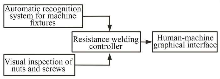
This article proposes a fully automatic specification selection system for resistance welding equipment, which realizes the recognition of different base metal workpieces through the automatic recognition system of machine fixtures. By introducing a visual inspection system for nuts and screws, the recognition of workpieces is achieved. The correctness of the call specification is further ensured through secondary graphical confirmation. This system has achieved reliable and fully automatic standard selection of resistance welding equipment, and has achieved significant results in practical applications, effectively improving the welding quality of batch workpieces. Fig. 1 is the system diagram.
|
Fig.1 System block diagram |
1 System Design
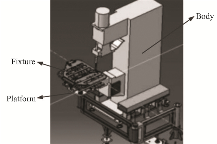
Spot welding equipment usually includes the body, welding transformer, controller, platform, fixture, etc. (as shown in Fig. 2). The base metal workpiece of the welding workpiece is installed on the fixture, fixed and positioned through the fixture, and the fixture is fixed on the body platform. The welding transformer and controller are installed in the body[7-8].
|
Fig.2 Seat spot welding system |
The resistance welding controller of this system is connected to the machine fixture recognition system, camera, HMI(Human Machine Interface), etc. through external interfaces. Fig. 3 depicts the system architecture. The camera is used to identify nuts and screws, and the resistance welding controller compares and matches the welding specification number corresponding to the workpiece one by one based on the machine fixture recognition system signal and the nut and screw shape with the data stored in the database to achieve automatic calling. HMI is used for graphical display of base metal plates and nuts and screws, facilitating secondary confirmation by workers.

|
Fig.3 System Interface block diagram |
2 Automatic Recognition System for Machine Fixtures
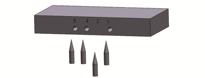
In the spot welding system, each type of motherboard workpiece usually requires a separate fixture due to its different appearance[9].Therefore, the denominator plate can be distinguished by identifying the fixture model. This system has added an automatic recognition mechanism for machine fixtures, which pre numbers the machine fixtures and prefabricates conical holes at specific positions on the machine fixtures according to the numbers, as shown in Figs. 4 and 5. By utilizing four conical holes, 16 different machine fixtures can be distinguished. The numbered detection cones are added on the machine and connected to the relevant relays before being integrated into the IO detection interface circuit of the controller. This allows for precise identification and control of the machine fixtures during operation, ensuring seamless processing of various workpiece types without requiring manual adjustments.

|
Fig.4 Schematic diagram of automatic recognition mechanism for machine fixtures |
|
Fig.5 Schematic diagram of automatic recognition mechanism for machine fixture with number 13 |
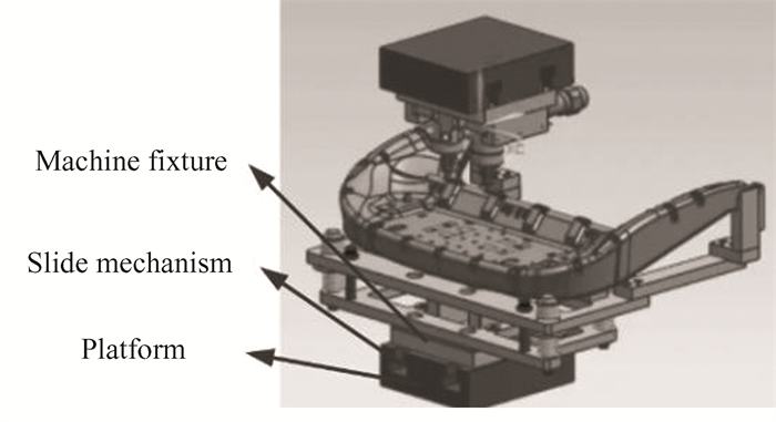
By incorporating sliding mechanisms on both the machine and fixtures, the position of the pre-set conical holes for each fixture's code can be accurately aligned with the numbered detection cones on the machine, as depicted in Fig. 6. This ensures proper alignment between the fixtures and the machine during operation. Moreover, automatic recognition of workpieces made of different materials is achieved through the machine fixture's automatic recognition system. This allows for seamless identification and processing of various workpiece types without requiring manual adjustments.
|
Fig.6 Schematic diagram of slide rail mechanism |
3 Visual Inspection System
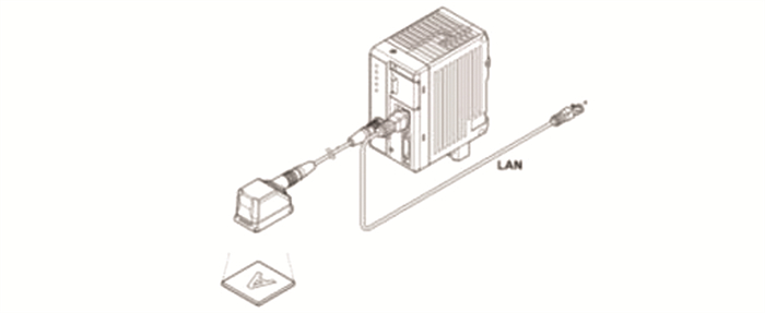
In spot welding, there is a scenario where the same base metal workpiece is welded with multiple nuts and screws of different models and specifications[10-11].Therefore, in addition to identifying different base metal workpieces, it is also necessary to identify different nuts and screws. The system adopts an industrial camera sensor head from Keinz and a supporting camera dedicated controller. The sensor head and dedicated controller are connected through control cables, and the welding controller and camera dedicated controller are connected through LAN(Local Area Network) cables. As shown in Fig. 7.
|
Fig.7 Connection diagram of visual inspection system |
The sensing head adopts a 1/3 inch CMOS(Complementary Metal Oxide Semiconductor) image receiving element, reaching 752×480 pixels. The field of view can reach 200 mm (height)×150 mm (vertical) when installed at a distance of 500 mm. It can achieve automatic focusing and has a white LED(Light Emitting Diode) supplementary light source.
The camera dedicated controller is equipped with an external proximity switch, which initiates detection when there are nuts and screws. The welding controller compares the detection results with the nut and screw models saved in the database one by one, and finally analyzes the welded base material and screw types based on the base material workpiece number recognized by the machine fixture, and automatically selects the corresponding welding specifications. Fig. 8 shows the visual inspection effect of the nut. The system prompts whether the corresponding nut model has been matched in the database through different colors in the HMI human-machine interaction system.

|
Fig.8 Visual inspection rendering |
4 Software Design
The system software adopts the design method of SASD(Structured Analysis Structured Design), uses the structured analysis method to analyze the requirements, and uses the structured programming method to design the software into a structure composed of relatively independent and single functional modules. Following the design principles of high cohesion and low coupling[12-13], software structure design, data design, interface design, and process design were completed. A human-machine interaction interface has been implemented on the HMI, which allows for pre input of information such as base material workpiece and nut screw images into the system database for graphical display in secondary confirmation.
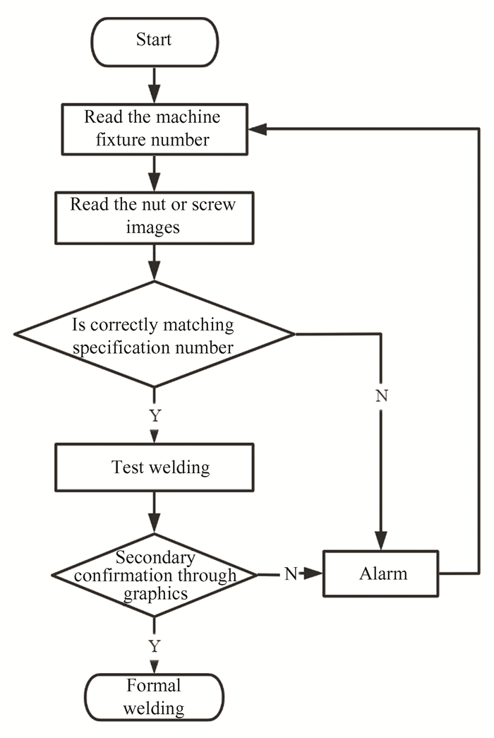
After the system starts running, obtain the machine fixture number and nut screw model separately, and compare them one by one in the database to match the corresponding specification number. When the matching fails, an alarm will be triggered in the HMI human-machine interaction. When the matching is successful, the corresponding specification number will be automatically selected. After the worker conducts the trial welding, they need to compare the graphic display images with the actual working conditions in the HMI human-machine interaction system, and perform secondary confirmation in the system. In subsequent welding, spot welding will be carried out according to the automatically selected specification for process output. Once there is a change in the machine fixture number or nut screw, a second confirmation is required.Fig. 9 displays the operational workflow of the system software.
|
Fig.9 Software flowchart |
5 Test
In automobile manufacturing, there are many body parts that require welding multiple nuts and bolts of different models on a single base material. Additionally, there are many symmetrical parts that require accurate welding. However, the manual process of searching for welding specifications based on process drawings and selecting them through coding can easily lead to confusion, resulting in specification calling errors and quality problems with the final product. To address this issue, a certain automobile factory's welding workshop implemented an automated system for welding specifications in spot welding equipment. This system has ensured the full automation of welding specifications and further ensured the correctness of specification calling through secondary verification.
To evaluate the effectiveness of this system, the number of quality problems per hundred workpieces before and after the application of this system was compared for two months each for the two most error-prone application scenarios. The statistics showed that the quality problem rate was high at 10% before the application of the system for the first workpiece in Table 1, which had multiple hole positions and two different types of nuts. However, after the implementation of the system, the quality problem rate decreased to 0, indicating that the system successfully solved the welding quality problem caused by specification calling errors.
| Table 1 Non-symmetrical component quality issue statistics table |
Table 2 compares the number of quality issues per hundred pieces of three types of symmetrical components during this period. Before the application of this system, there were an average of 7 quality issues per hundred pieces. However, after two months of using the system, no such issues were found again, indicating significant improvement in the quality of welding.
| Table 2 Symmetric component quality problem statistics table |
6 Conclusions
In conclusion, the results of this research suggest that the proposed approach is a promising solution for addressing the research question and achieving the research objectives. The experimental results show that the proposed method outperforms existing methods in terms of accuracy, efficiency, and robustness, indicating its potential for practical applications. However, further validation and optimization are necessary to ensure the generalizability and scalability of the proposed method across different scenarios and datasets. This study contributes to the literature by providing new insights and perspectives on the topic and advancing the state-of-the-art in the field. Future research can build upon these findings and investigate new directions and challenges.
| [1] |
Guo R P, Yang Z L, Li Y. Application and development status of resistance welding in industrial production. Welding Digest of Machinery Manufacturing, 2015, 255(1): 35-38. (  0) 0) |
| [2] |
Zhang S B, Liu J, Liu A J, et al. Design and optimization of welding parameters for fixed spot welder nut spot welding. Internal Combustion Engine & Parts, 2017, 240(12): 62-63. (  0) 0) |
| [3] |
Ji L Q, Wu G. Wheel multi head automatic welding device. Modern Manufacturing Engineering, 2003(3): 82-83. (  0) 0) |
| [4] |
Yang Z H. Welding Seam Recognition and Parameter Automatic Issuance Technology in Digital Assembly and Welding Workshop. Nanjing: Nanjing University of Science and Technology, 2017.
(  0) 0) |
| [5] |
Han S L, Sun G L, Zhang H R, et al. A method and device for automatically calling the welding specifications of manual suspension spot welding machines. China: CN110153542A, 2019-08-23.
(  0) 0) |
| [6] |
Yin G, Gao Z L, Liu Z H, et al. Welding centralized specification selection system. China: CN208399950U, 2019-01-18.
(  0) 0) |
| [7] |
Li W. Development and Performance Evaluation of Pressure Resistance Welding Machine. Changsha: Hunan University, 2018.
(  0) 0) |
| [8] |
Jiao H L. Optimization and Quality Evaluation of Resistance Projection Welding Process for Ultra High Strength Hot Formed Steel. Shanghai: Shanghai Jiao Tong University, 2014.
(  0) 0) |
| [9] |
Yuan Z T. Research on resistance welding fixture. Automobile Technology & Material, 1988(4): 26-30. (  0) 0) |
| [10] |
Lai B W. The application of welding nuts in the automotive industry. Welding Technology, 1992(1): 22-24. (  0) 0) |
| [11] |
Zhang L. Projection welding process for square nuts based on computer simulation technology. Electric Welding Machine, 2014, 44(11): 185-190. (  0) 0) |
| [12] |
Li X D, Yu G. Preface to the special journal on embedded system software design methods and technologies. Journal of Software, 2014, 25(2): 177-178. (  0) 0) |
| [13] |
He S M, Yang H, Wang H B, et al. Review and prospect of digital design of electric vehicle power control unit software. Transactions of China Electrotechnical Society, 2021, 36(24): 5101-5114. (  0) 0) |
 2024, Vol. 31


