Compared with centralized driving system of traditional motors, the in-wheel motor drive has shorter transmission chain, higher efficiency, better dynamic performance and more flexible control[1]. Therefore, the driving mode of the wheeled mobile robot mostly adopts the distributed drive scheme of in-wheel motor. The permanent magnet synchronous motor (PMSM) structure is used in the in-wheel motor. Due to the large amount of heat generated by the high-speed movement of the motor, the temperature of the permanent magnet increases[2]. The permanent magnet inside the motor will undergo irreversible demagnetization at a certain temperature, which will decrease the torque output performance of the motor[3]. With the accumulation of heat, the demagnetization amount gradually increases, then the magnetic induction intensity generated by the permanent magnet decreases, and the flux linkage parameters in the motor will also decrease[4]. The high-performance control technology of PMSM mainly includes field orientation control (FOC) and direct torque control (DTC)[5].
Aiming at reducing the torque ripple of PMSM control system, many scholars have researched current compensation methods. Based on the establishment of the back-EMF offset model, Ref. [6] proposed a current compensation method to improve the dynamic tracking performance of the torque. Ref. [7] built a nonlinear feedforward compensation method to suppress torque ripple through harmonic current components. Ref. [8] used the dynamic nonlinear mathematical model of PMSM to establish a current feedforward compensation control system, which can effectively reduce the torque ripple. Ref. [9] compensated the friction torque based on the speed controller and the current controller to improve the operating performance of the motor. By adding harmonic current and harmonic voltage feedforward compensation to the traditional vector control system, Ref. [10] achieved effective suppression of motor torque ripple. Ref. [11] proposed a current loop delay compensation strategy for permanent magnet synchronous motors based on closed-loop current prediction. The loop delay effect is suppressed by adding closed-loop current prediction delay feedforward compensation to the traditional complex vector current regulator. This kind of research compensates the external interference from the perspective of current compensation, which effectively improves the stability of the motor output torque in the face of external interference. However, the real-time performance of the control system is poor in absence of lacking real-time monitoring and estimation of the global error of the system.
The control method that utilizes an observer to analyse the system disturbance and combines with current compensation has become the main method to suppress the influence of external disturbance on PMSM control system and compensate the system disturbance in real time. In Ref. [12], the current feedforward model with sliding mode observer was introduced into the traditional deadbeat current prediction model, which reduces the current jitter and eliminates the steady-state error. Ref. [13] used the adaptive disturbance observer to accurately estimate the torque ripple of the stator motor and perform adaptive feedforward compensation, which effectively improves the speed control accuracy. Ref. [14] combined the disturbance observer with the speed controller to effectively improve the control accuracy and response speed of the system. Based on the establishment of parameter adaptive disturbance observer, Ref. [15] proposed a speed controller based on disturbance observer, which realized the stable adjustment of rotor speed. Ref. [16] built a position observer based on motor dynamics, combined with current control to achieve rapid convergence of parameter uncertainty disturbances.
The popular control strategies for the inherent parameters of the motor do not consider the influence of permanent magnet demagnetization and the disturbance of demagnetization on system parameters. Therefore, the influence of demagnetization in FOC is first quantified in this paper. According to the mathematical model of PMSM[17], the change of demagnetization magnetic induction intensity is characterized as the change of flux linkage parameters. A current component feedforward compensation method is proposed to compensate the disturbance caused by the change of flux linkage parameters. Furthermore, the extended state observer (ESO) is used to estimate the global disturbance of the control system, and the current feedforward is used to accurately compensate the system disturbance to suppress the demagnetization interference effectively.
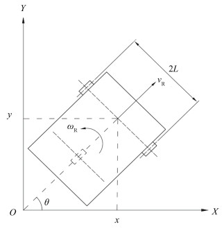
1 Kinematics Model of Differential DrivingThe driving system of the mobile robot studied in this work is composed of a set of differential wheels and a universal wheel. The differential wheel uses a hub motor to provide the linear speed and angular velocity. As shown in Fig. 1, the simplified model is given for kinematics modeling and analysis, the inertial coordinate system is set to OXY, which is a fixed coordinate system in the coordinate plane.
|
Fig.1 The motion model of wheeled robot |
There are five pose variables to describe robot moving, which are the displacement x in the X direction, the displacement y in the Y direction, the pose angle θ of the robot, the angular displacement αl of the left wheel and the angular displacement αr of the right wheel. The pose of the wheeled mobile robot can be written as:
| $ {\boldsymbol{q}}_{\mathrm{R}}=\left[x, y, \theta, \alpha_{\rm{l}}, \alpha_{\mathrm{r}}\right]^{\mathrm{T}} $ | (1) |
Redefining the pose of wheeled robots as qR=[x, y, θ]T. In the trajectory tracking of mobile robots, it is often sufficient to know only the coordinates (x, y) of the robot pose q and pose angle θ, then the wheeled robot kinematics model [18] can be defined as:
| $ \left[\begin{array}{c} \dot{x} \\ \dot{y} \\ \dot{\theta} \end{array}\right]=\left[\begin{array}{cc} \cos \theta & 0 \\ \sin \theta & 0 \\ 0 & 1 \end{array}\right]\left[\begin{array}{c} v_{\mathrm{R}} \\ \omega_{\mathrm{R}} \end{array}\right] $ | (2) |
where vR and ωR denotes the linear velocity, angular velocity of the robot.
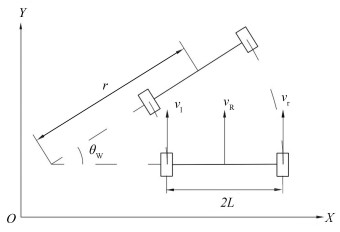
The front wheel adopts the hub motor, with the radius rw. The wheel track is 2L, as shown in Fig. 2. In this differential drive, the steering motion of the mobile robot is realized by controlling the wheel speed difference between two wheels. As shown in Fig. 2, if the linear velocity vr of the right wheel is greater than the linear velocity vl of the left wheel, the movement direction of the robot will shift to the left, because the displacement of the right wheel is greater than the displacement of the left wheel. The law of differential motion is represented as follows:
| $ v_{\mathrm{R}}=\frac{v_1+v_{\mathrm{r}}}{2} $ | (3) |
|
Fig.2 The motion model of differential driving |
The driving wheel adopts the hub motor, then, the motor speed is equal to the hub angular velocity and the linear speed can be directly converted to the motor speed. The relationship between the linear velocity v of the hub and the angular velocity ω of the motor can be written as:
| $ \left\{\begin{array}{l} v_{\mathrm{l}}=2 \pi \omega_{\mathrm{l}} r_{\mathrm{w}} \\ v_{\mathrm{r}}=2 \pi \omega_{\mathrm{r}} r_{\mathrm{w}} \end{array}\right. $ | (4) |
where ωl and ωr indicates the angular velocity of the left, right wheel motor.
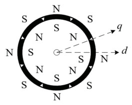
2 Demagnetization Error Compensation Control of PMSM 2.1 Demagnetization Mathematical Model of PMSMIn the permanent magnet fundamental excitation magnetic field of the PMSM(permanent magnet synchronous motor), as shown in Fig. 3, the d-axis coincides with the axis of the rotor magnetic pole, the q-axis is located at 1/2 of the two adjacent magnetic poles, and the q-axis is ahead of the d-axis by 90°. The electromagnetic torque equation in the d-q rotor coordinate [19] is written as follows:
| $ T_e=\frac{3}{2} p i_q\left[i_d\left(L_d-L_q\right)+\varPsi_f\right] $ | (5) |
|
Fig.3 Rotor structure of PMSM |
where id and iq are the d-axis and q-axis currents, respectively, Ld and Lq are the d-axis and q-axis inductances respectively, Ψf is the permanent magnet flux linkage, and p is the pole-pair.
The mechanical motion equation[20] is represented as follows:
| $ J \frac{{\mathrm{d}} \omega}{{\mathrm{d}} t}=T_{\rm{e}}-K \omega-T_{\mathrm{L}} $ | (6) |
where J is the moment of inertia, ω is the angular velocity of the motor, K is the viscous friction coefficient of the system, and TL is the load torque.
The mechanical motion Eq.(6) can be regarded as a differential equation of angular velocity ω with respect to time t. By solving the differential Eq.(6), the angular velocity ω of the motor can be finally obtained:
| $ \omega=\frac{T_{\mathrm{e}}-T_{\mathrm{L}}}{K}-\frac{1}{K} {\mathrm{e}}^{-\frac{K}{J}(t+m)} $ | (7) |
where m is a constant generated in the process of solving differential equations, and e is a natural constant.
The magnetic induction intensity is defined as B, and the relationship between the permanent magnet flux linkage and the magnetic induction intensity is written as follows:
| $ \varPsi_f=N B S \cos \theta_0 $ | (8) |
where N is the number of turns of the coil, S is the area perpendicular to the magnetic field line, and θ0 is the vertical angle between S and B.
In order to express the effect of demagnetization in system, the expression of demagnetization can be defined as:
| $ D_B=\frac{B_0^{\prime}}{B_0} $ | (9) |
where B0 is the magnetic induction intensity without demagnetization, and B′0 is the magnetic induction intensity under demagnetization.
Substituting Eq. (8) into Eq.(9), the demagnetized flux linkage can be obtained as follows:
| $ \varPsi_f^{\prime}=D_B \varPsi_f $ | (10) |
where Ψ′f denotes the demagnetized flux linkage.
By defining ΔL=Ld-Lq, Δt=t+m, and substituting Eq. (5), Eq. (8) into Eq. (7), the relationship between angular velocity and magnetic induction intensity can be obtained as follows:
| $ \omega=\frac{1}{K}\left[\frac{3}{2} p i_q\left(i_d \Delta L+N B S \cos \theta_0\right)-T_{\mathrm{L}}-{\mathrm{e}}^{-\frac{K}{J} \Delta t}\right] $ | (11) |
According to Eq.(11), if the permanent magnet demagnetizes, the magnetic induction intensity B decreases, and the angular velocity ω of the motor output will also decrease, then a stable speed tracking error occurs. It will eventually affect the speed tracking accuracy of the robot in this driving mode. In Eq. (11), the d-axis current and q-axis current are two variables that can be changed by the permanent magnet synchronous motor control system. Therefore, the speed loss caused by demagnetization can be compensated by current feedforward.
2.2 Current Feedforward Vector Control MethodThe mathematical model shows that the permanent magnet synchronous motor is a nonlinear control object, and there is a coupling between the d-axis current component id and the q-axis current component iq.
Assuming the PMSM has the same control performance as the DC motor and permanent magnet does not produce additional demagnetization, the linear decoupling control system adopt id=0, that means the stator current vector always occurs along the q-axis which is orthogonal to the rotor flux vector.
The control strategy in this study ensures that there is no armature reaction in d-axis when id=0, then the permanent magnet will not demagnetize except for the influence of temperature, and the PMSM in the static three-phase coordinate is completely decoupled. Furthermore, the stator inductance of PMSM could be deduce to Lq=Ld. By substituting Lq=Ld into Eq. (5), the electromagnetic torque equation under id=0 control can be obtained:
| $ T_e=1.5 p i_q \varPsi_f $ | (12) |
In Eq.(12), the electromagnetic torque generated by the motor is related to the q-axis current iq and the permanent magnet flux linkage Ψf. According to Eq.(8), the flux linkage Ψf is positively correlated with the magnetic induction intensity B. This paper converts the influence of permanent magnet demagnetization on the magnetic field into the influence on the flux linkage parameters. Then the impact of demagnetization on the system can be simulated, and this effect can be changed by the control current iq, the disturbance of system can be reduced by current feedforward compensation finally. The total disturbance to the whole control system after the demagnetization of the permanent magnet is defined as follows:
| $ E=E_1+E_2 $ | (13) |
where E1 is the effect of demagnetization on the electromagnetic torque, it can be compensated by increasing the q-axis current by Eq.(12). E2 is the uncertain influence of demagnetization on the parameters of vector control system.
E1 can be compensated by current feedforward method, E2 needs to be estimated in real time by disturbance observer and compensated by current feedforward control strategy. The velocity tracking error e1 caused by E1 is defined as follows:
| $ e_1=\omega_{\text {ref }}-\omega $ | (14) |
where ωref is the target speed without demagnetization in ideal state, then ωref is a fixed value when the target speed is given, and ω is the actual output speed of the motor.
By substituting Eq. (8) and Eq. (11) into Eq.(14), the following equation can be obtained:
| $ e_1=\frac{1}{K}\left[\frac{3}{2} p i_q\left(i_d \Delta L+\varPsi_f-\hat{\varPsi}_f\right)\right] $ | (15) |
where
When using id=0 control strategy, Eq. (15) can be represented as the following form:
| $ e_1=\frac{3}{2 K} p i_q\left(\varPsi_f-\hat{\varPsi}_f\right) $ | (16) |
Solving the derivative of the error e1 and substituting Eq. (6) into it, the derivative of e1 can be expressed as:
| $ \dot{e}_1=\dot{\omega}_{\text {ref }}-\dot{\omega}=\dot{\omega}_{\text {ref }}-\frac{1}{J}\left(T_{\mathrm{e}}-K \omega-T_{\mathrm{L}}\right) $ | (17) |
In the speed controller, the q-axis virtual current input is defined as:
| $ i_q=\frac{2}{3} p \hat{\varPsi}_f\left(J \dot{\omega}_{\text {ref }}-J c_1 \dot{e}_1+K \omega+T_{\mathrm{L}}\right) $ | (18) |
where c1 is the controller parameter.
2.3 ESO-based Vector Control SystemAiming at the unknown influence of permanent magnet irreversible demagnetization on PMSM control system, the state observer can be used to observe the uncertain disturbance real-timely in the control system. In the torque control system of demagnetized PMSM, the cause of parameter disturbance is a single interference source, and the disturbance model can be regarded as a first-order uncertain system. The first-order uncertain system [21] can be expressed as follows:
| $ \dot{x}=f(x, t)+e_2(t)+b u(t) $ | (19) |
where f(x, t) is an unknown nonlinear function, e2(t) is an uncertain parameter disturbance, u(t) is the control signal, x is the system output, b is the control gain.
Considering the concentrated disturbance a(t)=f(x, t)+e2(t) as an extended state, then Eq. (19) can be expressed as follows:
| $ \dot{x}=a(t)+b u(t) $ | (20) |
By defining x1=x, x2=a(t), system (20) can be extended to the following form:
| $ \left\{\begin{array}{l} \dot{x}_1=x_2+b u(t) \\ \dot{x}_2=c(t) \end{array}\right. $ | (21) |
where
| $ \left\{\begin{array}{l} \dot{z}_1=z_2-\beta_1\left(z_1-n\right)+b u \\ \dot{z}_2=-\beta_2\left(z_1-n\right) \end{array}\right. $ | (22) |
where -β1(β1>0) and -β2(β2>0) is the observer gain, z1 and z2 are the estimated values of x1 and e2, respectively.
When adopting id=0 vector control strategy, defining n=ω, u=iq. According to the mathematical model of PMSM, when id=0 is used for vector control, if the other parameters are constant, iq(t) is proportional to Te(t). Hence, in order to decrease the velocity error caused by demagnetization, when z1 < ω, bu>0, the torque is increased. When z1>ω, bu < 0, the torque is reduced to match the load torque.
The system block diagram of the current feedforward vector control method based on the extended state observer (ESO-FOC) is shown in Fig. 4, where v0 represents the given robot reference linear velocity, and the reference velocity ωref of the motor can be calculated by the differential motion law. The velocity closed-loop PI controller outputs are idref and iqref. Due to the id=0 in this control strategy, the actual input of the basic FOC is only the q-axis reference current. Based on the actual velocity of the motor and the actual current of the quadrature axis, ESO performs interference estimation and feedforward compensation on the quadrature axis control current.

|
Fig.4 The block diagram of vector control system based on ESO |
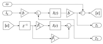
In order to enable the ESO to observe the system state in real time, it is necessary to use the q-axis current as the observer input. bu=biq=Te is defined, and the observer structure is built on the MATLAB/Simulink platform as follows:
Thereinto, z-1 is the delay module, which saves the input signal by one sampling period and output parameters to the FOC. I(z) is the PID controller module with integral link to adjust the static error generated by the input. b′ is the output gain to adjust the output disturbance caused by the PID integral link.
2.4 Stability AnalysisAccording to the ESO-based vector control system, the Lyapunov function of the closed-loop control system can be constructed as follows:
| $ V_x=\frac{1}{2} e_1^2+\frac{1}{2} e_2^2 $ | (23) |
where e1 and e2 are the speed tracking error caused by E1 and E2, respectively.
By solving the derivative of Eq. (23), substituting Eq. (18) and Eq. (22) into Eq. (23), the derivative of Vx can be expressed as:
| $ \begin{aligned} \dot{V}_x= & \frac{3}{2 K} p i_q \Delta \varPsi_f\left(\dot{\omega}_{\text {ref }}-\frac{1}{J}\left(\frac{3}{2} p i_q \hat{\varPsi}_f-K \omega-T_{\mathrm{L}}\right)\right)- \\ & \beta_2 z_2\left(z_1-\omega\right) \end{aligned} $ | (24) |
where
Particularly, Eq.(23) is decomposed into the following form:
| $ V_x=V_1+V_2 $ | (25) |
The convergence of V1 need to be verified. Substituting Eq. (25) into Eq. (24), the derivative of V1 can be obtained:
| $ \begin{aligned} \dot{V}_1= & -\frac{3}{2 J K} p i_q \dot{\omega}_{\text {ref }}\left(\frac{3}{2} p i_q \hat{\varPsi}_f-K \omega-T_{\mathrm{L}}\right)+ \\ & \frac{3}{2 K} p i_q \dot{\omega}_{\text {ref }}\left(\varPsi_f-\hat{\varPsi}_f\right) \end{aligned} $ | (26) |
Since ωref is a given value, then
| $ c_1=\frac{1}{J c_2 \dot{e}_1}\left(J \dot{\omega}_{\text {ref }}+K \omega+T_{\mathrm{L}}\right) $ | (27) |
where c2≥1.
When the permanent magnet is demagnetized, it can be obtained that the magnetic induction intensity of the permanent magnet decreases from Eq. (8),
| $ \left\{\begin{array}{l} \frac{p^2 \hat{\varPsi}_f\left(\varPsi_f-\hat{\varPsi}_f\right)\left(c_2-1\right)\left(J \dot{\omega}_{\text {ref }}+K \omega+T_{\mathrm{L}}\right)}{K c_2} \geqslant 0 \\ -\frac{p^2 \hat{\varPsi}_f^2\left(c_2-1\right)\left(J \dot{\omega}_{\text {ref }}+K \omega+T_{\mathrm{L}}\right)}{J c_2}-K \omega-T_{\mathrm{L}} \leqslant 0 \end{array}\right. $ | (28) |
By substituting Eq. (28) into Eq. (26), the following equation can be obtained:
| $ \dot{V}_1 \leqslant 0 $ | (29) |
The convergence of V2 need to be verified(if Vx equals V2 only). Similarly, the derivative of V2 can be obtained:
| $ \dot{V}_2=-\beta_2 z_2\left(z_1-\omega\right) $ | (30) |
When z1-ω < 0, if
| $ z_2=\dot{z}_1+\beta_1\left(z_1-\omega\right)-b u<0 $ | (31) |
When z1-ω>0, the result can be same as the Eq. (31). By substituting Eq. (31) into Eq.(30), the following equation can be obtained:
| $ \dot{V}_2=z_2 \dot{z}_2=-\beta_2 z_2\left(z_1-\omega\right)<0 $ | (32) |
The global disturbance is defined as:
| $ e=e_1+e_2 $ | (33) |
Based on the ESO built in Fig. 5, when the speed error e=0, the following equation can be obtained:
| $ z_1=\frac{1}{J} \int\left(b i_q-z_2\right) {\mathrm{d}} t $ | (34) |
|
Fig.5 ESO model |
In Eq. (6), the output angular velocity of the motor can be expressed by integral, and the angular velocity ω of the motor can be expressed as:
| $ \omega=\frac{1}{J} \int\left(T_e-T_{\mathrm{L}}-K \omega\right) {\mathrm{d}} t $ | (35) |
Since biq=Te, then there is z2=TL+Kω, the observation of the concentrated disturbance z2 can be obtained when the observer converges asymptotically.
By substituting Eq. (32), Eq.(29) into Eq. (24), the following equation can be finally obtained:
| $ \dot{V}_x \leqslant 0 $ | (36) |
According to the above analysis, when the permanent magnet demagnetizes, the velocity tracking error of the above closed-loop control system will asymptotically converge to a bounded region, and the designed control system for the demagnetization effect is asymptotically stable.
3 Simulation and VerificationAccording to the relationship between the motion state of the mobile robot driven by two differential wheels and the motor speed, the speed tracking effect of the robot in two states of linear motion and steering motion was verified respectively. The vector control system model based on ESO was built on MATLAB/Simulink platform and verified by virtual simulation. The hub motor selects ZLLG65ASM500 of Zhongling Technology, which parameters involved are given in Table 1.
| Table 1 The parameters of in-wheel motor |
Firstly, the linear motion simulation of the designed ESO-FOC system is carried out. Taking the reference linear velocity v0 of the robot as 1 m/s, according to the law of differential motion, vl=vr=1 m/s can be obtained. According to the relationship between the linear velocity of the hub and the angular velocity of the motor, ωref=ωl=ωr=115.749 r/min can be obtained.In the control system, ωref is set to 115.749 r/min, the load torque TL is set to 12 N·m, the sudden load is selected to start, and then the demagnetization amount is gradually increased from 0, the flux linkage parameter is gradually reduced from 100%, because the flux linkage value is proportional to the inductance value, and the inductance value is reduced proportionally.
When the robot is steering, the reference linear velocity v0 of the robot is set to 1 m/s, the left wheel linear velocity vl is 0.8 m/s, the right wheel line speed vr is 1.2 m/s, and the reference speed ωl of the left wheel motor is 92.599 r/min, the reference speed ωr of the right wheel motor is 138.899 r/min, and the demagnetization DB is gradually increased from 0 to 30%.
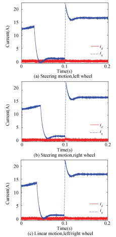
The d-q axis current is given in Fig. 6. The feature amplitudes are shown in Table 2. It can be found that when the demagnetization amount DB is 30%, the q-axis current iq of the right wheel reaches the rated value of 17 A. Since the current feedforward disturbance compensation method is adopted in this work, when the demagnetization increases, the system disturbance will further increase, which will lead to a smaller torque output value. In order to smooth the torque ripple, according to Eq. (12), the current will increase, so that the output torque matches the load torque. If the demagnetization is increased continuously, the feedforward current will further increase and the q-axis current exceeding the rated value finally. Therefore, this paper verifies the effectiveness in the range of 0-30% demagnetization only.
|
Fig.6 The d-q axis current using ESO-FOC method at 30% demagnetization |
| Table 2 d-q axis current using ESO-FOC method at 30% demagnetization |
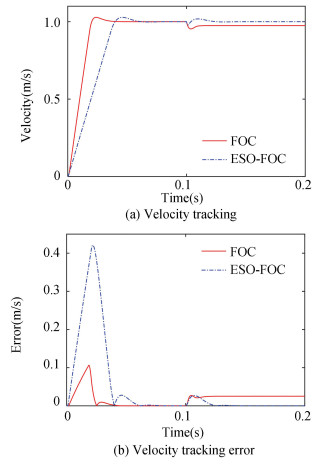
The linear motion speed tracking effect at 30% demagnetization DB is shown in Fig. 7. Error of linear velocity tracking of robot in linear motion is listed in Table 3. It can be seen that the basic FOC method produces a stable speed tracking error in the case of demagnetization, and the speed tracking error e is 2.5×10⁻² m/s during stable operation stage. The ESO-FOC method designed in this work can finally reduce the speed tracking error e to 2.529×10⁻⁶ m/s in a short time, and reach a stable operating state after 0.15 s with good robustness.
|
Fig.7 Velocity tracking effect of linear motion with 30% demagnetization |
| Table 3 Error of linear velocity tracking of robot in linear motion |
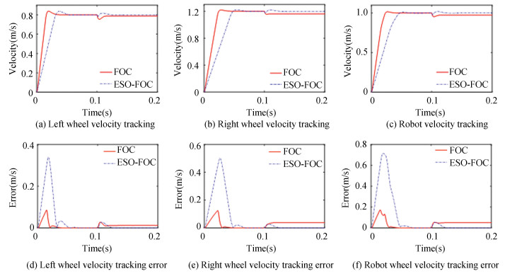
In Fig. 8, the steering velocity tracking results under 30% demagnetization of basic FOC and ESO-FOC are given. The final stable velocity under FOC control is less than the reference velocity in the case of demagnetization, while the final stable velocity under ESO-FOC control is close to the reference velocity. Since the observer needs to estimate the disturbance of the vector control system, due to the sudden increase of the current, the ESO produces a current mutation when estimating the demagnetization disturbance, resulting in a velocity mutation. The designed system will have a delayed phenomenon in the start-up stage of 0-0.1 s, but its duration is short and the momentarily delay will not affect the convergence velocity of the system after loading. It is believed that the system convergence is good.
|
Fig.8 Velocity tracking effect of steering motion with 30% demagnetization |
It can also be found from Fig. 8 that there is a stable error in FOC, and the error generated by ESO-FOC is smaller. The feature amplitudes are listed in Table 4. Compared with the basic FOC control system, ESO-FOC will have a large error in a short time during the start-up phase before loading, but it will quickly reach a stable state with a small error. After loading, the designed system and the basic FOC system get a stable situation in a short time. In the stable operation state at 0.2 s, the FOC method will produce a stability error of 5×10⁻²m/s, while the ESO-FOC method can reduce the error e to 3.176×10⁻⁵m/s.
| Table 4 Error of linear velocity tracking of robot in steering motion |
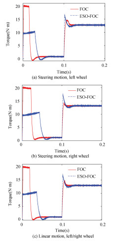
In Fig. 9, the motor torques under the two methods are given when the demagnetization DB is 30%. The feature amplitudes are shown in Table 5. Adding current feedforward to the basic FOC method can realize the demagnetization compensation of the torque Te.
|
Fig.9 Motor torque in two ways at 30% demagnetization |
| Table 5 Motor torque in two ways at 30% demagnetization |
However, the tracking error curve in Fig. 8 shows that there still is speed tracking error. It is because the demagnetization effect E2 cannot be directly obtained by the relationship between torque and current, according to Eq. (22). It is necessary to add ESO to observe the uncertain disturbance because ESO can observe system disturbances in real time only.
From Fig. 9, it can be seen that in the no-load starting stage of 0 to 0.1 s, the FOC system has a large torque ripple under the influence of demagnetization, while the ESO-FOC system weakens the demagnetization disturbance under the action of feedforward current, and the torque ripple is smaller. Under loading, these two methods have basically the same convergence rate, and the torque ripple is small, which indicates that the designed control system has good real-time performance and stability.
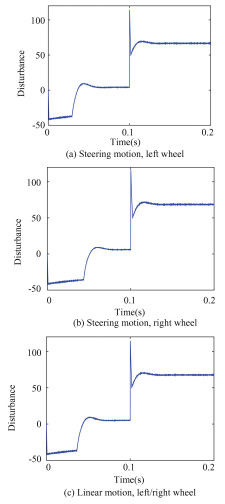
The observation results of the system disturbance are shown in Fig. 10. It can be seen that the reversed disturbance will occur during the loading stage from 0 s to 0.05 s, due to the coordinate transformation of the motor control system, which is consistent with the motor analysis in the starting state. At 0.1 s, the disturbance changes abruptly due to the sudden application of the load. This presentation is consistent with the current change. In the start-up phase, the disturbance convergence speed slows down due to the increase of demagnetization, then, the system disturbance of two methods can reach a stable state at a faster speed after 0.05 s, which also indicates that the designed current feedforward compensation strategy is reliable.
|
Fig.10 System disturbance at 30% demagnetization |
After loading, the disturbance of the steady state increases synchronously with the increase of the demagnetization. According to Eq. (12), the changing trend is consistent with the results of theoretical analysis, which indicates that the designed ESO has good stability when observing the demagnetization disturbance, and the obtained observation results have high reliability.
The specific data of ESO observation system disturbance are given in Table 6. The increments of disturbance values are 6.8192 and 8.0624, respectively. The left wheel disturbance increments of steering motion are 7.1377 and 8.3498 respectively, and the right wheel disturbance increments are 6.7751 and 8.744, respectively. With the increase of demagnetization, the increment of disturbance value increases proportionally, but there is still a certain increase compared with the increment of demagnetization. This is because PMSM is a highly coupled nonlinear system, and the obtained disturbance value comes from the superposition of multiple system disturbances. According to the speed tracking results, the observed disturbance value is fitter for the current compensation module. Therefore, the increment of the disturbance value conforms to the variation of the demagnetization.
| Table 6 Observation results of system disturbance at 0.2 s |
4 Conclusions
In this paper, a current feedforward vector control system based on ESO is designed for reducing the demagnetization error of the mobile robot driven by the hub motor, and the effectiveness of the system is verified by simulation experiments.
1) The influence of irreversible demagnetization on robot speed tracking is transformed into the change of internal parameters of permanent magnet synchronous motor, and the influence of demagnetization on control system is quantitatively studied.
2) The motions of differential drive are decomposed into linear motion and rotation motion. The compensation effect of motor demagnetization error under different motion modes is analyzed respectively. The robustness of the designed current feedforward control method is tested.
3) The vector control system based on ESO has the characteristics of real-time monitoring of the uncertain disturbance of the system. With the current feedforward method, the demagnetization error can be weaken quickly and stably, and the speed tracking accuracy of the mobile robot in the case of motor demagnetization is improved.
| [1] |
Zhang L, Wang Z H, Sun F C, et al. Fault-tolerant control for intelligent four-wheel-independently-actuated electric vehicles under complete steer-by-wire system failure. Journal of Mechanical Engineering, 2021, 57(20): 141-152. DOI:10.3901/JME.2021.20.141 (  0) 0) |
| [2] |
Li J. Research status and development prospect of electric vehicles based on hub motor. Proceedings of the 2018 China International Conference on Electricity Distribution (CICED). Piscataway: IEEE, 2018: 126-129. DOI:10.1109/CICED.2018.8592598
(  0) 0) |
| [3] |
Shangguan X F, Zhou J L, Jiang S Y. Demagnetization of dual-rotor permanent magnet induction motor with double squirrel cage during the starting process. Electric Machines and Control, 2019, 23(12): 126-134. (  0) 0) |
| [4] |
Zhu L, Zhu X Y, Zuo Y F. Overview of fault-tolerant technologies of rotor permanent magnet brushless machine and its control system for electric vehicles. Proceedings of the CSEE, 2019, 39(6): 181-699. (  0) 0) |
| [5] |
Lin H. Direct control of current vector for surface-mounted permanent magnet synchronous motor. Proceedings of the CSEE, 2011, 31(z1): 288-294. (  0) 0) |
| [6] |
Pramod P, Zhang Z, Namburi K M P K. Effects of position sensing dynamics on feedforword current control of permanent magnet synchronous machines. Proceedings of the 2018 IEEE Energy Conversion Congress and Exposition (ECCE). Piscataway: IEEE, 2018: 3436-3441. DOI:10.1109/IEMDC.2017.8002221
(  0) 0) |
| [7] |
Dieterle O, Greiner T, Heidrich P. Feedforward compensation of torque harmonics in permanent magnet synchronous machines. IFAC-PapersOnLine, 2020, 53(2): 8783-8789. DOI:10.1016/j.ifacol.2020.12.1382 (  0) 0) |
| [8] |
Veeser F, Braun T, Kiltz L, et al. Nonlinear modelling, flatness-based current control, and torque ripple compensation for interior permanent magnet synchronous machines. Energies, 2021, 14(6): 1-14. DOI:10.3390/en14061590 (  0) 0) |
| [9] |
Yan Y, Liu R, Shi T N, et al. Friction compensation for permanent magnet synchronous motors based on adaptive back-stepping control. Proceedings of the CSEE, 2013, 33(33): 76-84. (  0) 0) |
| [10] |
Zhong Z M, Jiang S, Kang J S, et al. A harmonic voltage and current coupling permanent magnet synchronous motor model and feedforward control. Transactions of China Electrotechnical Society, 2017, 32(18): 131-142. (  0) 0) |
| [11] |
Yan Y, Huang W X. Research on delay compensation strategy of permanent magnet synchronous motor based on closed-loop current prediction. Proceedings of the CSEE, 2022, 42(10): 3786-3796. (  0) 0) |
| [12] |
Yin K X, Gao L, Fu W H. An improved prediction control model for PMSM with active disturbance rejection and feed-forward control strategy. Journal of Xi'an Jiaotong University, 2021, 55(4): 29-38. DOI:10.7652/xjtuxb202104004 (  0) 0) |
| [13] |
Wang C C, Yang G L, Chen Q Y, et al. Speed ripple suppression based on an adaptive disturbance observer for collaborative robot joint. Robot, 2023, 45(1): 48-57. DOI:10.13973/j.cnki.robot.210412 (  0) 0) |
| [14] |
Liu X B, Fu Z Y, Liu Z, et al. Vector control of PMSM based on disturbance compensation and nonsingular terminal sliding mode. Journal of Northwestern Polytechnical University, 2022, 40(2): 316-322. DOI:10.1051/jnwpu/20224020316 (  0) 0) |
| [15] |
Xia J, Li Z, Yu D, et al. Robust speed and current control with parametric adaptation for surface-mounted PMSM considering system perturbations. IEEE Journal of Emerging and Selected Topics in Power Electronics, 2021, 9(3): 2807-2817. DOI:10.1109/JESTPE.2020.3015288 (  0) 0) |
| [16] |
Bobtsov A A, Pyrkin A A, Ortega R, et al. A robust globally convergent position observer for the permanent magnet synchronous motor. Automatica, 2015, 61: 47-54. DOI:10.1016/j.automatica.2015.07.032 (  0) 0) |
| [17] |
Song W X, Ren H, Ye H. Position sensorless control of dual three phase permanent magnet synchronous motor based on MRAS. Proceedings of the CSEE, 2022, 42(3): 1164-1174. (  0) 0) |
| [18] |
Wang L L, Dong L Y, Ma D, et al. Active disturbance rejection tracking control of wheeled mobile robots under sliding and slipping conditions. Control Theory & Applications, 2020, 37(2): 431-438. DOI:10.7641/CTA.2019.80974 (  0) 0) |
| [19] |
Wang Z, Zhou M L, Xie B R, et al. A control strategy of PMSM based on D-axis current regulator under square wave. Proceedings of the CSEE, 2022, 42(3): 1154-1164. (  0) 0) |
| [20] |
Zhao X M, Wang H L, Zhu W B. Feedback linearization control of permanent magnet linear synchronous motor based on adaptive fuzzy controller and nonlinear disturbance observer. Control Theory & Applications, 2021, 38(5): 595-602. DOI:10.7641/CTA.2020.00381 (  0) 0) |
| [21] |
Liao C C, Zhou L, Pan C Z, et al. Parameter optimization design of modified repetitive control system based on equivalent input disturbance compensation. Control Theory & Applications, 2022, 39(4): 653-662. DOI:10.7641/CTA.2021.10228 (  0) 0) |
 2024, Vol. 31


