Better thermal management is necessary to increase the reliability of electronic components. Heat sinks help in thermal management[1]. The main difficulty is to maximize thermal efficiency while using a lighter heat sink. Weight reduction is important in applications like aerospace. A superior option is the passive heat sink, which needs less maintenance[2]. Despite significant advancements in heat sink creation, the thermal control of integrated and tiny devices presents challenges mostly because of rising power densities[3]. Coating is a potential approach to enhance substrate surface characteristics[4]. Heat dissipation efficiency of a component can also be improved by coating[5]. Graphene has excellent heat conduction properties[6]. Among the materials available, suspended single layer graphene has the highest heat conductivity[7]. Because of graphene's remarkable characteristics, it can be employed to considerably improve thermal performances of heat sink by coating[8]. Immersion coating is very cost-effective for thin film coating[9]. Direct apply and cure method is also widely used in experimental research[10].
Extensive research has been conducted in recent years to assess the appropriateness of graphene for applications such as nano fillers, thermal interface materials, and heat sinks[11-14]. Numerical simulation done to understand the effects of adding MWCNT nano particles with paraffin and coupling it with fins significantly enhanced heat transfer and helped in effective thermal management of photovoltaic thermal system[15-16]. Photovoltaic thermal system is essential to generate electricity and to save heat in a sustainable way. The utilization of confined jets and turbulators to cool the PV cell proved to be effective in maintaining the panel temperature[17].
Free convection cooling in electronic devices widely uses finned aluminium surfaces. Particularly the rectangular fins projecting from the rectangular bases are the most popular one and applied in many electronic devices. The reason behind the choice is that rectangular fins provide trouble-free and cost-effective solution for thermal management issues[18]. The orientation of the fins has a significant impact on the quality of heat transmission. Vertical plate fins on flat horizontal base provide excellent heat dissipation capabilities[19]. Taguchi experimental design can be utilized to evaluate the influence of height, width, stream wise and span wise spacing on the heat dissipation efficiency of the heat sink[20]. Surface preparation procedures, for example sand blasting, considerably enhanced mechanical qualities, but little is known about their impact on thermal conductivity enhancement[21]. Aluminium oxide, silicon carbide, and quartz abrasives can be employed in the sand blasting process to impart the desired level of roughness to the treated surfaces[22-24].The goal of this analysis is to assess the effect of abrasive blasting, heat treatment, and graphene coating on the heat dissipation capabilities of plate fin heat sinks made of AlSi10Mg. Using experimental analysis, the most influential factor for heat transfer augmentation under natural convection conditions was discovered.
1 Material and Methods 1.1 MaterialThe coating substance was a combination of acrylic resin and graphene. Graphene (purity 99%, thickness 5-10 nm, bulk density 0.1g/cm3, average lateral dimension 10 μm) was supplied by Adnano labs, Machenahalli, Karnataka, India. Acrylic resin and hardener was supplied by AMK polymers, Chennai, India. Heat sinks fabricated from Aluminum plates (AlSi10Mg, Pratham traders, Chennai, India) were employed as the coating substrate.
Plate fin heat sinks with six fins were fabricated by milling process. The material used was AlSi10Mg. Totally seven heat sinks were fabricated and they are named as S1, S2, ..., S7, representing the sample numbers. The measurements of all the seven heat sinks are the same. Table 1 shows the processings performed on the samples.
| Table 1 Changes made on samples |
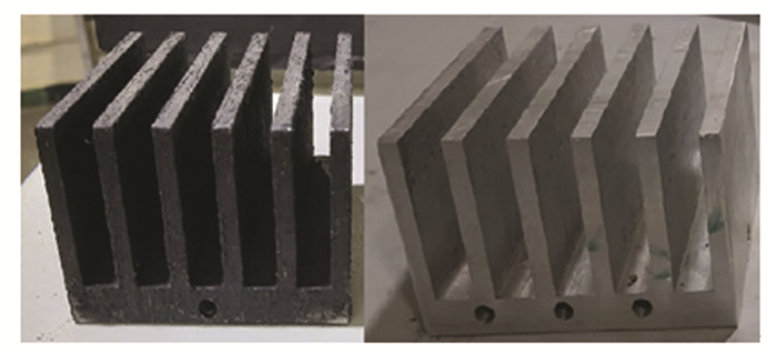
Aluminium oxide particles are blasted all over the surface for 0.15 MPa in S1, 0.3 MPa in S2 and 0.5 MPa in S3. Sample S4 was heat treated at 250 ℃, S5 was heat treated at 350 ℃ and S6 was heat treated at 450 ℃. Sample S7 had no abrasive blasting. Graphene was mixed with acrylic resin and coated on heat sink samples S1-S7. Fig. 1 shows the image of the fabricated heat sink both coated and uncoated.
|
Fig.1 Fabricated heat sink both coated and uncoated |
1.2 Assessment of Thermal Conductivity
Using a thermal conductivity meter, the thermal conductivity was assessed (DTC 300, TA instruments, New castle, USA). The plate fin heat sink had thermocouples attached to it. Abrasive-blasted and graphene-coated, heat-treated and graphene-coated, and bare aluminum heat sinks were used for measurement. The coating's thermal conductivity was calculated using Eq.(1) below.
| $ L_T / K_T=L_1 / K_1+L_2 / K_2 $ | (1) |
where, correspondingly, L1, L2, and LT represent the coating thickness, substrate thickness, and total thickness. K stands for heat conductivity. The coating thickness was measured with a coating thickness metre. The coating thickness was found to be 0.5 mm.
1.3 Abrasive BlastingAbrasive blasting was done using Blastech sand blasting machine BL24650. The capacity of the machine is 20 L, height of the blasting machine is 711 mm, diameter of the blasting cylinder is 254 mm and the abrasive holding capacity of the machine was around 38 kg.Dry blasting and wet blasting are two methods of abrasive blasting. Dry blasting can be done with aluminium oxide, silicon carbide, sand, and metallic grit. Wet blasting is appropriate for sand and glass beads. A high pressure stream of abrasive particles was hit on the surface during the abrasive blasting procedure. In this work, dry blasting was chosen, Aluminium oxide with a mesh size of 60 was employed for abrasive blasting. The specimen was placed in a holder. That is powered by motor to guarantee that the nozzle moves at a steady pace. The pressure regulator helps to maintain the required pressure.
1.4 Heat TreatmentHeat treatment was performed with the help of resistance furnace. 250 ℃, 350 ℃ and 450 ℃ were the temperature utilized for heat treatment. 3 h was set as holding time for all samples. After 3 h, the heat sink sample was subjected to progressive cooling inside the furnace. The resistance furnace was chosen for the heating procedure because of its exceptional capacity to uniformly heat the work item. High-temperature heating is also achievable with a resistance furnace.
1.5 Coating ProcessElectric spray gun is utilized to finish the coating process. The process followed for coating is shown in Fig. 2. Modified acrylic silicone resin RB-237 (Adhere Bonds coats, Chennai, India) was taken as matrix. Graphene was added up to 1 wt.% and the resin with graphene mixture was stirred using high speed stirrer for 5 min. The speed of stirring was set up to 1000 r/min. The stirred mixture was applied on the heat sink using electric spray gun.

|
Fig.2 Coating of heat sink (a) Graphene nano powder; (b) Modified acrylic silicon resin added with Graphene powder; (c) Resin and Graphene mixture after stirring process; (d) Graphene and resin mixture coated on heat sink. |
1.6 Experimental Setup
The heat sink's free convection ability was investigated using an experimental configuration. The temperature was monitored until the heat sink achieves the safest junction temperature of 60 ℃.
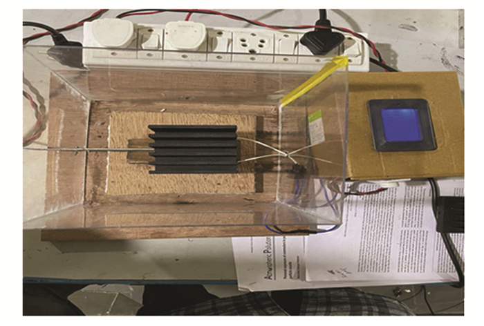
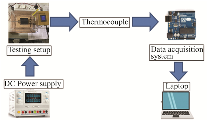
A specially created test bed was used to assess the heat sink's abilities to transmit heat under natural convection. Fig. 3 and Fig. 4 show the test bed and the entire experimental setup. Acrylic polymers that are 4 mm thick were used to build a specific test room that measures 50 cm×50 cm. The test cabinet reduced airflow disruptions and produced a uniform radiation background.
|
Fig.3 Actual test bed with heat sink |
|
Fig.4 Schematic view of the experimental setup |
A power supply unit, a thermostat heater plate, a data gathering system, and thermocouples are required for the experiment. The external dimensions of heat sink were 80 mm×75 mm×50 mm. Thermocouples were used to monitor temperature distributions. An Arduino-based data collection system was used to log the data into a PC. The thermostat heater was the heat source. The junction temperature of the real life electronic components were replicated with the help of this insulated thermostat heater. The lab's temperature was 33 ℃. Different input powers (15 W, 25 W and 35 W) were used to evaluate the heat sink.
Thermal dissipation performance may be assessed by applying various heat inputs to heat sink samples and measuring the temperature rise every 30 s for 20 min using a thermocouple connected to the heat sink. Better thermal performance may be found by monitoring the heat sink samples surface temperature. The sample which reaches junction temperature slowly is considered as better performing and the sample which reaches junction temperature quickly is considered as poor performing[25].
2 Results and Discussion 2.1 Characteristics of GrapheneTable 2 and Fig. 5 show the characteristics of graphene used in the present work. From the Raman spectrum shown in Fig. 5 (b), it can be observed that three different absorption peaks were visible. This confirms that the graphene used in this experiment is multilayer category.
| Table 2 Properties of graphene nano particles used for coating |

|
Fig.5 SEM image and characterization using Raman spectroscopy |
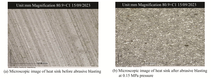
Fig. 6 (a) shows the microscopic image of a portion of heat sink made of AlSi10Mg before doing abrasive blasting. Fig. 6(b) shows the microscopic image of abrasive blasted heat sink. The effect of abrasive blasting can be clearly observed from the image. The surface roughness created because abrasive blasting will have positive impacts since the rough surface increases the surface area and enhances the heat transfer.
|
Fig.6 Microscopic images of heat sink before and after abrasive blasting |
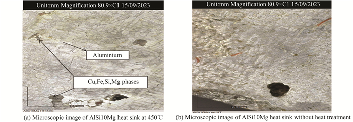
When there is no heat treatment and when heat treatment is done at low temperatures, we can see the fine precipitates formation in aluminium. Fig. 7 (a) shows the image when heat treatment was done at 450 ℃.The precipitate size increased and also number of precipitates got reduced.Fig. 7 (b) shows the microscopic image of sample without heat treatment.
|
Fig.7 Microscopic image of heat sink with and without heat treatment |
2.2 Heat Conduction
Table 3 shows the heat conduction capacity of coated and uncoated plate fin heat sinks. The thermal conductivity of untreated heat sink (S7) was 112.5 W/(m·K). The thermal conductivity of heat sink after abrasive blasting at 0.5 MPa and graphene coating for 0.5 mm (S3) was 112.3 W/(m·K), abrasive blasting at 0.15 MPa and graphene coating for 0.5 mm (S1) was 111.2 W/(m·K) and abrasive blasting at 0.3 MPa and graphene coating for 0.5 mm (S2) was 111.6 W/(m·K). From the results, it is clear that there is no significant change in thermal conductivity after abrasive blasting and graphene coating.
| Table 3 Thermal conductivity of heat sinks |
The thermal conductivity of heat sink after heat treating at 450 ℃ and graphene coating for 0.5 mm (S6) was 114.2 W/(m·K), heat treating at 350 ℃ and graphene coating for 0.5 mm (S5) was 113.7 W/(m·K), and heat treating at 250 ℃ and graphene coating for 0.5 mm (S4) was 113.3 W/(m·K). From the results, it is clear that there is an improvement in thermal conductivity when heat treatment is done for 450 ℃.
From the experimental observations, it is clear that S3 (abrasive blasting at 0.5 MPa and graphene coating for 0.5 mm) and S6 (heat treating at 450 ℃ and graphene coating for 0.5 mm) only have significant results, therefore graphs were drawn and compared to S7(untreated and only graphene coated for 0.5 mm).
Fig. 8 (a) shows the experimental results (charging and discharging cycle) of untreated heat sink. At 15 W heat input, the heat sink reached junction temperature of 60 ℃ in around 2025 s. As heat input increased, the time needed to reach the junction temperature got reduced. For the maximum heat input of 45 W, the junction temperature reached in less than 600 s. Therefore, it is clear that the charging cycle of uncoated heat sink was maximum at low heat input. The fastest discharge cycle was for 45 W heat input. Therefore, it is obvious from the result that at high heat input the discharging cycle was fast for the uncoated heat sink.

|
Fig.8 Charging and discharging cycles of untreated and treated heat sink |
Fig. 8 (b) shows the charging and discharging cycle of S3 (abrasive blasting at 0.5 MPa and graphene coating for 0.5 mm). At the low heat input of 15 W, the heat sink reached junction temperature of 60 ℃ in 1890 s which is 160 s less when compared to the uncoated heat sink.
Fig. 8 (c) shows the charging and discharging cycle of S6 (heat treating at 450 ℃ and graphene coating for 0.5 mm). At 15 W heat input, the time taken to reach junction temperature of 60 ℃ was around 3900 s, which was 1850 s more than that of uncoated heat sink and 2010 s more than that of abrasive blasted and graphene coated heat sink. When the high heat input of 45 W was observed, the heat sink reached junction temperature in very less time. It was almost same that of the uncoated heat sink.When the high heat input of 45 W was considered, the abrasive blasted and graphene coated heat sink took less time to reach junction temperature and also returned to the room temperature quickly(discharge cycle). Therefore, the obtained results show that the abrasive blasted and graphene coated heat sink was comparatively better when high heat input conditions were used.
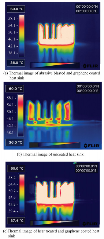
Fig. 9 (a) shows the thermal image of abrasive blasted and graphene coated heat sink. Because of coating, the enhanced heat transfer can be observed clearly in the thermal image. Fig. 9 (b) reveals the thermal image of the uncoated heat sink. The fastest discharge cycle was observed with a 45 W heat input, and the slowest discharge cycle was observed with a 15 W heat input. From this, it is clear that the heat treatment process followed by graphene coating gives the lengthy charging cycle (the time taken to reach junction temperature) when low heat input of 15 W is given. Considering the high heat input conditions, the abrasive blasted and graphene coated heat sink performed better when compared to the other types of heat sinks. Fig. 9 (c) shows the thermal image of heat treated and graphene coated heat sink. It can be observed that the heat transfer is maximum when heat treatment and graphene coating are done.
|
Fig.9 Thermal images showing heat dissipation performance of heat sink with and without treatment processes |
3 Conclusions
In this research work, heat transfer efficiency of aluminium heat sink fabricated by milling process in the shape of plate fin was compared with abrasive blasted and graphene coated heat sink initially, and then with heat treated and graphene coated heat sink finally. Natural convection heat transfer was evaluated with the help of an experimental set-up. Heat input was given in the range of 15 W-45 W. 60 ℃ was considered as the junction temperature. The changes in temperature with respect to the time were monitored for every 30 s with the help of thermocouples connected to the data logging system.
From the findings of the experiment, it can be concluded that the charging cycle increased 2 folds for heat treated and graphene coated heat sink at 15 W heat input. Therefore, junction temperature can be increased to double the time when low heat put is considered, which indirectly means that the life cycle can be increased 2 times. The abrasive blasted and graphene coated heat sink provided an improvement in charging cycle of around 1.3 to 1.4 times when high heat input of 45 W is applied. However, when 15 W heat input is considered, abrasive blasted and graphene coated heat sink does not show much improvement. Therefore, it is obvious from the experimental investigation that when the heat input is in 15 W range, the heat treated and 0.5 mm graphene coated heat sink can increase the junction temperature in turn, which can definitely increase the service life and reliability. The results obtained are matching with the findings of Kung and Yang[26]. In their work, they proved that heat dissipation improves with graphene coating.
Future work of this study would be on the 3D printed AlSi10Mg heat sink. The effect of graphene coating for various thickness and surface treatment on the thermal management abilities will be studied.
| [1] |
Zhang X. Software system research in post-Moore's law era: A historical perspective for the future. Science China Information Sciences, 2019, 62: 196101. DOI:10.1007/s11432-019-9860-1 (  0) 0) |
| [2] |
Regis D, Hubert G, Bayle F, et al. IC components reliability concerns for avionics end users. 2013 IEEE/AIAA 32nd Digital Avionics Systems Conference (DASC). Piscataway: IEEE, 2013: 2C2-1-2C2-9. DOI: 10.1109/DASC.2013.6712539.
(  0) 0) |
| [3] |
Jafari D, Wits W W. The utilization of selective laser melting technology on heat transfer devices for thermal energy conversion applications: A review. Renewable and Sustainable Energy Reviews, 2018, 91: 420-442. DOI:10.1016/j.rser.2018.03.109 (  0) 0) |
| [4] |
Chattopadhyay D K, Raju K V S N. Structural engineering of polyurethane coatings for high performance applications. Progress in Polymer Science, 2007, 32(3): 352-418. DOI:10.1016/j.progpolymsci.2006.05.003 (  0) 0) |
| [5] |
Ganguli S, Roy A K, Anderson D P. Improved thermal conductivity for chemically functionalized exfoliated graphene/epoxy composites. Carbon, 2008, 46(5): 806-817. DOI:10.1016/j.carbon.2008.02.008 (  0) 0) |
| [6] |
Lim M, Lee S S, Lee B J. Near-field thermal radiation between graphene-covered doped silicon plates. Optics Express, 2013, 21(19): 22173-22185. DOI:10.1364/OE.21.022173 (  0) 0) |
| [7] |
Baladin A A, Ghosh S, Bao W, et al. Superior thermal conductivity of single-layer graphene. Nano Letter, 2008, 8: 902-907. DOI:10.1021/nl0731872 (  0) 0) |
| [8] |
Hsieh C T, Chen W. Water/Oil repellency and work of adhesion of liquid droplets on graphene oxide and graphene surfaces. Surface and Coatings Technology, 2011, 205(19): 4554-4561. DOI:10.1016/j.surfcoat.2011.03.128 (  0) 0) |
| [9] |
Scriven L E. Physics and applications of DIP coating and spin coating. MRS online Proceedings Library, 1988, 121: 717-729. DOI:10.1557/PROC-121-717 (  0) 0) |
| [10] |
Tong Y, Bohm S, Song M. Graphene based materials and their composites as coating. Austin Journal of Nanomedicine & Nanotechnology, 2013, 1(1): 1003. (  0) 0) |
| [11] |
Lin Y F, Hsieh C T, Wai R J. Facile synthesis of graphene sheets for heat sink application. Solid State Sciences, 2015, 43: 22-27. DOI:10.1016/j.solidstatesciences.2015.03.010 (  0) 0) |
| [12] |
Im H, Kim J. Thermal conductivity of a graphene Oxide-Carbon nanotube hybrid/epoxy composite. Carbon, 2012, 50(15): 5429-5440. DOI:10.1016/j.carbon.2012.07.029 (  0) 0) |
| [13] |
Li Q, Guo Y, Li W, et al. Ultrahigh thermal conductivity of assembled aligned multilayer graphene/epoxy composite. Chemistry of Materials, 2014, 26(15): 4459-4465. DOI:10.1021/cm501473t (  0) 0) |
| [14] |
Song S H, Park K H, Kim B H, et al. Enhanced thermal conductivity of epoxy-graphene composites by using non-oxidized graphene flakes with non-covalent functionalization. Advanced Materials, 2012, 25(5): 732-737. DOI:10.1002/adma.201202736 (  0) 0) |
| [15] |
Sheikholeslami M, Khalili Z, Scardi P, et al. Concentrated photovoltaic cell equipped with thermoelectric layer in presence of nano fluid flow within porous heat sink: Impact of dust accumulation. Sustainable Cities and Society, 2023, 98: 104866. DOI:10.1016/j.scs.2023.104866 (  0) 0) |
| [16] |
Sheikholeslami M. Numerical investigation for concentrated photovoltaic solar system in existence of paraffin equipped with MWCNT nano particles. Sustainable Cities and Society, 2023, 98: 104901. DOI:10.1016/j.scs.2023.104901 (  0) 0) |
| [17] |
Sheikholeslami M, Khalili Z. Environmental and energy analysis for photo-voltaic-thermoelectric solar unit in existence of nano fluid cooling reporting CO2 emission reduction. Journal of Taiwan Institute of Chemical Engineers, 2024, 156: 105341. DOI:10.1016/j.jtice.2023.105341 (  0) 0) |
| [18] |
Senthilkumar R, Nandhakumar A J D, Prabu S. Analysis of natural convective heat transfer of nano coated aluminium fins using Taguchi method. Heat and Mass Transfer, 2013, 49: 55-64. DOI:10.1007/s00231-012-1063-1 (  0) 0) |
| [19] |
Welling J R, Wooldridge C N. Free convection heat transfer coefficients from vertical fins. Journal of Heat and Mass Transfer, 1965, 87: 439-444. DOI:10.1115/1.3689135 (  0) 0) |
| [20] |
Yakut K, Alemdaroglu N, Sahin B, et al. Optimum design-parameters of a heat exchanger having hexagonal fins. Applied Energy, 2006, 83(2): 82-98. DOI:10.1016/j.apenergy.2005.01.007 (  0) 0) |
| [21] |
Miturska-Baranska I, Rudawska A, Doluk E. The influence of sand blasting process parameters of aerospace aluminium alloy sheets on adhesive joints strength. Materials, 2021, 14(21): 6626. DOI:10.3390/ma14216626 (  0) 0) |
| [22] |
Rudawska A, Danczak I, Müller M, et al. The effect of sandblasting on surface properties for adhesion. International Journal of Adhesions and Adhesives, 2016, 70: 176-190. DOI:10.1016/j.ijadhadh.2016.06.010 (  0) 0) |
| [23] |
Rudawska A, Miturska I. Impact study of single stage and multi stage abrasive machining on static strength of lap adhesive joints of mild steel. MATEC Web of Conferences. Paris: EDP Sciences, 2018, 244: 02006. DOI: 10.1051/matecconf/201824402006.
(  0) 0) |
| [24] |
Gomes A L, Castillo-Oyagüe R, Lynch C D, et al. Influence of sandblasting granulometry and resin cement composition on microtensile bond strength to zirconia ceramic for dental prosthetic frameworks. Journal of Dentistry, 2013, 41(1): 31-41. DOI:10.1016/j.jdent.2012.09.013 (  0) 0) |
| [25] |
Rodríguez-Salinas J, Hernández M B, Cruz L G, et al. Enhancing electrical and thermal properties of Al6061 parts by electrophoresis deposition of multi-walled carbon nanotubes. Coatings, 2020, 10(7): 656. DOI:10.3390/coatings10070656 (  0) 0) |
| [26] |
Kung F, Yang M C. Improvement of the heat-dissipating performance of powder coating with graphene. Polymers, 2020, 12(6): 1321. DOI:10.3390/polym12061321 (  0) 0) |
 2024, Vol. 31


