2. 哈尔滨学院 信息工程学院, 哈尔滨 150080;
3. 江苏恒神股份有限公司 工程技术中心, 江苏 丹阳 212314
2. School of Software, Harbin University, Harbin 150080, China;
3. Engineering Technology Center, Jiangsu Hengshen Co., Ltd, Danyang 212314, China
相比于金属材料,复合材料以其比模量高、比刚度大、可设计性强和环境鲁棒性好等优质特性,在航空、航天、汽车、舰船、机械、土建以及军事等实际工程中得到广泛应用[1-3],而复合材料结构体(如雷达整流罩、飞机头部等)的应用需求通常存在结构功能与轻量化等诸多困难.构件结构的轻量化可通过以下3种方法来实现:1) 采用高比强度和高比模量的复合材料体系替代金属材料,并通过少用材料实现结构轻量化; 2) 通过结构构型设计,将复合材料的优势承载方向沿结构的传力路径布置,剔除非传力区材料,实现结构轻量化; 3) 采用复合材料整体成型技术,实现复杂结构的整体制备,达到结构减重的目的.应用上述方法,在采用轻质复合材料基础上,进一步挖掘其结构构型设计,采用以复合材料带为基材的网状薄壳结构,以进一步挖掘复合材料构件成型的构造规律和轻量化.文献[4]提出一种利用弯折薄木条叠接钻孔铆固法生成木条网壳的轻量化方法,该方法因在木条上钻孔而破坏了木纤维本身的弯折曲率和成型姿态,并存在较大的结构反力,加之木条纤维受环境温湿度等的影响较大,构件成型建模的各个因素复杂,导致建模求解困难或发散.
本文则以雷达整流罩为原型,采用受环境因素影响小的预浸复合材料带为构型基材,以单位球面网壳结构为主体,在笛卡尔坐标系下的单位球为映射基点,研究将文献[4]的多参量、高阶导数简化为仅有θ和φ两个参量的简化微分模型,提出基于测地线网的薄壳建模方法(测地线网壳模型).在选材上,采用轻质、高强的预浸单向连续纤维复合材料带;在构型上,结构呈网状多孔,形成曲面网架.这些网孔不是传统的满铺工艺基础上,再通过移除需开孔处材料获得,而是沿构件曲面的测地曲线连续生成测地网架,以避免常规的切除网孔部材料成孔而破坏纤维材料的连续性[5].在工艺上,采用工业机器人缠绕/铺放工艺取代传统的手工工艺,经加热固化成型,也可根据功能需要进一步进行蒙皮、功能材料和传感器埋设技术等工艺完成后续制造[6-7],达到结构成型-功能实现的自动化和轻量化等目的[8].
1 曲面网壳建模的相关条件和概念曲面网壳理论是以古典微分几何、广义相对论的基本条件和壳体理论的基本假设为基础的[9].曲面测地线(Geodesic)即短程线, “短程线”一词来源于地球测量学, 即连接球面上两点的最短距离.据此原理,用过球心和这两点的平面截球,在球面上所得截线成为大圆,两点在大圆上的连线为最短距离.它是将Euclid三维空间里,两点之间直线最短这一基本概念推广到Riemann空间的曲面上,而测地线的微分方程是保证纤维复合材料带轨迹最佳的关键;薄壳是曲面的薄壁结构,即壳体的厚度远小于壳体曲面的最小曲率半径,称为薄壳,否则称为厚壳,按曲面生成的外形分为筒壳、球形壳、双曲扁壳和旋转面壳等[10].而曲面网壳是由测地线交织成网并具有一定厚度的壳体结构.根据测地线的定义在单位球面上直接推导测地线弧算法.对于单位球面上的测地线,有:扭转张量为零,且测地线上各点的李导数也为零的性质[4],如式(1) 和式(2) 所示.
| $ T_{ij}^k=0, $ | (1) |
| $ [X,Y]=0. $ | (2) |
从而可导出直接用计算机编程计算出各位置向量的测地线弧方程,为产品的自动化生产提供可能.
2 系统建模依据高斯微分几何[11],以球心为坐标原点O(0, 0, 0),建立笛卡尔直角坐标系.
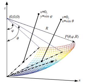
2.1 坐标参数设定及球面方程建立设3个坐标轴分别用x, y, z表示,球面上任一点的坐标为P(x,y,z),矢量方程在x轴、y轴和z轴的方向向量分别用i, j, k表示,球半径为R,并用θ和φ表示从z轴到位置向量P(x, y)的经纬线跨距的曲率坐标(右手法则),如图 1和图 2所示,因该曲面是单位球面,故点P坐标用参数方程可表示为式(3),其中,半径R=1,x,y为未知变量.在笛卡尔坐标系中,当z=-1时,在xoy平面上,两个相交的椭圆方程如式(4) 所示,其中,a和b分别表示椭圆的长半轴或短半轴.

|
图 1 单位球面上点P的θ和φ参数表示 Figure 1 Parameter representation of P, θ and φ on the unit sphere |

|
图 2 点P在xoy平面上投影位置 Figure 2 The projection position of point P on xoy |
| $ z\left( {x,y} \right) = \pm \sqrt {{R^2} - {x^2}\left( {\theta ,\varphi ,R} \right) - {y^2}\left( {\theta ,\varphi ,R} \right)} , $ | (3) |
| $ \frac{{{x^2}}}{{{a^2}}} + \frac{{{y^2}}}{{{b^2}}} = 1. $ | (4) |
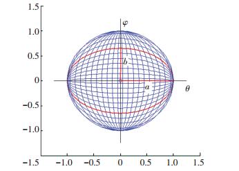
图 1和图 2中的两个椭圆相交于P(x, y),将点P坐标用参数θ、φ和1表示,如图 3和图 4所示,当x=0时,y=sin φ;当y=0时,x=sin θ.

|
图 3 点P在xoy上的参数坐标 Figure 3 The parameter coordinate of the point P on xoy |
|
图 4 点P(θ, φ, 1) 的参数关系 Figure 4 The parameter relationship of the point P(θ, φ, 1) |
单位球面上水平和垂直方向相较于点P的椭圆方程如图 5和图 6所示.在水平方向的椭圆中:a=1,b=sinφ;在垂直方向的椭圆中:a=sinθ,b=1.由式(4),过点P的椭圆方程为式(5) 和式(6).
|
图 5 xoy平面上的水平椭圆 Figure 5 The horizontal ellipse on the plane xoy |

|
图 6 xoy平面上的垂直椭圆 Figure 6 The vertical ellipse on the plane xoy |
| $ 由\frac{{{x^2}}}{1} + \frac{{{y^2}}}{{{{\sin }^2}\varphi }} = 1, $ |
有
| $ \left\{ \begin{array}{l} x = \sqrt {1 - \frac{{{y^2}}}{{{{\sin }^2}\varphi }}} \\ y = \sin \varphi \sqrt {1 - {x^2}} \end{array} \right. , $ | (5) |
| $ \left\{ \begin{array}{l} x = \sin \theta \sqrt {1 - {y^2}} \\ y = \sqrt {1 - \frac{{{x^2}}}{{{{\sin }^2}\theta }}} \end{array} \right. . $ | (6) |
上述每个椭圆在P(x, y)上具有相同的x,y变量,由式(3)、(5) 和(6) 计算如下.
1) 对于变量x,
| $ \sqrt {1 - \frac{{{y^2}}}{{{{\sin }^2}\varphi }}} = \sin \theta \sqrt {1 - {y^2}} , $ |
解得
| $ y = \frac{{\cos \theta \sin \varphi }}{{\sqrt {1 - {{\sin }^2}\theta {{\sin }^2}\varphi } }}. $ |
2) 对于变量y,
| $ \sin \varphi \sqrt {1 - {x^2}} = \sqrt {1 - \frac{{{x^2}}}{{{{\sin }^2}\theta }}} , $ |
解得
| $ x = \frac{{\sin \theta \cos \varphi }}{{\sqrt {1 - {{\sin }^2}\theta {{\sin }^2}\varphi } }}. $ |
3) 对于变量z,
| $ z = \pm \sqrt {1 - {x^2} - {y^2}} = \pm \frac{{\cos \theta \cos \varphi }}{{\sqrt {1 - {{\sin }^2}\theta {{\sin }^2}\varphi } }}, $ |
则,在单位球面上点P在笛卡尔坐标系下表示为
| $ P\left( {x,y,z} \right) = P\left( {\frac{{\sin \theta \cos \varphi }}{{\sqrt {1 - {{\sin }^2}\theta {{\sin }^2}\varphi } }},\frac{{\cos \theta \sin \varphi }}{{\sqrt {1 - {{\sin }^2}\theta {{\sin }^2}\varphi } }}, \pm \frac{{\cos \theta \cos \varphi }}{{\sqrt {1 - {{\sin }^2}\theta {{\sin }^2}\varphi } }}} \right). $ | (7) |
取单位球面底部的1/4球片作为参考面,因要研究其表面的弧线,故以下称该1/4球片为1/4网片S,在该1/4网片上建立位置矢量({θ,φ}∈[-π/4,π/4]),如图 7所示.推导并求得相应微分方程及夹角.

|
图 7 1/14网片图 Figure 7 1/4-sphere-patch |
| $ \hat {\boldsymbol{P}}\left( {x,y,z} \right) = \left\{ {\begin{array}{*{20}{c}} {\frac{{\sin \theta \cos \varphi }}{{\sqrt {1 - {{\sin }^2}\theta {{\sin }^2}\varphi } }}i}\\ {\frac{{\cos \theta \sin \varphi }}{{\sqrt {1 - {{\sin }^2}\theta {{\sin }^2}\varphi } }}j}\\ { \frac{{-\cos \theta \cos \varphi }}{{\sqrt {1 - {{\sin }^2}\theta {{\sin }^2}\varphi } }}k} \end{array}} \right\} . $ |
设矢量ĝ1和ĝ2是位置变量θ和φ的偏导数,法向量
| $ {{\hat {\boldsymbol{g}}}_1} = \frac{{\partial \hat P}}{{\partial \theta }} = \left\{ {\begin{array}{*{20}{c}} {\frac{{\cos \theta \cos \varphi }}{{\sqrt {(1 - {{\sin }^2}\theta {{\sin }^2}\varphi )^3} }}i}\\ { \frac{-{\sin \theta {{\sin }^2}\varphi \cos ^2 \varphi }}{{\sqrt {(1 - {{\sin }^2}\theta {{\sin }^2}\varphi )^3} }}j}\\ {\frac{{\sin \theta {{\cos }^3}\varphi }}{{\sqrt {(1 - {{\sin }^2}\theta {{\sin }^2}\varphi )^3} }}k} \end{array}} \right\} . $ | (8) |
| $ {{\hat {\boldsymbol{g}}}_2} = \frac{{\partial P}}{{\partial \varphi }} = \left\{ {\begin{array}{*{20}{c}} { \frac{-{\sin \theta {{\cos }^2}\theta \sin \varphi }}{{\sqrt {(1 - {{\sin }^2}\theta {{\sin }^2}\varphi )^3} }}i}\\ {\frac{{\cos \theta \cos \varphi }}{{\sqrt {(1 - {{\sin }^2}\theta {{\sin }^2}\varphi )^3} }}j}\\ {\frac{{{{\cos }^3}\theta \sin \varphi }}{{\sqrt {(1 - {{\sin }^2}\theta {{\sin }^2}\varphi )^3} }}k} \end{array}} \right\} . $ | (9) |
由式(8) 和(9),基向量ĝ1和ĝ2在球面位置的改变,其大小║ĝ1║和║ĝ2║也随之变化,在坐标原点(0, 0) 和沿着两轴方向(θ=0,φ=0) 二者相互垂直,大小为单位长度,同时,单位球面上法向量的大小║

|
图 8 向量在(0, 0) 和(-π/4,π/4) 的1/4网片 Figure 8 1/4 of Vector, in (0, 0) and (-π/4, π/4) mesh |
| $ \hat {\boldsymbol{N}} = {{\hat {\boldsymbol{g}}}_1} \times {{\hat {\boldsymbol{g}}}_2} = \left\{ {\begin{array}{*{20}{c}} {\frac{{ - \sin \theta {{\cos }}\theta {{\cos }^2}\varphi }}{{(1 - {{\sin }^2}\theta {{\sin }^2}\varphi )^2 }}i}\\ {\frac{{ - {{\cos }^2}\theta \sin \varphi \cos \varphi }}{{(1 - {{\sin }^2}\theta {{\sin }^2}\varphi )^2 }}j}\\ {\frac{{{{\cos }^2}\theta {{\cos }^2}\varphi }}{{(1 - {{\sin }^2}\theta {{\sin }^2}\varphi )^2 }}k} \end{array}} \right\} . $ | (10) |
| $ \hat {\boldsymbol{n}} = \frac{{{{\hat {\boldsymbol{g}}}_1} \times {{\hat {\boldsymbol{g}}}_2}}}{{\left\| {{{\hat {\boldsymbol{g}}}_1} \times {{\hat {\boldsymbol{g}}}_2}} \right\|}} = \frac{{\hat {\boldsymbol{N}}}}{{\left\| {\hat {\boldsymbol{N}}} \right\|}} = \left\{ {\begin{array}{*{20}{c}} {\frac{{ - \sin \theta \cos \varphi }}{{\sqrt {1 - {{\sin }^2}\theta {{\sin }^2}\varphi } }}i}\\ {\frac{{ - \cos \theta \sin \varphi }}{{\sqrt {1 - {{\sin }^2}\theta {{\sin }^2}\varphi } }}j}\\ {\frac{{\cos \theta \cos \varphi }}{{\sqrt {1 - {{\sin }^2}\theta {{\sin }^2}\varphi } }}k} \end{array}} \right\} . $ | (11) |
| $ \left. \begin{array}{l} \left\| {{{\hat {\boldsymbol{g}}}_1}} \right\| = \sqrt {g_{1x}^2 + g_{1y}^2 + g_{1z}^2} \\ \left\| {{{\hat {\boldsymbol{g}}}_2}} \right\| = \sqrt {g_{2x}^2 + g_{2y}^2 + g_{2z}^2} \\ \left\| {\hat {\boldsymbol{N}}} \right\| \equiv 1 \end{array} \right\} . $ | (12) |
两个基向量的雅可比矩阵的秩是2,并可确定该位置矢量(除两极以外,θ=φ=0是奇点),如式(13) 所示.
| $ \begin{array}{l} \boldsymbol{J} = \left( {\begin{array}{*{20}{c}} {\frac{{\partial {P_x}}}{{\partial \theta }}}&{\frac{{\partial {P_x}}}{{\partial \varphi }}}\\ {\frac{{\partial {P_y}}}{{\partial \theta }}}&{\frac{{\partial {P_y}}}{{\partial \varphi }}}\\ {\frac{{\partial {P_z}}}{{\partial \theta }}}&{\frac{{\partial {P_z}}}{{\partial \varphi }}} \end{array}} \right) = \frac{1}{{\sqrt {{{\left( {1 - {{\sin }^2}\theta {{\sin }^2}\varphi } \right)}^3}} }} \cdot \\ \left( {\begin{array}{*{20}{c}} {\cos \theta \cos \varphi }&{ - \sin \theta {{\cos }^2}\theta \sin \varphi }\\ { - \sin \theta \sin \varphi {{\cos }^2}\varphi }&{\cos \theta \cos \varphi }\\ {\sin \theta \cos ^3\varphi }&{\cos \theta {{\sin }^3}\varphi } \end{array}} \right) \end{array} . $ | (13) |
依据经典质点力学理论,可导出度量张量的高斯第一基本型,基向量(ĝ1, ĝ2,
| $ {{\boldsymbol{g}}_{mn}} = \left| {\begin{array}{*{20}{c}} {{\hat {\boldsymbol{g}}_1} \cdot {\hat {\boldsymbol{g}}_1}{\hat {\boldsymbol{g}}_1} \cdot {\hat {\boldsymbol{g}}_2}}&{{\hat {\boldsymbol{g}}_1} \cdot \hat {\boldsymbol{N}}}\\ {{\hat {\boldsymbol{g}}_2} \cdot {\hat {\boldsymbol{g}}_1}{\hat {\boldsymbol{g}}_2} \cdot {\hat {\boldsymbol{g}}_2}}&{{\hat {\boldsymbol{g}}_2} \cdot \hat {\boldsymbol{N}}}\\ {{\hat {\boldsymbol{g}}_3} \cdot \hat {\boldsymbol{N}}{\hat {\boldsymbol{g}}_3} \cdot \hat {\boldsymbol{N}}}&{\frac{{{\hat {\boldsymbol{g}}_1} \times {\hat {\boldsymbol{g}}_2}}}{{\left| {{\hat {\boldsymbol{g}}_1} \times {\hat {\boldsymbol{g}}_2}} \right|}} \cdot \frac{{{\hat {\boldsymbol{g}}_1} \times {\hat {\boldsymbol{g}}_2}}}{{\left| {{\hat {\boldsymbol{g}}_1} \times {\hat {\boldsymbol{g}}_2}} \right|}}} \end{array}} \right| = \left| {\begin{array}{*{20}{c}} {{g_{11}}}&{{g_{12}}}&0\\ {{g_{21}}}&{{g_{22}}}&0\\ 0&0&{{g_{33}}} \end{array}} \right| \\= \left| {\begin{array}{*{20}{c}} {\frac{{{{\cos }^2}\varphi }}{{{{\left( {1 - {{\sin }^2}\theta {{\sin }^2}\varphi } \right)}^2}}}}&{\frac{{ - \sin\theta \cos\theta \sin\varphi \cos \varphi }}{{{{\left( {1 - {{\sin }^2}\theta {{\sin }^2}\varphi } \right)}^2}}}}&0\\ {\frac{{ - \sin\theta \cos\theta \sin\varphi \cos \varphi }}{{{{\left( {1 - {{\sin }^2}\theta {{\sin }^2}\varphi } \right)}^2}}}}&{\frac{{{{\cos }^2}\theta }}{{{{\left( {1 - {{\sin }^2}\theta {{\sin }^2}\varphi } \right)}^2}}}}&0\\ 0&0&1 \end{array}} \right|. $ | (14) |
可得
| $ g = {g_{11}}{g_{22}} - {\left( {{g_{12}}} \right)^2} = \frac{{{{\cos }^2}\theta \cos \varphi }}{{{{\left( {1 - {{\sin }^2}\theta {{\sin }^2}\varphi } \right)}^3}}} . $ | (15) |
第一基本型的微分形式,弧微分的平方为
| $ {\left( {{\rm{d}}s} \right)^2} = {g_{11}}{\left( {{\rm{d}}\theta } \right)^2} + 2{g_{12}}\left( {{\rm{d}}\theta {\rm{d}}\varphi } \right) + {g_{22}}{\left( {{\rm{d}}\varphi } \right)^2} . $ | (16) |
再由式(15) 和式(16),整理得到式(17),可算出成型路径上的弧长和角度为
| $ {\left( {{\rm{d}}s} \right)^2} = \frac{{{{\cos }^2}\varphi }}{{{{\left( {1 - {{\sin }^2}\theta {{\sin }^2}\varphi } \right)}^2}}}{\left( {{\rm{d}}\theta } \right)^2} - \frac{{2\sin \theta \cos \theta \sin \varphi \cos \varphi }}{{{{\left( {1 - {{\sin }^2}\theta {{\sin }^2}\varphi } \right)}^2}}}\left( {{\rm{d}}\theta {\rm{d}}\varphi } \right) + \frac{{{{\cos }^2}\theta }}{{{{\left( {1 - {{\sin }^2}\theta {{\sin }^2}\varphi } \right)}^2}}}{\left( {{\rm{d}}\varphi } \right)^2} . $ | (17) |
1) 计算弧长s
| $ {{\rm{d}}s = \sqrt {\frac{{{{\cos }^2}\theta }}{{{{\left( {1 - {{\sin }^2}\theta {{\sin }^2}\varphi } \right)}^2}}}{{\left( {{\rm{d}}\theta } \right)}^2} - \frac{{2\sin \theta \cos \theta \sin \varphi \cos \varphi }}{{{{\left( {1 - {{\sin }^2}\theta {{\sin }^2}\varphi } \right)}^2}}}\left( {{\rm{d}}\theta {\rm{d}}\varphi } \right) + \frac{{{{\cos }^2}\theta }}{{{{\left( {1 - {{\sin }^2}\theta {{\sin }^2}\varphi } \right)}^2}}}{{\left( {{\rm{d}}\varphi } \right)}^2}} } . $ | (18) |
式(18) 的右边含有θ和φ的合成方向,不便计算.但可以采取固定一个变量,沿着另一变量的方向计算.如沿着θ方向移动,保持φ不变,即dφ=0.
| $ \begin{array}{l} {\left( {{\rm{d}}s} \right)^2} = {g_{11}}{\left( {{\rm{d}}\theta } \right)^2}\\ s = \int {\sqrt {{g_{11}}} } \left( {{\rm{d}}\theta } \right) = \int {\frac{{\cos \varphi }}{{\left( {1 - {{\sin }^2}\theta {{\sin }^2}\varphi } \right)}}{\rm{d}}\theta .} \end{array} $ | (19) |
2) 计算角度ω
计算两弧相交的弧角ω,见式(20).
| $ \omega = a\cos \left( {\frac{{{g_{12}}}}{{\sqrt {{g_{11}}{g_{22}}} }}} \right) = a\cos \left( { - \sin \theta \sin \varphi } \right). $ | (20) |
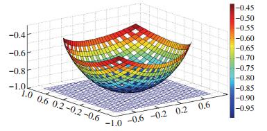
为考察复合材料网壳结构模型的成型效果[12],达到数学建模的可视化,对该建模方法分别按纤维材料带经纬正交5×5、10×10、20×20和30×30编织进行了仿真实验[13],以考察模型的成型形态、网孔大小及网孔分布情况[14-15],各仿真图右侧的彩色条形图例是表示从底部到边缘的各测地线曲率分布情况.
3.1 MATLAB仿真实验在该模型中,取纤维复合材料带长度R=300 mm,宽度5 mm,角度为{θ,φ}∈[-π/2,π/2].分别采用5×5、10×10、20×20和30×30编织的算例,其网壳构型三维仿真分别如图 9~12所示,图中xoy平面的蓝色网格带是成型前正交编织的纤维复合材料带,数学模型导入后得出网壳结构的构件成型形状,其经纬方向的复合材料带的叠接交织的曲率由构件底部至向上开口方向渐进变小,同纬度上(等高线)交织点的曲率是相同的,其交角随着维度的升高渐次变小.同时可见,在等长度材料带的情况下,随着经纬编织密度的增大,构件所生成的网孔面积逐渐变小,结构成型的测地表面线间耦合越紧密,耗用的材料也越多.

|
图 9 5×5网壳结构的三维仿真图 Figure 9 5×5 Meshed shell structures of 3D simulation |
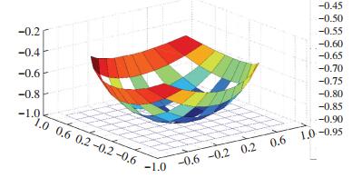
|
图 10 10×10网壳结构的三维仿真图 Figure 10 10×10 Meshed shell structures of 3D simulation |
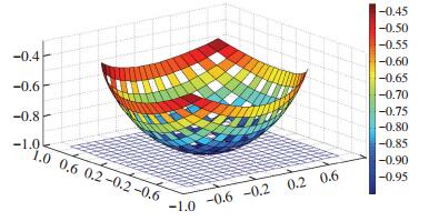
|
图 11 20×20网壳结构的三维仿真图 Figure 11 20×20 Meshed shell structures of 3D simulation |
|
图 12 30×30网壳结构的三维仿真图 Figure 12 30×30 Meshed shell structures of 3D simulation |
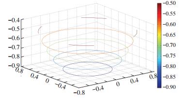
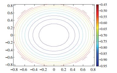
网壳三维等高线和二维等高线分别如图 13和图 14所示,直观体现了镂空网壳等纬度线上的弧长和交角均分别相同,材料带的锐角交角沿经度线方向由下至上(z轴正方向)逐渐变小.
|
图 13 网壳三维等高线图 Figure 13 Meshed shells 3D contour map |
|
图 14 网壳二维等高线图 Figure 14 Meshed shells 2D contour map |
仿真实验验证了基于单位球面的测地线网壳结构的建模方法可实现网壳类外形构件的建模、仿真和成型.
3.2 网壳结构的生产验证尽管仿真实验验证了数学模型构型的可实现性,但能否适合生产制造还需进行生产相关的验证,通过MATLAB导出程序输入铺放机器人的程控单元.
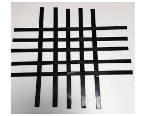
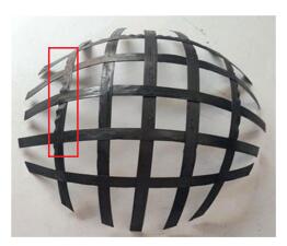
3.2.1 工艺采用江苏恒神公司研发的T300级碳纤维/环氧单向预浸复合材料带,宽度5 mm,厚度1 mm,正交编织铺置于胎膜内,加压固化温度170 ℃,固化时间150 min.编织截图如图 15所示,成型后如图 16所示,与仿真网壳构型结构相符.
|
图 15 复合材料带隔行正交编织预铺 Figure 15 Composite materials with interlaced orthogonal woven before paving |
|
图 16 复合材料网壳结构成型图 Figure 16 Composite meshed shell structures molding figure |
升温固化过程中加温箱中有轻微炸裂的异响,分析是环氧预浸材料带交叉节点处因高温高压膨胀而轻微微开裂所发出的响声.
3.2.3 存在问题及原因网壳构型虽与预期相符,但试件边缘内外侧出现最大约0.05 mm的褶皱现象,如图 16的矩形框所示,原因是该生产工艺中支撑模具的内膜压实度不均造成,在未来批量化生产时将改进工艺予以解决;对于试件边缘平齐性不一致的问题可通过边缘修剪和模型改进得到改善.
3.2.4 试件结构特点一体化一次成型;用材达到最少、结构超轻、叠接处因环氧的特性而自动粘结,纤维无断丝和破坏,试件整体耦合与稳固性好;网孔的镂空部分可根据需要设置其他功能材料或器件而制造其他功能构件.
4 结论本文的建模方法,突破了传统手工成型的低效和高耗能的设计和工艺,能够便捷、高效实现曲面网壳的减重设计和制造,利于结构-功能-设计制造的轻量化和一体化.
1) 复合材料构件的结构可通过空间曲面映射的数学建模进一步挖掘其结构性能,提升复合材料构件的超轻化.
2) 仿真实验表明,采用基于测地线原理的建模方法,可直接实现变曲率复合材料网壳的结构成型,并可考察其结构各相位等高线的耦合关系,较其他建模方法更便捷、直观.
3) 经试制和测量,该模型的算法可行且网壳构型同一取样点的测量值与仿真值精度误差小于0.01 mm,在未来的研究中应进一步优化模型算法,并探索利用传感器技术研究网壳的力学性能、优化成形工艺、振动和破坏等特性,以更有利于自动化制造.
| [1] |
赖长亮, 刘闯, 王俊彪. IsoTruss超轻复合材料结构制造及力学性能测试[J]. 复合材料学报, 2014, 31(2): 127–134.
LAI Changliang, LIU Guang, WANG Junbiao. Fabrication and mechanical property test of IsoTruss ultra-lightweight composite structures[J]. Acta Materiae Composite Sinica, 2014, 31(2): 127–134. |
| [2] |
韩小进, 孙慧玉, 闫光, 等. 三维五向编织复合材料渐进损伤分析的数值方法[J]. 复合材料学报, 2012, 29(6): 219–224.
HAN Xiaojin, SUN Huiyu, YAN Guang, et al. Numerical method for progressive damage analysis of 3D five-directional braided composite[J]. Acta Materiae Composite Sinica, 2012, 29(6): 219–224. |
| [3] |
卢子兴, 王晓英, 俸翔. 复合材料层合板临界屈曲载荷分散性[J]. 复合材料学报, 2013, 30(1): 194–200.
LU Zixing, WANG Xiaoying, FENG Xiang. Critical buckling load discrepancy of composite laminates[J]. Acta Materiae Composite Sinica, 2013, 30(1): 194–200. |
| [4] | ROBERT J Lind. Variably-curved, meshed thin shells: geometry, mechanics, and fabrication[D]. American: Tufts University, 2008. |
| [5] |
秦升学, 郭笑笑, 蒋少松, 等. 连续玻纤/PE增强复合带弹性参数计算方法[J]. 材料科学与工艺, 2016, 24(3): 40–44.
QIN Shengxue, GUO Xiaoxiao, JIANG Shaosong, et al. The method for calculating the elastic parameters of continuous glass fiber/PE reinforced composite[J]. Materials Science and Technology, 2016, 24(3): 40–44. DOI: 10.11951/j.issn.1005-0299.20160307 |
| [6] |
古托夫斯基TG. 先进复合材料制造技术[M]. 北京: 化学工业出版社, 2004: 236-286.
GUTOWSKIT G. Advanced composites manufacturing technology[M]. Beijing: Chemical Industry Press, 2004: 236-286. |
| [] | MA Liangkai, SRIVASTAVA Rakesh, BARPANDA Dev, et al.Journal of reinforced plastics and composites[J]. December 2013, 32(24): 1916-1927. |
| [8] | AHMAD Rezaghasemi, MOHAMMAD Hadi Hajmohammad. Multi-objective optimization of laminated composite shells for minimum mass/cost and maximum buckling pressure with failure criteria under external hydrostatic pressure[J]. Structural and Multidisciplinary Optimization, 2017, 55(3): 1051–1062. DOI: 10.1007/s00158-016-1559-2 |
| [9] | YIN Jin, YANG Dongsheng, ZHANG Sheng. Laminated composite plate and shell elementsbased on combination method[J]. Acta Aeronautica et Astronautica Sinica, 2013, 34(1): 89–96. |
| [10] | LIUA Bo, FERREIRAB A J M, XINGA Y F, et al. Analysis of functionally graded sandwich and laminated shells using a layerwise theory and a differential quadrature finite element method[J]. Composite Structures, 2016, 136(2): 546–553. |
| [11] | SUDIP Dey, AMIT Karmakar. Dynamic analysis of delaminated composite conical shells under low velocity impact[J]. Journal of Reinforced Plastics and Composites, 2013, 32(6): 380–392. DOI: 10.1177/0731684412465663 |
| [12] | PANNEERDHASS R, GNANAVELBABU A, RAJKUMAR K. Preparation, properties and machinability study of luffa fiber-groundnut shell reinforced epoxy composite[J]. Applied Mechanics and Materials, 2016, 852: 29–35. DOI: 10.4028/www.scientific.net/AMM.852 |
| [13] | CUI X, LIU G L, LU C, et al. Study on CF reinforced interface properties of PES-C resin matrix composite[J]. Advanced Materials Research, 2014, 887-888: 70–76. DOI: 10.4028/www.scientific.net/AMR.887-888 |
| [14] |
罗忠, 朱云鹏, 陈晓兵, 等. 复合材料层合板相似模型的几何区间确定方法[J]. 机械工程学报, 2014, 50(9): 58–64.
LUO Zhong, ZHU Yunpeng, CHEN Xiaobing, et al. Study of the structure size interval of similar test model of the laminated composite plate[J]. Journal of Mechanical Engineering, 2014, 50(9): 58–64. |
| [15] | GUO Li, CAI Xiaolan, ZHOU Lei, et al. Optimization of process parameters for in high-energy ball milling of CNTs/Al2024 composites through response surface methodology[J]. Journal of Harbin Institute of Technology, 2016, 23(1): 53–59. |
 2017, Vol. 25


