2. 材料电磁过程研究教育部重点实验室(东北大学), 沈阳 110004;
3. 东北大学 材料科学与工程学院,沈阳 110004
2. Key Laboratory of Electromagnetic Processing of Materials, Ministry of Education (Northeastern University), Shenyang 110004, China;
3. School of Materials Science and Engineering, Northeastern University, Shenyang 110004, China
3D打印技术(3D printing)是20世纪90年代出现的一种新型快速成型技术.该技术利用高能激光热源将金属粉末完全熔化,经快速冷却凝固成型,从而得到高致密度、高精度的金属零部件.3D打印技术在制备复杂形状零部件方面具有明显优势,已被广泛应用于制备各种复杂结构零部件[1-9].作为典型的轻质高强材料,铝合金的3D打印制备工艺备受关注,但受自身激光吸收率低、导热率高、凝固收缩大等特点的限制,3D打印用铝合金体系发展缓慢.近年来,国内外学者针对铝合金3D打印工艺展开了大量研究[10-16],目前,AlSi10Mg合金被公认为比较适合于3D打印技术.扫描方式、基板预热、微量成分,以及粉材的形状、粒径等多方面因素均会对3D打印AlSi10Mg制品的性能产生影响.Kempen[13]等人使用AlSi10Mg合金进行3D打印获得致密度达到99.5%,抗拉强度达到400 MPa的零部件.尽管国内学者已对AlSi10Mg合金粉材及3D打印技术做了大量的研究工作[17-18],但粉材质量、扫描参数,扫描方法等关键参数的掌控仍不如国外相关企业,3D打印效率和产品质量仍有待提高.
结合3D打印技术的发展现状,本文通过对德国EOSM28金属粉末激光烧结系统所制备样品的组织性能分析,解析进口设备的扫描方式,并结合扫描方式及3D打印技术金属凝固的特点,分析3D打印制品力学性能优异的原因.
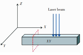
1 实验利用EOSM280金属粉末激光烧结系统,按设备自动设定的工艺参数进行AlSi10Mg材料的3D打印,AlSi10Mg的名义成分(质量分数/%)为:Si 9.0~11.0,Mg 0.4~0.6,Fe≤2.0,Cu≤0.6,Mn≤0.35,其他微量元素<0.25,余量为Al.将AlSi10Mg粉材沿不同构件方向制成8个尺寸为12 mm×12 mm×120 mm的3D打印试样,其中4个样品的长轴垂直于构建方向,另4个样品的长轴平行于构建方向,图 1所示为长轴垂直于构建方向试样.

|
图 1 试样构件方向示意图 Fig.1 Schematic of the construction method of the sample |
将3D打印试样分别沿垂直于构建方向和平行于构建方向切开,磨光、并进行电解抛光,用德国徕卡(Lecia)公司的DMI5000M光学金相显微镜观察其微观组织.用体积分数15%的盐酸对试样进行深腐蚀,用德国蔡司(Zeiss)公司生产的ULTRA PLUS场发射扫描电镜对三维形貌进行观察.将3D打印试样按GB228《金属材料室温试验方法》制备拉伸样品,用CMT-5105型微机控制电子万能拉伸实验机进行常温拉伸实验,设定拉伸速率为1 mm/min,每个条件取3个试样进行拉伸,所得结果取算术平均值, 利用场发射扫描电镜对断口形貌进行观察.
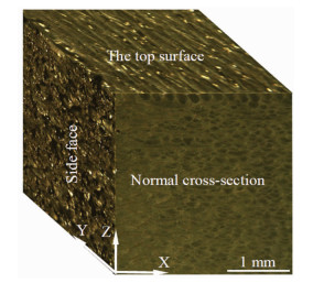
2 结果与分析用体视显微镜(奥林巴斯的SZX16)对试样的侧面、顶面及磨光腐蚀后的正面进行拍照,并拼接成三维宏观组织形貌,如图 2所示,其中Z方向为构建方向,垂直于Z方向的顶面为构建面(或扫描面).由图 2可以看到:3D打印试样的顶面和侧面的形貌明显不同,顶面由一道道平行的条纹构成,各条纹与焊缝上表面形貌相似;侧面则比较粗糙,有大量的孔洞沟壑和未熔的金属粉末;正面界面的典型组织呈“鱼鳞状”,实为激光扫描熔池凝固后形成的,在样品横截面顶部可以看到最后一层扫描所形成的较为完整的“U”形组织.

|
图 2 3D打印试样的三维宏观组织 Fig.2 Optical micrographs from three orthogonal planes showing the macrostructures of the sample |
3D打印试样顶层(距顶层约100 μm)磨光后的金相显微组织如图 3所示,可以看到试样顶层附近(俯视图)的典型组织呈平行的“带状”,结合3D打印技术特点可知,这些“带状”组织为激光平行扫描形成熔池凝固后的俯视组织,由这些“带状”组织的间距可知,激光扫描时两束激光的间距约为210 μm.在图 2的局部区域还可以看到下层的“带状”组织,这些组织与上层组织呈一定角度(约为120°),由此可知,激光扫描过程中相邻两层间扫描方向的夹角约为120°.

|
图 3 试样顶层附近的微观组织 Fig.3 The microstructure near the top surface of the 3D printing sample |
图 4(a)为3D打印试样横截面磨光后的金相显微组织,可以看到,在3D打印样品顶面皮下层可以清楚地看到较为完整“U”形组织,这些“U”形组织边界清晰,在水平方向相互叠加,经测量熔池上部的宽度约为290 μm,测量熔池的高度约为180 μm,两熔池底部间距约为210 μm,激光扫描形成的凝固熔池一层层叠加形成了鱼鳞状组织.凝固的“U”形组织内部为典型的柱状晶,晶粒的生长方向垂直于熔池底部.顶面典型组织(俯视图)的局部放大图如图 4(b)所示, 可以看到平行的带状组织之间的间距约为210 μm(与熔池底部间距相同),带状组织内的晶粒呈等轴状(实为柱状晶的横截面),这些晶粒在带状组织内分布不均匀,边部较细小,心部粗大.熔池凝固过程中边部和心部冷却速率的差异是导致这种柱状晶分布不均匀的主要原因.

|
图 4 3D打印试样不同方向的微观组织 Fig.4 The microstructure in different direction of the 3D printing sample :(a) the front surface; (b) the top surface |
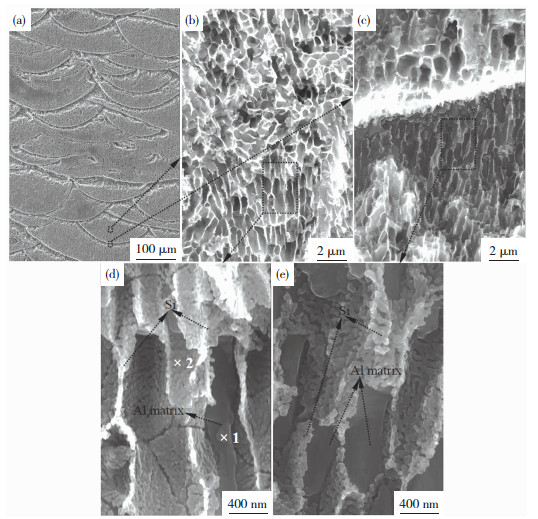
3D打印样品横截面经深腐蚀后典型微观组织照片如图 5所示.

|
图 5 3D打印试样深腐蚀后的形貌:(a)正面低倍形貌;(b)、(c)对应图 5(a)中框图位置的局部放大图;(d)对应图 5(b)中框图位置的局部放大图;(e)对应图 5(c)中框图位置的局部放大图 Fig.5 Morphology of the 3D printing sample after deep corrosion:(a) low magnification of the front surface; (b) the local magnification of the corresponding position of Fig. 5(a); (c) the local magnification of the corresponding position of Fig. 5(a); (d) the local magnification of the corresponding position of Fig. 5(b); (e) the local magnification of the corresponding position of Fig. 5(c) |
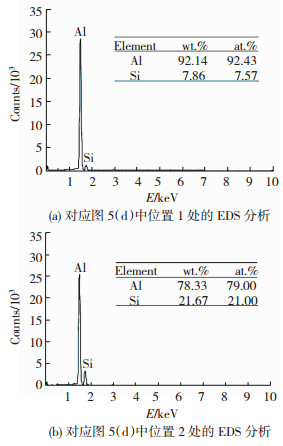
由图 5可以看出,深腐蚀后试样的典型组织形貌呈鱼鳞状,凝固熔池底部附近的耐蚀程度较差,形成较深的腐蚀坑.对凝固熔池中心部位的典型位置处进行高倍观察(图 5(b)和(d)),可以看到在熔池内部中心区域的典型组织呈“管状”,管状组织的间距约为0.5 μm,这些“管状”结构的内壁并不光滑,多呈颗粒状,能谱分析结果(图 6(a))表明,这些颗粒状组织Si含量较高,结合AlSi10Mg合金的特点可知, 这些颗粒状相为共晶Si颗粒,图 5(d)显示这些Si颗粒尺寸非常细小.在管状组织之间可以看到表面比较平滑的组织(图 5(d)中点2处),经能谱分析可知该处的Al含量较高(图 6(b)),这些为Al基体.

|
图 6 针对图 5(d)部分区域的能谱分析结果 Fig.6 EDS spectrum analysis corresponding to the points of Fig. 5 (d):(a) EDS spectrum analysis corresponding to the 1 point; (b)EDS spectrum analysis corresponding to the 2 point |
对熔池底部附近的组织进行观察(图 5(c)和(e)),可以看到在熔池底部附近存在明显的组织突变区,熔池底部的枝晶间距非常细小,Si颗粒亦非常细小,如图 5(c)所示,而在熔池底部附近的热影响区,枝晶间距比较粗大,Si颗粒的尺寸也比较粗大,如图 5(e)所示.如前所述,激光扫描构建过程所形成的熔池非常小(宽度为210 μm、深度仅为180 μm),熔池凝固过程中可以获得很高的冷却速率,这有利于获得细小的共晶组织和细小的共晶Si颗粒,而熔池底部的冷却速率更快,形成的共晶组织和Si颗粒更细小.
试样沿X向和沿Z向的拉伸力学性能如表 1所示,可以看到3D打印试样X向和Z向的屈服强度分别为292.5和240.0 MPa,抗拉强度分别为487.5和490.0 MPa,延伸率分别为9.0%和7.0%,弹性模量分别为69.7和68.3 MPa, 样品在两个方向的力学性能差别不大,且强度及延伸率明显优于相关资料中[19]该合金的强度和延伸率.
| 表 1 3D打印试样不同方向的力学性能 Table 1 The mechanical properties of the 3D printing samples along different direction |
长轴平行于构建方向(Z向)和垂直于构建方向(X向)的两组拉伸试样的典型断口分别如图 7(a)、(b)所示,可以看出两个方向拉伸试样的断口形貌明显不同.沿Z向的拉伸断口表面出现很多“沟壑”,这些“沟壑”的宽度在100 μm左右,有些长度可达1 000 μm,在这些沟壑之间还存在一些不规则的孔洞,局部放大结果表明(图 7(c)),这些孔洞内表面非常光滑,应为凝固过程中熔池底部补缩不足形成的孔洞.这表明沿Z向拉伸时,试样主要沿熔池底部断裂,熔池凝固过程中熔池底部为组织突变区,这个区域的组织突变和形成的孔洞可能是导致其开裂的主要原因.沿X向的拉伸断口表明凹凸不平,没有沿一定方向分布的“沟壑”,在凹凸不平的表面上同样存在大量孔洞,局部放大结果(图 7(d))表明,这些孔洞处的断口表面也比较光滑.

|
图 7 3D打印样品不同方向拉伸断口的典型形貌:(a) Z向拉伸试样断口;(b) X向拉伸试样断口;(c) 图 7(a)对应位置的局部放大图;(d) 图 7(b)对应位置的局部放大图 Fig.7 Typical fracture morphology of the samples along different direction: (a) the tensile fracture of Z direction; (b) the tensile fracture of X direction; (c) the local magnification of the corresponding position of Fig. 7(a); (d) the local magnification of the corresponding position of Fig. 7(b) |
1) 3D打印过程中激光束扫描形成熔池的深度约为180 μm,熔池宽度约为290 μm,同层扫描过程中激光束的间距约为210 μm,层与层间的扫描方向互成120°.
2) 熔池凝固后形成典型的“U”形组织,“U”形组织内形成典型的柱状晶,其生长方向与传热方向平行,晶粒内的共晶组织呈“管状”,枝晶臂上的Si颗粒细小均匀.
3) 3D打印样品平行于构建方向的抗拉强度和延伸率分别为487.5 MPa和9.0%,垂直于构建方向的抗拉强度和延伸率分别为490.0 MPa和7.0%.
| [1] |
AMATO K N, GAYTAN S M, MURR L E, et al. Microstructures and mechanical behavior of Inconel 718 fabricated by selective laser melting[J]. Acta Materialia, 2012, 60(5): 2229-2239. DOI:10.1016/j.actamat.2011.12.032 |
| [2] |
KRUTH J P, FROYEN L, VAN VAERENBERGH J, et al. Selective laser melting of iron-based powder[J]. Journal of Materials Processing Technology, 2004, 149(1): 616-622. DOI:10.1016/j.jmatprotec.2003.11.051 |
| [3] |
THIJS L, VERHAEGHE F, CRAEGHS T, et al. A study of the microstructural evolution during selective laser melting of Ti-6Al-4V[J]. Acta Materialia, 2010, 58(9): 3303-3312. DOI:10.1016/j.actamat.2010.02.004 |
| [4] |
ROMBOUTS M, KRUTH J P, FROYEN L, et al. Fundamentals of selective laser melting of alloyed steel powders[J]. CIRP Annals-Manufacturing Technology, 2006, 55(1): 187-192. DOI:10.1016/S0007-8506(07)60395-3 |
| [5] |
ABE F, OSAKADA K, SHIOMI M, et al. The manufacturing of hard tools from metallic powders by selective laser melting[J]. Journal of materials processing technology, 2001, 111(1): 210-213. DOI:10.1016/S0924-0136(01)00522-2 |
| [6] |
VANDENBROUCKE B, KRUTH J P. Selective laser melting of biocompatible metals for rapid manufacturing of medical parts[J]. Rapid Prototyping Journal, 2007, 13(4): 196-203. DOI:10.1108/13552540710776142 |
| [7] |
LOUVIS E, FOX P, SUTCLIFFE C J. Selective laser melting of aluminium components[J]. Journal of Materials Processing Technology, 2011, 211(2): 275-284. DOI:10.1016/j.jmatprotec.2010.09.019 |
| [8] |
DADBAKHSH S, HAO L. Effect of Al alloys on selective laser melting behaviour and microstructure of in situ formed particle reinforced composites[J]. Journal of Alloys and Compounds, 2012, 541: 328-334. DOI:10.1016/j.jallcom.2012.06.097 |
| [9] |
GU D, WANg Z, SHEN Y, et al. In-situ TiC particle reinforced Ti-Al matrix composites: powder preparation by mechanical alloying and selective laser melting behavior[J]. Applied Surface Science, 2009, 255(22): 9230-9240. DOI:10.1016/j.apsusc.2009.07.008 |
| [10] |
BRANDL E, HECKENBERGER U, HOLZINGER V, et al. Additive manufactured AlSi10Mg samples using Selective Laser Melting (SLM): Microstructure, high cycle fatigue, and fracture behavior[J]. Materials & Design, 2012, 34: 159-169. DOI:10.1016/j.matdes.2011.07.067 |
| [11] |
READ N, WANG W, ESSA K, et al. Selective laser melting of AlSi10Mg alloy: Process optimisation and mechanical properties development[J]. Materials & Design, 2015, 65: 417-424. DOI:10.1016/j.matdes.2014.09.044 |
| [12] |
THIJS L, KEMPEN K, KRUTH J P, et al. Fine-structured aluminium products with controllable texture by selective laser melting of pre-alloyed AlSi10Mg powder[J]. Acta Materialia, 2013, 61(5): 1809-1819. DOI:10.1016/j.actamat.2012.11.052 |
| [13] |
KEMPEN K, THIJS L, VAN HUMBEECK J, et al. Mechanical properties of AlSi10Mg produced by selective laser melting[J]. Physics Procedia, 2012, 39: 439-446. DOI:10.1016/j.phpro.2012.10.059 |
| [14] |
LI Y, GU D. Parametric analysis of thermal behavior during selective laser melting additive manufacturing of aluminum alloy powder[J]. Materials & Design, 2014, 63: 856-867. DOI:10.1016/j.matdes.2014.07.006 |
| [15] |
BUCHBINDER D, SCHLEIFENBAUM H, HEIDRICH S, et al. High power selective laser melting (HP SLM) of aluminum parts[J]. Physics Procedia, 2011, 12: 271-278. DOI:10.1016/j.phpro.2011.03.035 |
| [16] |
MARTIN J H, YAHATA B D, HUNDLEY J M, et al. 3D printing of high-strength aluminium alloys[J]. Nature, 2017, 549(7672): 365-369. DOI:10.1038/nature23894 |
| [17] |
孙靖, 朱小刚, 王联凤, 等. 扫描方式与预热温度对激光选区熔化制备大尺寸AlSi10Mg合金性能的影响[J]. 机械工程材料, 2017, 41(10): 52-57. SUN Jing, ZHU Xiaogang, WANG Lianfeng, et al. Effect of scanning strategy and preheating temperature on properties of large-scale AlSi10Mg alloy prepared by selective laser melting[J]. Materials for Mechanical Engineering, 2017, 41(10): 52-57. DOI:10.11973/jxgccl201710012 |
| [18] |
张文奇, 朱海红, 胡志恒, 等. AlSi10Mg的激光选区熔化成形研究[J]. 金属学报, 2017(8): 918-926. ZHANG Wenqi, ZHU Haihong, HU Zhiheng, et al. Study on the selective laser melting of AlSi10Mg[J]. Acta Metallurgica Sinica, 2017(8): 918-926. DOI:10.11900/0412.1961.2016.00472 |
| [19] |
BOYER H E, GAIL T L. Materials Handbook Desk[M]. Edition: American Society for Metals, 1985.
|
 2019, Vol. 27


